Page 6 001970MAN-03 12-Feb-2019
General Overview
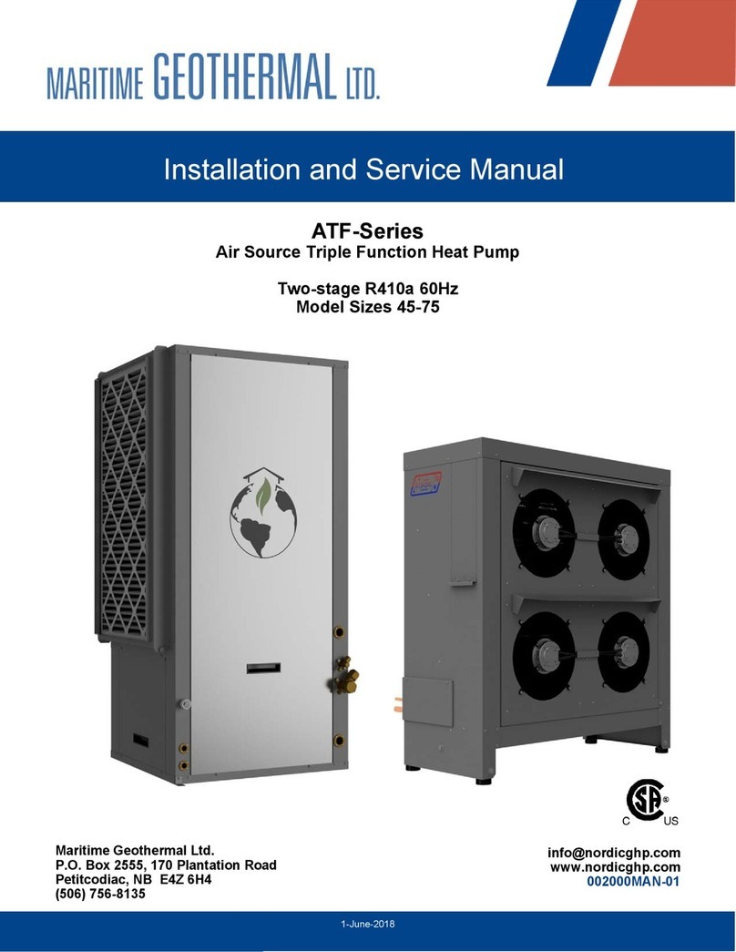
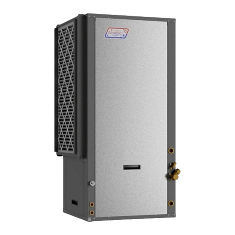
The ATW-Series heat pump is an air source heat pump
that can heat water for a hydronic heating system, or heat and
cool water for a hydronic heating/cooling system. Applications
include in-floor heating, heating through low-temperature radia-
tors, pre-heating domestic hot water through the use of an indi-
rect tank with hydronic coil, and heating and cooling through
hydronic air handlers.
Being an air source heat pump, it does not require a
ground loop, instead using an outdoor evaporator / condenser to
exchange heat with the outdoor air. Unlike most air source out-
door units on the market, this outdoor unit contains only an air
coil, ECM hub motor fan, heating mode electronic expansion
valve (EEV), and an outdoor temperature sensor.
The remaining components, including the compressor and
all electronics, are contained in the indoor unit. This has several
advantages: minimal installation and service work must be per-
formed outdoors, important components are in the conditioned
space for longevity, and heating domestic hot water is possible
(through a desuperheater circuit) since the fresh water lines are
inside and will never freeze.
The heat pump will be set up to heat or cool water in a
closed loop buffer tank to a user-selectable setpoint tempera-
ture; when a zone thermostat requires heat or cooling, it will
receive water flow by opening a zone valve or starting a zone
pump. Two tanks, heated and chilled, maybe used instead
where heating and cooling demands may occur simultaneously
or close together. Water temperature control will usually be
performed by a built-in routine that maintains the buffer tank
temperature without external sensors (’Setpoint Control’). Op-
tionally, BACnet, external tank sensors, or an external aquastat
can be used.
In additional to the main hydronic water heating/cooling
functions, there is a double-wall desuperheater for pre-heating
domestic hot water with ~5% of the heat pump’s capacity. This
function is only active when the heat pump is running for space
heating or cooling purposes. An energy-efficient bronze head
ECM circ pump for the desuperheater circuit is built in, along
with a temperature control to turn the pump off when the DHW
temperature reaches 140°F/60°C.
Two-stage scroll compressors are standard. The outdoor
air coil is e-coated for corrosion protection, and the coaxial hy-
dronic heat exchanger is copper / steel with optional CuNi inner
tube available for applications where water quality may be an
issue. The cabinets are powder coated galvanized sheet metal.
Control is overseen by the Nordic GEN2 programmable control
board, which has many advanced features like laptop connectiv-
ity via the free PC App software, data logging & graphing, and
real time readout from electronic temperature & pressure sen-
sors.
1. Heating Mode
In hydronic heating mode, the heat pump heats water in
the buffer tank. Superheat is controlled by the heating EEV
located in the outdoor unit while the EEV in the indoor unit is set
to full open. As the unit operates, heat is extracted from the
outdoor air, which causes the air coil to eventually frost up to the
point that a defrost cycle is required. The time between defrost
cycles varies depending on the outdoor conditions; refer to the
Defrost Operation section below.
If the outdoor temperature is above 34°F(1°C), the outdoor
unit fan starts and stops when the heat pump starts and stops.
If the temperature is below 34°F(1°C), the outdoor fan will re-
main on at a very slow speed when the heat pump is off in order
ATW System Description
minimize the chance of a fan freeze up, and to prevent snow
from entering the unit through the fan opening during a snow
storm. The outdoor fan is controlled based on the suction pres-
sure and will slowly ramp up to the required speed when the
system starts. The heat pump will turn off and only the auxiliary
heating system will operate if the outdoor temperature gets too
cold. Refer to the Model Specific Information section for the
limits of operation.
Any air source heat pump will need auxiliary heat; see
Sizing section. This may almost any heating device, but
the most convenient is electric elements in the buffer tank, con-
trolled by the heat pump’s stage 3 temperature control (stages 1
& 2 being the two compressor stages).
Defrost Operation
The heat pump has an advanced defrost control algorithm
intended to provide a minimal number of defrosts and minimal
defrost cycle time, while achieving complete defrost. The out-
door unit’s unique design also has excellent resistance to coil
freeze-ups and potential future air coil damage as a result of
repeated freeze-ups.
The system uses the outdoor temperature and suction
pressure to determine when a defrost cycle should occur as well
as how long it should be. PID fan control allows the discharge
pressure to rise quickly and then be maintained at a desired
setpoint for quick defrosting. A “defrost disabled” period occurs
after a defrost cycle which allows a potential problem with the
unit to be identified as an alarm to prevent repetitive defrost
cycles.
The outdoor unit has a unique design for combatting ice
build up, which is a common problem with air source heat
pumps. The coil sits on a 15° angle and the area below the coil
is completely open (no drip tray). The angle causes the melting
frost/snow to run down the back of the coil, which creates a sin-
gle line of runoff along the back bottom edge of the coil rather
than along the entire bottom side of the coil. Runoff occurs
more quickly and at a higher velocity, minimizing the amount
that remains trapped at the bottom of the coil due to surface
tension between the coil fins. This arrangement means it is
virtually impossible for runoff to remain between coil pipes and
re-freeze between them, a common cause of air coil failure in air
source heat pumps.
2. Cooling Mode
In air cooling mode, the heat pump cools water in the buff-
er tank. Superheat is controlled by the cooling EEV located in
the indoor unit while the EEV in the outdoor unit is set to full
open. As the unit operates, heat is extracted from the buffer
tank and rejected to the outdoor air. There is no defrost cycle in
air cooling mode.
The outdoor fan is controlled based on the discharge pres-
sure and will slowly ramp up to the required speed when the
system starts. During operation, the fan speed will automatical-
ly adjust up or down to in order to maintain the discharge pres-
sure setpoint value. The discharge pressure will begin to rise
above the setpoint when the outdoor temperature exceeds the
point at which the outdoor fan speed reaches its maximum val-
ue. Two stage units will drop down to the first stage to reduce
the discharge pressure at very high outdoor temperatures. Re-
fer to the Model Specific Information section for the limits of
operation.
