Hanwha Techwin HCZ-6320N User manual

HCZ-6320
High Resolution 32X Zoom
Color Camera
User Manual

High Resolution 32X Zoom Color Camera
User Manual
Copyright
©2017 Hanwha Techwin Co., Ltd. All rights reserved.
Trademark
Each of trademarks herein is registered. The name of this product and other trademarks
mentioned in this manual are the registered trademark of their respective company.
Restriction
Copyright of this document is reserved. Under no circumstances, this document shall be
reproduced, distributed or changed, partially or wholly, without formal authorization.
Disclaimer
Hanwha Techwin makes the best to verify the integrity and correctness of the contents
in this document, but no formal guarantee shall be provided. Use of this document and the
subsequent results shall be entirely on the user’s own responsibility. Hanwha Techwin
reserves the right to change the contents of this document without prior notice.
❖Design and speci cations are subject to change without prior notice.

Before operating the camera, confirm the camera model and correct input power voltage.
To help you understand this manual thoroughly, we’ll introduce our model description.
■ HCZ-6320 SERIES
• NTSC MODEL • PAL MODEL
HCZ-6320N HCZ-6320P
■ MODEL DESCRIPTION
• HCZ-6320X
_
•SIGNAL SYSTEM
N→NTSC MODEL
P→PAL MODEL
SIGNAL SYSTEM
4_ safety information
safety information
CAUTION
RISK OF ELECTRIC SHOCK.
DO NOT OPEN
CAUTION:
TO REDUCE THE RISK OF ELECTRIC SHOCK, DO NOT REMOVE
COVER (OR BACK) NO USER SERVICEABLE PARTS INSIDE. REFER
SERVICING TO QUALIFIED SERVICE PERSONNEL.
This symbol indicates that dangerous voltage consisting a risk of electric
shock is present within this unit.
This exclamation point symbol is intended to alert the user to the
presence of important operating and maintenance (servicing) instructions
in the literature accompanying the appliance.
WARNING
• To prevent damage which may result in fire or electric shock hazard, do not expose this
appliance to rain or moisture.
• To prevent injury, this apparatus must be securely attached to the floor/wall in accordance
with the installation instructions.
WARNING
1. Be sure to use only the standard adapter that is specified in the specification sheet.
Using any other adapter could cause fire, electrical shock, or damage to the product.
2. Incorrectly connecting the power supply or replacing battery may cause explosion, fire,
electric shock, or damage to the product.
3. Do not connect multiple cameras to a single adapter. Exceeding the capacity may cause
abnormal heat generation or fire.
4. Securely plug the power cord into the power receptacle. insecure connection may cause
fire.
5. When installing the camera, fasten it securely and firmly. The fall of camera may cause
personal injury.

English_5
●safety information
6. Do not place conductive objects (e.g. screwdrivers, coins, metal parts, etc.) or containers
filled with water on top of the camera. doing so may cause personal injury due to fire,
electric shock, or falling objects.
7. Do not install the unit in humid, dusty, or sooty locations. doing so may cause fire or
electric shock.
8. If any unusual smells or smoke come from the unit, stop using the product. in such case,
immediately disconnect the power source and contact the service center. continued use
in such a condition may cause fire or electric shock.
9. If this product fails to operate normally, contact the nearest service center. never
disassemble or modify this product in any way. (Hanwha Techwin is not liable for
problems caused by unauthorized modifications or attempted repair.)
10. When cleaning, do not spray water directly onto parts of the product. doing so
may cause fire or electric shock.
CAUTION
1. Do not drop objects on the product or apply strong shock to it. Keep away from a
location subject to excessive vibrationor magnetic interference.
2. Do not install in a location subject to high temperature (over 55°C), low temperature
(below -10°C), or high humidity. Doing so may cause fire or electric shock.
3. If you want to relocate the already installed product, be sure to turn off the power and
then move or reinstall it.
4. Remove the power plug from the outlet when then there is a lightning. Neglecting to do
so may cause fire or damage to the product.
5. Keep out of direct sunlight and heat radiation sources. It may cause fire.
6. Install it in a place with good ventilation.
7. Avoid aiming the camera directly towards extremely bright objects such as sun, as this
may damage the CCD image sensor.
8. Apparatus shall not be exposed to dripping or splashing and no objects filled with liquids,
such as vases, shall be placed on the apparatus.
9. The Mains plug is used as a disconnect device and shall stay readily operable at any
time.
10. Do not expose the camera to radioactivity. Radioactivity exposure may damage the
CMOS.
6_ safety information
safety information
FCC STATEMENT
This device complies with part 15 of the FCC Rules. Operation is subject to the following
two conditions :
1) This device may not cause harmful interference, and
2) This device must accept any interference received including interference that may cause
undesired operation.
CAUTION
This equipment has been tested and found to comply with the limits for a Class A
digital device, pursuant to part 15 of FCC Rules. These limits are designed to provide
reasonable protection against harmful interference when the equipment is operated in a
commercial environment.
This equipment generates, uses, and can radiate radio frequency energy and, if not
installed and used in accordance with the instruction manual, may cause harmful
interference to radio communications. Operation of this equipment in a residential area
is likely to cause harmful interference in which case the user will be required to correct
the interference at his own expense.
IC Compliance Notice
This Class A digital apparatus meets all requirements of the Canadian
Interference.-Causing Equipment Regulations of ICES-003.
Correct disposal of batteries in this product
(Applicable in the European Union and other European countries with separate battery return systems.)
This marking on the battery, manual or packaging indicates that the batteries in this product should not be
disposed of with other household waste at the end of their working life. Where marked, the chemical symbols
Hg, Cd or Pb indicate that the battery contains mercury, cadmium or lead above the reference levels in EC
Directive 2006/66. If batteries are not properly disposed of, these substances can cause harm to human health
or the environment.
To protect natural resources and to promote material reuse, please separate batteries from other types of
waste and recycle them through your local, free battery return system.
Correct Disposal of This Product
(Waste Electrical & Electronic Equipment)
(Applicable in the European Union and other European countries with separate collection systems)
This marking on the product, accessories or literature indicates that the product and its electronic accessories
(e.g. charger, headset, USB cable) should not be disposed of with other household waste at the end of
their working life. To prevent possible harm to the environment or human health from uncontrolled waste
disposal, please separate these items from other types of waste and recycle them responsibly to promote the
sustainable reuse of material resources.
Household users should contact either the retailer where they purchased this product, or their local government
office, for details of where and how they can take these items for environmentally safe recycling.
Business users should contact their supplier and check the terms and conditions of the purchase contract.
This product and its electronic accessories should not be mixed with other commercial wastes for disposal.

English_7
●safety information
important safety instructions
1. Read these instructions.
2. Keep these instructions.
3. Heed all warnings.
4. Follow all instructions.
5. Do not use this apparatus near water.
6. Clean the contaminated area on the product surface with a soft, dry cloth or a damp
cloth. (Do not use a detergent or cosmetic products that contain alcohol, solvents or
surfactants or oil constituents as they may deform or cause damage to the product.)
7. Do not block any ventilation openings. Install in accordance with the manufacturer’s
instructions.
8. Do not install near any heat sources such as radiators, heat registers, or other apparatus
(including amplifiers) that produce heat.
9. Do not defeat the safety purpose of the polarized or grounding-type plug. A polarized
plug has two blades with one wider than the other. A grounding type plug has two
blades and a third grounding prong. The wide blade or the third prong is provided for
your safety. If the provided plug does not fit into your outlet, consult an electrician for
replacement of the obsolete outlet.
10. Protect the power cord from being walked on or pinched particularly at plugs,
convenience receptacles, and the point where they exit from the apparatus.
11. Only use attachments/accessories specified by the manufacturer.
12. Use only with cart, stand, tripod, bracket, or table specified by the
manufacturer, or sold with the apparatus.
13.
Unplug this apparatus when a card is used. Use caution when moving the
cart/ apparatus combination to avoid injury from tip-over.
14. Refer all servicing to qualified service personnel. Servicing
is required when the apparatus has been damaged in any
way, such as powersupply cord or plug is damaged, liquid
has been spilled or objects have fallen into the apparatus, the apparatus has
been exposed to rain or moisture, does not operate normally, or has been
dropped.
15. This product is intended to be supplied by Listed Power Unit marked "Class
2" or "LPS" and rated 12 Vdc, min. 0.45 A.
16. If you use excessive force when installing the product, the camera may be
damaged and malfunction. If you forcibly install the product using non-compliant tools,
the product may be damaged.
17. Do not install the product in a place where chemical substances or oil mist
exists or may be generated. As edible oils such as soybean oil may damage or warp
the product, do not install the product in the kitchen or near the kitchen table. This
may cause damage to the product.

8_ safety information
safety information
18. When installing the product, be careful not to allow the surface of the
product to be stained with chemical substance. Some chemical solvents such as
cleaner or adhesives may cause serious damage to the product’s surface.
19. If you install/disassemble the product in a manner that has not been
recommended, the production functions/performance may not be guaranteed. Install
the product by referring to “Installation & connection” in the user manual.
20. Installing or using the product in water can cause serious damage to the
product.
Hanwha Techwin cares for the environment at all product
manufacturing stages to preserve the environment, and is taking a
number of steps to provide customers with more environment-friendly
products.The Eco mark represents Hanwha Techwin’s will to create
environment-friendly products, and indicates that the product satisfies
the EU RoHS Directive.

English_9
●contents
contents
INTRODUCTION
10
10 Features
11 What’s included
12 Component names and
functions
CONNECTION
14
14 Connecting to Monitor
14 Connecting to Power
15 Control via RS-485 Interface
16 Using Coaxial Communications
17
Connecting to 8P Control Terminal
CAMERA OPERATION
19
19 Menu Configuration
20 Menu Setup
TROUBLESHOOTING
39
39 Troubleshooting
SPECIFICATIONS
40
40 Specifications
42 Dimensions
SAMSUNG-T PROTOCOL
COMMAND DESCRIPTION
44
44 SAMSUNG-T Protocol
Command Description

10_ introduction
FEATURES
y32x Optical Zoom
The built-in HCZ-6320(32x) optical zoom lens is a highly durable component. It features
auto focus, auto iris, and zoom functions.
yHigh Resolution
Use of a 2.38 mega pixel CMOS device provides clear pictures with a horizontal resolution
of 1000TV lines.
ySSNR (Samsung Super Noise Reduction)
The high-performance WN2 chip effectively removes low-light gain noise and ghosting to
provide clear images even in dark environments.
yDIS (Digital Image Stabilizer)
Digital image stabilization compensates camera shakings for enhanced image capture.
ySSDR (Samsung Super Dynamic Range)
For images with high contrast between bright and dark areas from difficult lighting
conditions such as backlighting, this camera selectively illuminates darker areas while
retaining the same light level for brighter areas to even out the overall brightness.
yDAY&NIGHT(ICR)
This camera has a function that automatically selects the mode that is appropriate for
daytime or night-time conditions.The COLOR mode operates in daytime conditions to
provide optimum colors, and BW mode operates in night-time conditions to enhance the
definition of the image.
yMotion Detection
Since the camera detects motion without any additional external sensor, you can monitor
activity more efficient.
yMiscellaneous Functions
HLC(High Light Compensation), FLIP(H/V-REV), D-ZOOM, SHARPNESS, MOTION
DETECTION and PRIVACY functions are provided.
yCommunication
RS-485, Coaxial communication methods are supported.
- RS-485 Communications:
Samsung-T/E, Pelco-D/P, Panasonic, Bosch, AD, Vicon,
Honeywell
- Coaxial Communications: ACP (AHD Coax Protocol)
yOSD
The camera’s OSD is complimented by 9 foreign languages.
- English, French, German, Spanish, Italian, Russian, Portuguese, Japanese, Korean
introduction

English_11
●introduction
WHAT’S INCLUDED
b
Main Body Quick Manual 8-PIN CABLE ASSY
Camera Holder (Mount) Camera Holder (Mount)
Screw
Cable for the testing
monitor
HCZ-6320
High Resolution 32X Zoom
Color Camera
User Manual
introduction
12_ introduction
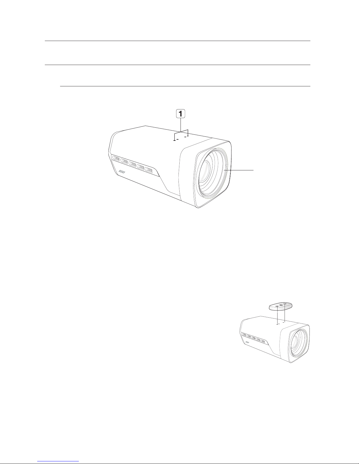
COMPONENT NAMES AND FUNCTIONS
a
Camera Holder (Mount) Holes
Used when you mount the camera onto the
bracket by fixing the camera holder (mount)
adaptor with the bracket.
bZoom Lens
Built-in zoom lens.
FRONT SIDE
b
`Attach the holder to the top of the camera. Use screws
included in the package or their equivalent. Otherwise, the
holder may not assemble to the camera properly.
`Wipe out a dirty surface of the lens softly with a lens tissue or
cloth to which you have applied ethanol.
M
English_13
●introduction
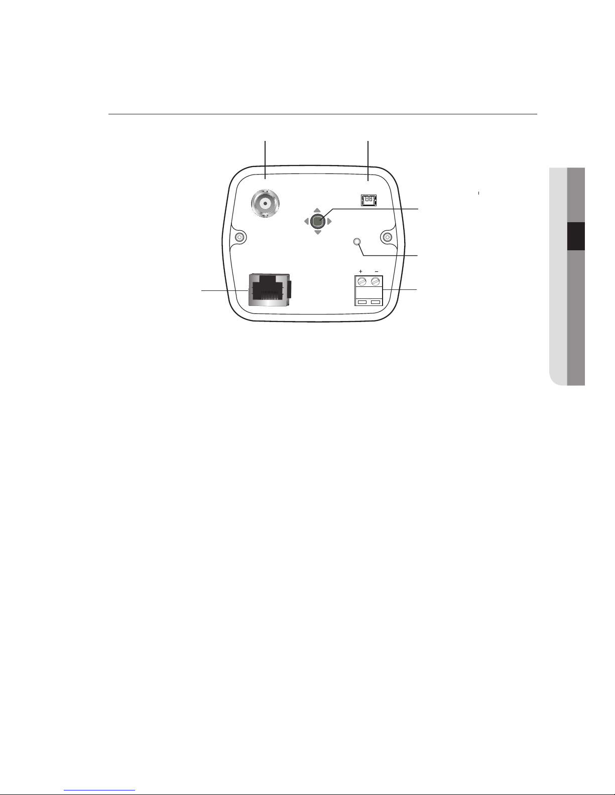
REAR SIDE
aAHD Jack
Sends video signal and connects to the Video IN port of a AHD DVR.
bCVBS Jack
Analog video output port. (for installation)
cFunction Setup switch
Press the Function Setup switch to display the menu screen. After the menu is
displayed on the screen, move the cursor <up/down/left/right> to select the desired
item or to change the value or status.
Also, moving the cursor up/down/left/right to control zoom, focus, and auto focus
functions.
moving the cursor down : To widen the view. (ZOOM OUT)
moving the cursor up : To close in on a far object. (ZOOM IN)
moving the cursor left : To see a near object clearly.
moving the cursor right : To see a far object clearly.
dPower LED
Illuminates when power is supplied.
ePower Input Terminal
Power supply terminal (DC12V±10%)
f RJ-45 JACK
Terminals, such as RS-485 communications, MD OUT, ZOOM, and FOCUS, EX_DN
are included.
POWER
DC 12V
AHD CVBS
EX_DN
GND
MD
COM
FOCUS
ZOOM
RS-485 -
RS-485 +
b
c

connection
14_ connection
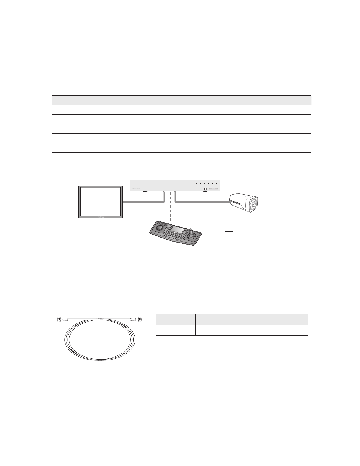
CONNECTING TO MONITOR
Refer to the following figure to connect monitors through DVR.
yAs the connecting method varies with the instruments, refer to the manual
supplied with the instrument.
yOnly connect the cable when the power is turned off.
CONNECTING TO POWER
You can connect power as shown in the following figure.
`Use of an excessively long adaptor output
line for connection to the camera may affect
the performance of the camera.
`Standard voltage for camera operation : DC12V ±
10%
`The wire is polarized. Match ‘+’ and ‘-’
terminals properly.
REC HDD ALARM
NETWORK BACKUP
POWER
HCZ-6320
AHD DVR
Monitor
POWER
DC 12V
AHD CVBS
EX_DN
GND
MD
COM
FOCUS
ZOOM
RS-485 -
RS-485 +
English_17
POWER
DC 12V
AHD CVBS
EX_DN
GND
MD
COM
FOCUS
ZOOM
RS-485 -
RS-485 +
M

English_15
●connection
When the resistance value of copper wire is at [20°C(68°F)]
Copper wire size (AWG) #24 (0.22mm2)#22 (0.33mm2)#20 (0.52mm2)#18 (0.83mm2)
Resistance value(Ω/m) 0.078 0.050 0.030 0.018
Voltage Drop (V/m) 0.028 0.018 0.011 0.006
yAs shown in the table above, voltage decreases as the wire gets longer.
Therefore use of an excessively long adaptor output line for connection to the cam-
era may affect the performance of the camera.
❈
Standard voltage for camera operation : DC 12V±10%
❈
There may be some deviation in voltage drop depending on the type of wire and the
manufacturer.
MM
`Be sure to connect power only after all the installation is complete.
CONTROL VIA RS-485 INTERFACE
The camera can be controlled by using external controllers like a Remote controller. (RS-
485 Communication)
(1) To control by PC
Connect the RS-485 control port of the camera and the serial cable through an RS-485
converter.
Example) PC Serial Port Serial Cable RS-485 Converter Camera RS-485 Control
Port.
(2) To control using a DVR or System Controller
Connect the RS-485 cable (TRX+, TRX-) to the connection port of the 485 control board
that is connected to the DVR or System Controller.
485 Control Board Connection Port RS-485 Control Port
(+) CONNECTION TERMINAL (TRX+) 485+
(-) CONNECTION TERMINAL (TRX-) 485-
* RS-485 Communication establishment initial value
Item Camera ID BAUD RATE UART MODE RET PKT
Initial value 19600 8-NONE-1 ENABLE
MM
`To control the camera by constructing an additional controller, use the Samsung-T/E,
Pelco-D/P, Panasonic, Bosch, AD, Vicon, Honeywell.
connection
16_ connection
USING COAXIAL COMMUNICATIONS
• Coaxial Communications System
• OSD Control method
CAMERA DVR CONTROLLER
SET MENU/ENTER OSD KEY
UP UP KEY JOYSTICK UP
DOWN DOWN KEY JOYSTICK DOWN
LEFT LEFT KEY JOYSTICK LEFT
RIGHT RIGHT KEY JOYSTICK RIGHT
• Video Cable
The camera's video output port is connected to the monitor with a BNC coaxial
cable, shown below : If the distance between the camera and the monitor exceeds
the recommended maximum, please use an auxiliary video amp.
Distance Recommended Cable Specification
500m 5C2V
MM
`It is recommended that pure copper coax cable is used and not copper coated
steel, as this will cause issues with the communication over the coaxial cable.
MENU
SEARCH
MUL
TI
REC
MENU
PRESET
GROUP
TRACK
CAM
12345
67890
MON
CLOSE OPEN
NEAR FAR
WIDE TELE
PTZ DVR MTX SETUP
ESC
FUNC ENTER
REC HDD ALARM
NETWORK BACKUP
POWER
<DVR>
• : BNC
•---- : RS-485
<CONTROLLER>
English_17
●connection
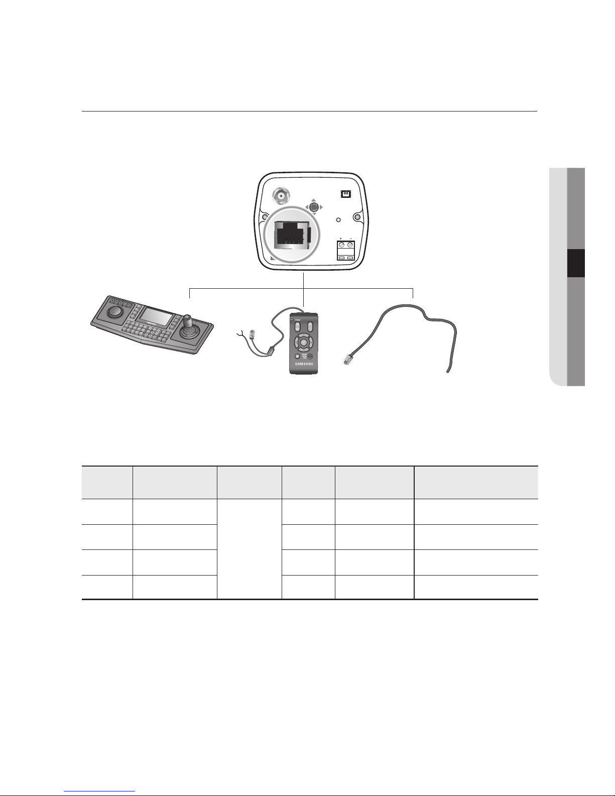
CONNECTING TO 8P CONTROL TERMINAL
The camera can be controlled by using external controllers like a Remote
controller. (RS-485 Communication)
* 8P Control Terminal Configuration
SPC-6000
8-Pin CABLE ASSY
SPC-200
MENU
SEARCH
MULTI
REC
MENU
PRESET
GROUP
TRACK
CAM
12345
67890
MON
CLOSE OPEN
NEAR FAR
WIDE TELE
PTZ DVR MTX SETUP
ESC
FUNC ENTER
POWER
DC 12V
AHD CVBS
EX_DN
MD
GND
GND
FOCUS
ZOOM
RS-485+
RS-485 -
Name Cable color
Description
Name Cable color Description
ZOOM ORANGE
-
GND BLUE -
FOCUS
WHITE/ORANGE
EX DN WHITE/BLUE External D/N
COM GREEN 485+ BROWN RS-485 communication
MD
WHITE/GREEN
485-
WHITE/BROWN
RS-485 communication
connection
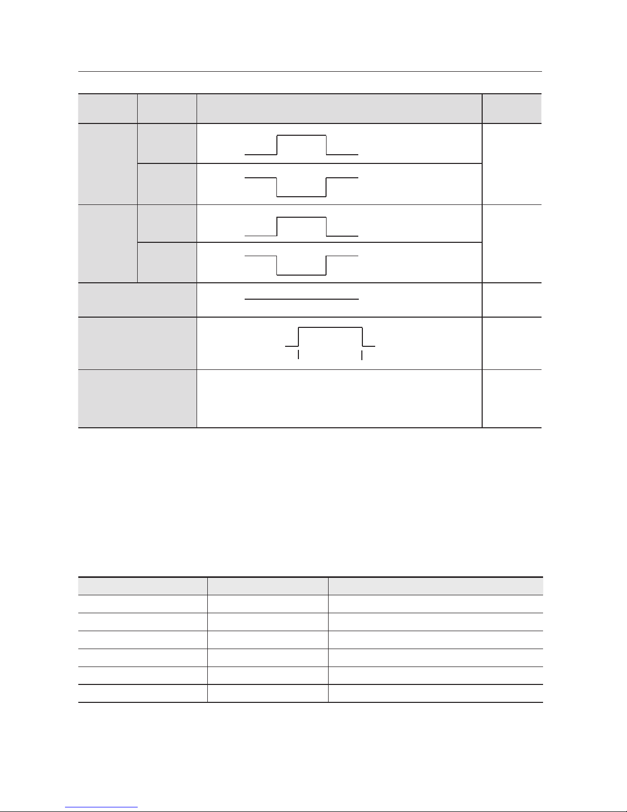
18_ connection
Connecto
r
Function Signal Level I/O
ZOOM
Tele
+6V ~ +12V
COM
I
Wide
-6V ~ -12V
COM
FOCUS
Far
+6V ~ +12V
COM
I
Near
-6V ~ -12V
COM
COM
COM
-
MD
USER Vcc
0V
3±0.5sec
←→
O
EX DN
DAY mode : D&N terminals must be OPEN to external signals.
(Do not input voltage)
NIGHT mode : D&N terminal must be connected to the ground
I
MM
`MD(Motion Detection) Output format is open collector.
`When using the MD function, the 'GND' should be connected to the frame ground.
`Do not simultaneously connect the RS-485 (+) (-) communication line when you
use voltage control ZOOM and FOCUS, using the RECEIVER BOX (SRX-100B).
* Match the communication setup between devices when you use the wired
controller (SPC-200) or SPC-6000.
ITEM SPC-200 SPC-6000(Factory Default)
MODE Serial Serial
Data Bit 8 bit 8 bit
Bit/Sec 9600bps 9600bps
Parity EVEN NONE
CAM ID NO. 01~255
RETURN PACKET ENABLE See the SPC-6000 manual
There is no motion There is motion
MM
`Contact an authorized technician for inspection.

English_19
●Camera OperatiOn
MENU CONFIGURATION
camera operation
MAIN SETUP MENU
SSDR ● ON
●OFF
WHITE BAL
● ATW
●MANUAL
● AWC→SET
●OUTDOOR ●INDOOR
● MERCURY
●SODIUM
BACKLIGHT ●OFF
●BLC
●HLC
● WDR
INTELLIGENCE ●OFF
●ON
FOCUS
● MODE
●ZOOM TRACK
●ZOOM SPEED
●D-ZOOM
●ZOOM POS INIT
●USER PRESET
●LENS INIT
●RETURN
EXPOSURE ●BRIGHTNESS
●IRIS
●SHUTTER
●AGC
●SSNR
●RETURN
SPECIAL
●PRIVACY
●DAY/NIGHT
●DIS
●DEFOG
●COMM ADJ
●IMAGE ADJ
●DISPLAY
●RETURN
RESET
EXIT

20_ camera operation
camera operation
MENU SETUP
Use Function Setup switch on back of the camera.
1.
Press
Function Setup switch
for 3 seconds.
• Main setup menu is displayed on the monitor screen.
2. Select a desired function using the Function Setup switch
• Place the cursor over a desired item.
3. Set up a selected item by using the Function Setup switch.
4. To finish the setting, select ‘EXIT’ and press the Function Setup switch.
MM
`An item with the icon also has sub menus. To select a sub menu,
select an item with the icon and press the Function Setup switch.
`An item with the --- icon is unavailable due to function settings.
MAIN SETUP
SSDR ON
WHITE BAL ATW
BACKLIGHT OFF
INTELLIGENCE OFF
FOCUS
EXPOSURE
SPECIAL
RESET
EXIT
Change the status
using the Function
Setup switch.
Select the
function using
the Function
Setup switch.
POWER
DC 12V
AHD CVBS
EX_DN
GND
MD
COM
FOCUS
ZOOM
RS-485 -
RS-485 +
Function Setup switch
This manual suits for next models
2
Table of contents


