Hanwha Techwin Wisenet SMT-1030PV User manual

PUBLIC VIEW MONITOR
SMT-1030PV
SMT-2730PV
SMT-3230PV

SAFETY INSTRUCTIONS
1. WARNING
To reduce the risk of fire or electric shock, do not expose this product to rain or moisture.
Do not insert any metallic object through the ventilation grills or other openings on the equipment.
Apparatus shall not be exposed to dripping or splashing and that no objects filled with liquids, such as vases,
shall be placed on the apparatus.
To prevent injury, this apparatus must be securely attached to the Wall/ceiling in accordance with the installa-
tion instructions.
2. CAUTION
CAUTION
RISK OF ELECTRIC
SHOCK DO NOT OPEN
CAUTION
: TO REDUCE THE RISK OF ELECTRIC SHOCK,
DO NOT REMOVE REAR COVER. NO USER SERVICEABLE
PARTS INSIDE. REFER TO QUALIFIED SERVICE PERSONNEL.
3. EXPLANATION OF GRAPHICAL SYMBOLS
The lightning flash with arrowhead symbol, within an equilateral triangle, is intended to
alert the user to the presence of “dangerous voltage: within the product’s enclosure
that may be of sufficient magnitude to constitute a risk of electric shock to persons.
The exclamation point within an equilateral triangle is intended to alert the user to
the presence of important operating and maintenance (servicing) instructions in the
literature accompanying the product.
※Select an installation site that can hold at least 4 times the monitor weight.

English _3
CONTENTS
OVERVIEW
4
4Package Contents
5Names and functions of each part
9Remote control
MENU SETTINGS
10
10 OSD Menu setting
16 Camera setup
NETWORK CONNECTION AND SETUP &
WEBVIEWER
17
17 Connecting the PVM Directly to Local Area
Networking
18 Connecting the PVM Directly to a DHCP
Based DSL/Cable Modem
19 Using Device Manager
19 Automatically searching camera
19 Configuring IP address
21 Manually registering camera
22 Automatically configuring IP
22 Port Range Forward (Port Mapping) Setup
24 Connecting to the Camera from a Shared
Local PC
24 Connecting to the Camera from a Remote
PC via the Internet
24 Connecting to the Camera
26 Password setting
26 Login
26 Camera Web Viewer Setup
SETUP SCREEN
27
27 Setup
27 Creating a text overlay
28 Setting slide show
30 Setting alarm input
APPENDIX
33
33 Mechanical
36 Troubleshooting

4_ overview
overview
PACKAGE CONTENTS
Please check the following contents are included in addition to the main unit.
Public View Monitor User Manual Warranty card Power Cable
Adapter Remote Controller Battery Terminal Block
Ferrite Core
(SMT-1030PV only)
overview

English _5
NAMES AND FUNCTIONS OF EACH PART
SMT-1030PV(10")
Front
➊ ➋ ➌
Name
Description of functions
➊
Camera Lens TNB-6030 camera is installed.
➋
IR Receiver Receive IR signal from Remote Controller.
➌
LED
Displays the power ON/OFF status.
ON – GREEN
OFF – RED

6_ overview
overview
Back
➊ ➋ ➌ ➍
➎
Name
Description of functions
➊
DC 12V This is the power input terminal.
➋
ALARM ALARM signal input / output
➌
Micro SD Compartment for the Micro SD card.
➍
PoE Power of Ethernet(802.3at)
➎
RESET Resets the camera installed in the monitor to its factory default settings.
` If you forget your password, use the RESET button.
M ` Wrap the ferrite core provided as an accessory two times around the LAN cable.

English _7
SMT-2730PV(27") / 3230PV(32")
Front
➊ ➋ ➌
Name
Description of functions
➊
Camera Lens TNB-6031 camera is installed.
➋
IR Receiver Receive IR signal from Remote Controller.
➌
LED
Displays the power ON/OFF status.
ON – GREEN
OFF – RED

8_ overview
overview
Back
➊
➋
➌
➍
➎
➏
➐
Name
Description of functions
➊
HDMI HDMI input terminal.
➋
USB Connects the USB devices.
➌
DC 12V This is the power input terminal.
➍
ALARM ALARM signal input / output
➎
NETWORK Used to connect the Ethernet cable for network connection.
➏
Micro SD Compartment for the Micro SD card.
➐
RESET Resets the camera installed in the monitor to its factory default settings.
` If you forget your password, use the RESET button.

English _9
REMOTE CONTROL
HDMI2/CAMERA
Select CAMERA mode
(SMT-2730PV/SMT-3230PV only)
SCAN MODE
Select the scan mode of the screen
MENU/EXIT
Activate and exit the OSD menu
HDMI
Select HDMI mode
(SMT-2730PV/SMT-3230PV only)
POWER
Turn ON / OFF the monitor
COLOR TEMP
Select color temperature of the screen
S.SET
Toggle source (HDMI/CAMERA)
(SMT-2730PV/SMT-3230PV only)
M ` Those buttons without specific description are deprecated buttons.
10_ menu settings
menu settings
OSD MENU SETTING
MENU STRUCTURE
When user presses the menu key, the first “PICTURE” menu is displayed. Select by “◀”
key then two types of menu functions are shown as below.
• PICTURE ( ) : Menu related to PICTURE Function
• OPTION ( ) : Other OSD Menu Status Control and Firmware Update
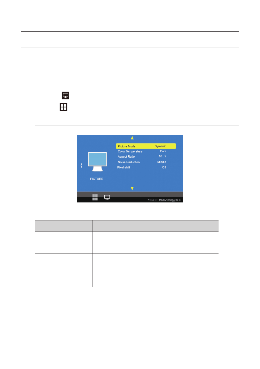
PICTURE MENU
The PICTURE Menu can be selected from the following 5 modes by pressing the ▲ or ▼ key.
functions Description
Picture Mode Adjust setting of the picture
Color Temperature Change color according to the color temperature
Aspect Ratio Change the aspect ratio
Noise Reduction Adjust noise attenuation of input signal
Pixel shift Select auto pixel shift

English _11
Picture Mode
Picture Mode can select 4 modes as Mild, Dynamic, Standard and User as shown in the figure
below. Press the "◀, ▶" key to change the mode.
Picture Mode Standard
Contrast 50
Brightness 50
Color 50
Sharpness 50
Tint 50
MENU
Picture Mode Mild
Contrast 45
Brightness 48
Color 45
Sharpness 50
Tint 50
MENU
Picture Mode User
Contrast 60
Brightness 50
Color 60
Sharpness 60
Tint 50
MENU
Picture Mode Dynamic
Contrast 60
Brightness 50
Color 60
Sharpness 60
Tint 50
MENU
Three of the four modes except for User mode are shipped with fixed values at the time of shipment
from the factory.
User mode can be set with “◀, ▶” keys by selecting each item below with “▲, ▼” key only in the
User mode.
Contrast Adjust difference in the color and brightness
Brightness Adjust the dark and light
Color Adjust for desired color intensity
Sharpness Adjust for best clarity of outline detail
Tint Adjust for natural flesh tones
Color Temperature
Color Temperature can select 4 modes as Cool, Medium, Warm and User as shown in the figure
below.
Color Tempera.. Cool
Red 45
Green 44
Blue 11
MENU
Color Tempera.. Medium
Red 48
Green 44
Blue 2
MENU
Color Tempera.. Warm
Red 51
Green 44
Blue 100
MENU
Color Tempera..
User
Red 50
Green 50
Blue 50
MENU
Three modes except User mode are factory shipped with factory default values, and each color item
(Red, Green, Blue) is selected with the “▲, ▼” keys in the User mode only.
User settings are available.

12_ menu settings
menu settings
Aspect Ratio
Aspect Ratio allows user to select the each aspect ratio as shown in the figure below.
(However, activated list is according to the input port and the input resolution.)
Aspect Ratio
Auto
4 : 3
16 : 9
Zoom 1
Zoom 2
Just Scan
MENU
Noise Reduction
Noise Reduction can select 5 modes as Off, Low, Middle, High, Default as shown in the figure below.
Noise Reduction
Off
Low
Middle
High
Default
MENU
Pixel shift
Select auto pixel shift (On, Off)

English _13
OPTION MENU
The Option Menu can be selected from the following 7 modes by pressing the ▲ or ▼ key.
functions Description
OSD Language Selectable OSD Menu Language
Blending Adjust blending for OSD Menu and Main window
OSD Duration Setting Duration time of OSD Menu
Restore Factory Default Resets the monitor to its factory default settings.
Software Update Updates the monitor.

14_ menu settings
menu settings
OSD Language
As shown in the figure below, OSD Language can be selected by “▲, ▼” key.
OSD Language
English
Espaol
Franais
Deutsch
Italiano
MENU
M ` Press the EXIT button to exit the Setup screen. Then, the language will be changed to the selected
language.
Blending
OSD Menu Blending can select 4 modes as Off, Low, Middle, High by pressing
the “ENTER” key.
OSD Duration
OSD menu Duration can select 4 modes as 5, 10, 15Sec and Off by pressing
the “ENTER” key.
Restore Factory Default
Restore factory default can be selected by pressing the "ENTER" key. Select Yes or No by
the “◀, ▶” key.
◀Yes No ▶
Are you sure?

English _15
Software Update(Monitor)
Software update default can be selected by pressing the "MENU" key. Select Yes or No by
the “◀, ▶” key.
Software Update
48%
◀Yes No ▶
Are you sure?
M ` See below for more information on how to update software for each model:
-SMT-1030PV: You can update it using a Micro SD card that can be inserted into the Micro SD card port
inside the product.
-SMT-2730PV/SMT-3230PV: You can update it using a USB that can be connected through the external
USB port.

16_ menu settings
menu settings
CAMERA SETUP
Supported video modes
You can use various video modes, and some video modes need to be set up in the camera web viewer.
Still image
Live video
You can see images with Still image.You can watch a live monitoring feed.
Recording in Progress
HDMI input
Video is displayed through HDMI input.
(SMT-2730PV/SMT-3230PV only)
When motion is detected, the screen mode changes from Still image to Live video.
Motion
detection
Slide show & Live video
Screen transition
after set Dwell
time
Recording in Progress
M ` See the camera manual for more information on recording.

English _17
network connection and setup & webviewer
You can set up the network settings according to your network configurations.
CONNECTING THE PVM DIRECTLY TO LOCAL AREA NETWORKING
Connecting to the PVM from a local PC in the LAN
1. Launch an Internet browser on the local PC.
2. Enter the IP address of the PVM in the address bar of the browser.
<Local Network>
Local PC
INTERNET
External Remote PC
DDNS Server
(Data Center, KOREA)
M ` A remote PC in an external Internet out of the LAN network may not be able to connect to the PVM installed
in the intranet if the port-forwarding is not properly set or a firewall is set.
In this case, to resolve the problem, contact your network administrator.
` By factory default, the IP address will be assigned from the DHCP server automatically.
If there is no DHCP server available, the IP address will be set to 192.168.1.100.
To change the IP address, use the Device Manager.
For further details on Device Manager use, refer to “Using Device Manager”. (Page 19)

18_ network connection and setup & webviewer
network connection and setup & webviewer
External Remote PC
DDNS Server
(Data Center, KOREA)
DSL/Cable Modem
INTERNET
CONNECTING THE PVM DIRECTLY TO A DHCP BASED DSL/CABLE
MODEM
1. Connect the user PC directly with the PVM.
2. Run the Device Manager and change the IP address of the PVM so that you can use the web
browser on your desktop to connect to the Internet.
3. Use the Internet browser to connect to the web viewer.
4. Move to [Setup] page.
5. Move to [Network] – [DDNS] and configure the DDNS settings.
6. Move to [Basic] – [IP & Port], and set the IP type to [DHCP].
7. Connect the PVM, which was removed from your PC, directly to the modem.
8. Restart the camera.
M ` For information on how to set DDNS, refer to the online help of Web Viewer.
` For information on how to set the IP format, refer to the online help of Web Viewer.

English _19
USING DEVICE MANAGER
M `
Device manager program can be downloaded from <Technical Guides>-<Online Tool> menu at Hanwha
Techwin website (http://www.hanwha-security.com).
`
More instructions of Device Manager can be found at <Help> menu of the main page.
AUTOMATICALLY SEARCHING CAMERA
If a camera is connected to the same network of the PC where device manager is installed, you can find
network camera by using search function.
1. Click <Search> at the main page of device manager.
2. Check the camera from the list.
~Check MAC address at the sticker attached to the camera.
M ` When searching devices in the Device manager, the result of searching 10” is TNB-6030, while the result of
searching 27”/32” is TNB-6031.
CONFIGURING IP ADDRESS
If you want to change camera network setting, <Login OK> sign must be displayed at <Status>. Click
<Authentication> at the main page to log in.
Configuring Static IP
Manually insert and configure IP address & port information.
1. Click the camera from the list that you want the change the
IP setting.
2. Click <IP Assign> at the main page of device manager.
3. Select <Assign the following IP address>.
~IP information of the camera will be displayed as previously
set.
4. Fill in IP & Port related categories.
If not using a Broadband Router
For setting <IP Address>, <Subnet Mask>, and <Gateway>, contact your network administrator.
~HTTP Port : Used to access the camera using the Internet browser, defaulted to 80.
~RTSP Port: A port that controls real-time streaming. The initial value is 554.

20_ network connection and setup & webviewer
network connection and setup & webviewer
If using a Broadband Router
~IP Address : Enter an address falling in the IP range provided
by the Broadband Router.
ex) 192.168.1.2~254, 192.168.0.2~254,
192.168.XXX.2~254
~Subnet Mask : The <Subnet Mask> of the Broadband
Router will be the <Subnet Mask> of the camera.
~Gateway : The <Local IP Address> of the Broadband Router
will be the <Gateway> of the camera.
M ` The settings may differ depending on the connected Broadband Router model.
For more information, refer to the user manual of the applicable router.
` For more information about port forwarding of the broadband router, refer to “Port Range Forward (Port
Mapping) Setup”. (Page 22)
If the Broadband Router has more than one camera connected
Configure the IP related settings and the Port related settings distinctly with each other.
ex)
Category Camera #1 Camera #2
IP related settings
IP Address
Subnet Mask
Gateway
192.168.1.100
255.255.255.0
192.168.1.1
192.168.1.101
255.255.255.0
192.168.1.1
Port related settings HTTP Port
RTSP Port
8080
554
8081
555
M ` If the <HTTP Port> is set other than 80, you must provide the <Port> number in the address bar of the
Internet browser before you can access the camera.
ex) http://IP address : HTTP Port
http://192.168.1.100:8080
5. Click [Apply] Button.
6. If the success message is displayed, click [OK].
This manual suits for next models
2
Table of contents
Other Hanwha Techwin Monitor manuals


