Harbor Freight Tools CENTRAL MACHINERY 91966 User manual

®
ASSEMBLY AND OPERATING INSTRUCTIONS
3491 Mission Oaks Blvd., Camarillo, CA 93011
Visit our Web site at: http://www.harborfreight.com
Copyright©2004 by Harbor Freight Tools®. All rights reserved. No portion of this
manual or any artwork contained herein may be reproduced in any shape or form
without the express written consent of Harbor Freight Tools.
For technical questions and replacement parts, please call 1-800-444-3353.
TO PREVENT SERIOUS INJURY,
READ AND UNDERSTAND ALL WARNINGS
AND INSTRUCTIONS BEFORE USE.
ELECTRIC BRAKE WASHER
WITH PUMP
Model 91966

SKU 91966 For technical questions, please call 1-800-444-3353. Page 2
PRODUCT SPECIFICATIONS
SAVE THIS MANUAL
You will need this manual for the safety warnings and precautions, assembly,
operating, inspection, maintenance and cleaning procedures, parts list and as-
sembly diagram. Keep your invoice with this manual. Write the invoice number
on the inside of the front cover. Keep this manual and invoice in a safe and dry
place for future reference.
GENERAL SAFETY RULES
WARNING!
READ AND UNDERSTAND ALL INSTRUCTIONS
Failure to follow all instructions listed below may result in
electric shock, fire, and/or serious injury.
SAVE THESE INSTRUCTIONS
WORK AREA
1. Keep your work area clean and well lit. Cluttered benches and dark areas
invite accidents.
2. Do not operate power tools in explosive atmospheres, such as in the
presence of flammable liquids, gases, or dust. Power tools create sparks
which may ignite the dust or fumes.
3. Keep bystanders, children, and visitors away while operating a power tool.
Distractions can cause you to lose control. Protect others in the work area and
nearby objects from Brake Fluid spatter. Provide barriers or shields as needed.
Flow Rate 5 Gallons/Hour
Tank Size 20” L x 14-1/2” W x 4-1/2” D
Tray Size 19-5/8” x 14-1/4” x 3-7/8”
Screen Size 11-3/4” x 8-1/4”
Tank Capacity 6 Gallons
Features: 90° Drain Tank Fitting, 4 Swivel Casters,
Fully Enclosed Electric Recirculating Pump.

SKU 91966 For technical questions, please call 1-800-444-3353. Page 3
ELECTRICAL SAFETY
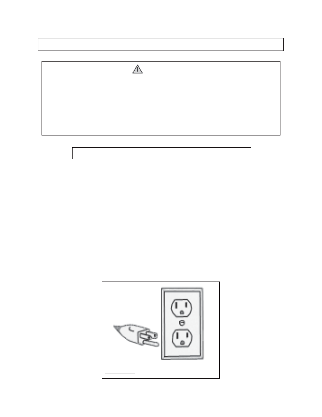
4. Grounded tools must be plugged into an outlet properly installed and
grounded in accordance with all codes and ordinances. Never remove the
grounding prong or modify the plug in any way. Do not use any adapter
plugs. Check with a qualified electrician if you are in doubt as to whether
the outlet is properly grounded. If the tools should electrically malfunction or
break down, grounding provides a low resistance path to carry electricity away
from the user.
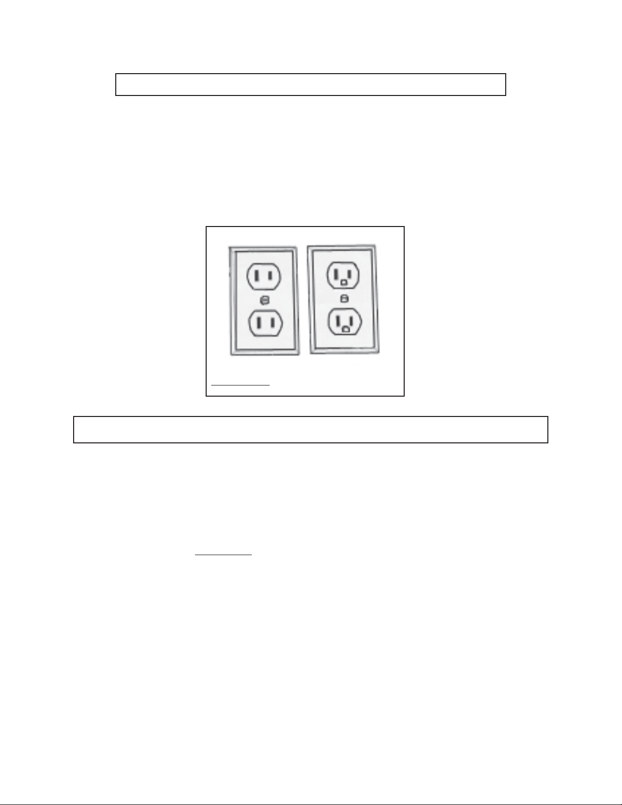
5. Double insulated tools are equipped with a polarized plug (one blade is
wider than the other). This plug will fit in a polarized outlet only one way. If
the plug does not fit fully in the outlet, reverse the plug. If it still does not
fit, contact a qualified electrician to install a polarized outlet. Do not
change the plug in any way. Double insulation eliminates the need for the
three wire grounded power cord and grounded power supply system.
6. Avoid body contact with grounded surfaces such as pipes, radiators,
ranges, and refrigerators. There is an increased risk of electric shock if your
body is grounded.
7. Do not expose power tools to rain or wet conditions. Water entering a power
tool will increase the risk of electric shock.
8. Do not abuse the Power Cord. Never use the Power Cord to carry the tools
or pull the Plug from an outlet. Keep the Power Cord away from heat, oil,
sharp edges, or moving parts. Replace damaged Power Cords immedi-
ately. Damaged Power Cords increase the risk of electric shock.
9. When operating a power tool outside, use an outdoor extension cord
marked “W-A” or “W”. These extension cords are rated for outdoor use, and
reduce the risk of electric shock.
PERSONAL SAFETY
10. Stay alert. Watch what you are doing, and use common sense when oper-
ating a power tool. Do not use a power tool while tired or under the influ-
ence of drugs, alcohol, or medication. A moment of inattention while operat-
ing power tools may result in serious personal injury.
11. Dress properly. Do not wear loose clothing or jewelry. Contain long hair.
Keep your hair, clothing, and gloves away from moving parts. Loose clothes,
jewelry, or long hair can be caught in moving parts. Wearing a long-sleeved shirt
is recommended when using this item.

SKU 91966 For technical questions, please call 1-800-444-3353. Page 4
12. Avoid accidental starting. Be sure the Power Switch is off before plugging
in.
13. Remove adjusting keys or wrenches before turning the power tool on. A
wrench or a key that is left attached to a rotating part of the power tool may result
in personal injury.
14. Do not overreach. Keep proper footing and balance at all times. Proper
footing and balance enables better control of the power tool in unexpected
situations.
15. Use safety equipment. Always wear eye protection. Dust mask, non-skid
safety shoes, hard hat, or hearing protection must be used for appropriate
conditions.
TOOL USE AND CARE
16. Do not force the tool. Use the correct tool for your application. The correct
tool will do the job better and safer at the rate for which it is designed.
17. Do not use the power tool if the Power Switch does not turn it on or off.
Any tool that cannot be controlled with the Power Switch is dangerous and must
be replaced.
18. Disconnect the Power Cord Plug from the power source before making any
adjustments, changing accessories, or storing the tool. Such preventive
safety measures reduce the risk of starting the tool accidentally.
19. Store idle tools out of reach of children and other untrained persons. Tools
are dangerous in the hands of untrained users.
20. Maintain tools with care. Do not use a damaged tool. Tag damaged tools “Do
not use” until repaired.
21. Check for misalignment or binding of moving parts, breakage of parts, and
any other condition that may affect the tool’s operation. If damaged, have
the tool serviced before using. Many accidents are caused by poorly main-
tained tools.

SKU 91966 For technical questions, please call 1-800-444-3353. Page 5
22. Use only accessories that are recommended by the manufacturer for your
model. Accessories that may be suitable for one tool may become hazardous
when used on another tool.
SERVICE
23. Tool service must be performed only by qualified repair personnel. Service
or maintenance performed by unqualified personnel could result in a risk of injury.
24. When servicing a tool, use only identical replacement parts. Follow
instructions in the
“Inspection, Maintenance, And Cleaning”
section of this
manual. Use of unauthorized parts or failure to follow maintenance instructions
may create a risk of electric shock or injury.
SPECIFIC SAFETY RULES
1. Maintain labels and nameplates on the Brake Washer. These carry important
information. If unreadable or missing, contact Harbor Freight Tools for a
replacement.
2. Always wear ANSI approved, splash resistant, safety impact eye goggles
and heavy work gloves when using the Brake Washer. Using personal
safety devices reduce the risk for injury. Safety impact eye goggles and heavy
work gloves are available from Harbor Freight Tools.
3. Maintain a safe working environment. Keep the work area well lit. Make sure
there is adequate surrounding workspace. Always keep the work area free of
obstructions, grease, oil, trash, and other debris. Do not use a power tool in
areas near flammable chemicals, dusts, and vapors. Do not use this product in a
damp or wet location.
4. Avoid unintentional starting. Make sure you are prepared to begin work
before plugging in the Brake Washer.
5. Do not over- or underfill the Brake Washer.
6. Never leave the Brake Washer unattended when it is plugged into an elec-
trical outlet. Turn off the tool, and unplug it from its electrical outlet before
leaving. Always unplug the Brake Washer from its electrical outlet before
performing any inspection, maintenance, or cleaning procedures.
7. Never use flammable solvents, gasoline, diesel fuel, or any other non-
approved liquid to clean brakes. Only use Brake Cleaning fluid specifically
designed for this purpose. Using any other fluid can result in reduced brak-
ing efficiency or BRAKE FAILURE.

SKU 91966 For technical questions, please call 1-800-444-3353. Page 6
GROUNDING
WARNING!
Improperly connecting the grounding wire can result in the risk of electric
shock. Check with a qualified electrician if you are in doubt as to whether the
outlet is properly grounded. Do not modify the power cord plug provided with
the tool. Never remove the grounding prong from the plug. Do not use the
tool if the power cord or plug is damaged. If damaged, have it repaired by
a service facility before use. If the plug will not fit the outlet, have a proper
outlet installed by a qualified electrician.
GROUNDED TOOLS: TOOLS WITH THREE PRONG PLUGS
1. Tools marked with “Grounding Required” have a three wire cord and three prong
grounding plug. The plug must be connected to a properly grounded outlet. If
the tool should electrically malfunction or break down, grounding provides a low
resistance path to carry electricity away from the user, reducing the risk of elec-
tric shock. (See Figure A.)
2. The grounding prong in the plug is connected through the green wire inside the
cord to the grounding system in the tool. The green wire in the cord must be the
only wire connected to the tool’s grounding system and must never be attached
to an electrically “live” terminal. (See Figure A.)
3. Your tool must be plugged into an appropriate outlet, properly installed and
grounded in accordance with all codes and ordinances. The plug and outlet
should look like those in the following illustration. (See Figure A.)
FIGURE A

SKU 91966 For technical questions, please call 1-800-444-3353. Page 7
FIGURE B
DOUBLE INSULATED TOOLS: TOOLS WITH TWO PRONG PLUGS
4. Tools marked “Double Insulated” do not require grounding. They have a special
double insulation system which satisfies OSHA requirements and complies with
the applicable standards of Underwriters Laboratories, Inc., the Canadian
Standard Association, and the National Electrical Code. (See Figure B.)
5. Double insulated tools may be used in either of the 120 volt outlets shown in the
following illustration. (See Figure B.)
EXTENSION CORDS
1.
Grounded
tools require a three wire extension cord.
Double Insulated
tools
can use either a two or three wire extension cord.
2. As the distance from the supply outlet increases, you must use a heavier gauge
extension cord. Using extension cords with inadequately sized wire causes a
serious drop in voltage, resulting in loss of power and possible tool damage.
(See Figure C, next page.)
3. The smaller the gauge number of the wire, the greater the capacity of the cord.
For example, a 14 gauge cord can carry a higher current than a 16 gauge cord.
(See Figure C.)
4. When using more than one extension cord to make up the total length, make
sure each cord contains at least the minimum wire size required.
(See Figure C.)
5. If you are using one extension cord for more than one tool, add the nameplate
amperes and use the sum to determine the required minimum cord size.
(See Figure C.)

SKU 91966 For technical questions, please call 1-800-444-3353. Page 8
6. If you are using an extension cord outdoors, make sure it is marked with the
suffix “W-A” (“W” in Canada) to indicate it is acceptable for outdoor use.
7. Make sure your extension cord is properly wired and in good electrical condition.
Always replace a damaged extension cord or have it repaired by a qualified
electrician before using it.
8. Protect your extension cords from sharp objects, excessive heat, and damp or
wet areas.
SYMBOLOGY
Double Insulated
Canadian Standards
Association
Underwriters
Laboratories, Inc.
Volts Alternating Current
Amperes
No Load Revolutions
per Minute (RPM)
noxxxx/min.
A
V ~
RECOMMENDED MINIMUM WIRE GAUGE FOR EXTENSION CORDS*
(120 VOLT)
NAMEPLATE
AMPERES
(At Full Load)
EXTENSION CORD LENGTH
25 FEET 50 FEET 75 FEET 100 FEET 150 FEET
0 - 2.0 18 18 16 16 16
2.1 - 3.4 18 18 16 14 14
3.5 - 5.0 18 18 16 14 12
5.1 - 7.0 18 16 14 12 12
7.1 - 12.0 16 14 12 10 -
12.1 - 16.0 14 12 10 - -
16.1 - 20.0 12 10 - - -
FIGURE C *Based on limiting the line voltage drop
to five volts at 150% of the rated amperes.

SKU 91966 For technical questions, please call 1-800-444-3353. Page 9
UNPACKING
When unpacking, check to make sure all the parts shown on the Parts List on page 13
are included. If any parts are missing or broken, please call Harbor Freight Tools at the
number shown on the cover of this manual as soon as possible.
ASSEMBLY AND OPERATING INSTRUCTIONS
NOTE: For additional information regarding the parts listed in the following pages, refer
to the Assembly Diagram on page 14.
1. CAUTION: Always make sure the Power Cord (12) of the Brake Washer is un-
plugged from its electrical outlet
prior
to assembling or making any adjustments
to the tool.
2. Attach the two Casters (17), and the two Casters With Brakes (16) to the four
metal brackets on the bottom of the unit. Using a wrench (not included), secure
them with Washers (27) and Nuts (26). See the Assembly Drawing on page 14
and FIGURE 1 below.
3. Fit the Elbow (18) onto the right side of the Tank (29). Insert and thread the Ball
Valve (19) into the Elbow (18). See the Assembly Drawing on page 14 and
FIGURE 1 below.
FIGURE 1
Caster (17)
Caster With Brake (16)
Nut (26)
Hose (8)
Latch
Tank (29)
Lid (15)
Ball Valve (19)
Hose Connector (9)
Brake

SKU 91966 For technical questions, please call 1-800-444-3353. Page 10
ASSEMBLY AND OPERATING INSTRUCTIONS (continued)
4. Place the Brace Pipe B (6) onto the center hole of the Lid (15) and insert four
Pan Screws (23) through the top, securing it with Spring Washers (24) and Nuts
(25), from the bottom. See the Assembly Drawing on page 14 and FIGURES 2
and 3 below.
5. Insert Brace Pipe A (5) into Brace Pipe B (6), and secure it by inserting and
tightening the Pipe Screw (20). See the Assembly Drawing on page 14 and
FIGURE 2.
6. Attach the Pump Connector (11) to the Pump (12). See FIGURE 3.
7. Secure the Hose (8) to the Hose Connector (9) with a Hose Clamp (22). See the
Assembly Drawing on page 14.
8. Place the Lid (15) on the Tank (29), making sure the Pump (12) fits in the Pump
Box. See FIGURE 3. Lock both of the Latches (see FIGURE 1).
FIGURE 3FIGURE 2
Spring Washers (24)
and Nuts (25)
Brace Pipe B (6) on
the center hole of
the Lid (15)
Brace
Pipe A (5)
Pipe
Screw (20)
Switch
Pump (12)
Pump Connector (11)
Lid (15)
Pump Box
Tank (29)

SKU 91966 For technical questions, please call 1-800-444-3353. Page 11
ASSEMBLY AND OPERATING INSTRUCTIONS (continued)
9. Thread the Tray (1) onto Brace Pipe A (5). Place the Screen (2) into the Tray (1).
See FIGURE 4.
10. Mount the Brush Holder (3) on one side of the Tray (1) using a Pan Screw (23), a
Spring Washer (24), and a Nut (25). Mount the Power Cord Holder (4) on the
other side using the same hardware. See FIGURE 4 and the Assembly Drawing
on page 14. FIGURE 4
Brush Holder (3)
Brush (7) Power Cord Holder (4)
Brace Pipe A (5)
Screen (2)
Tray (1)
Operation
1. Lock the two Casters With Brakes (16) by depressing the brakes (see FIGURE 1).
2. Release the two Latches and carefully lift the Lid (15). Fill the entire unit up, with
no more or less than 6 Gallons of Brake Cleaning Fluid. Never use flammable
solvents, gasoline, diesel fuel, or any other non-approved liquid to clean
brakes. Only use Brake Cleaning fluid specifically designed for this purpose.
Using other fluids can result in reduced braking efficiency or BRAKE
FAILURE.
3. Adjust the unit to your proper working height by loosening the Pipe Screw (20),
adjusting Brace Pipe A (5), and tightening the Pipe Screw (20).
4. Plug the unit into a power source and turn on the Switch (12) to start fluid running
through the Brush (7). Use the Brush (7) to clean the brake assembly over the
Tray (1). Be careful not to splatter any fluid on nearby people or objects.
5. When finished, turn off the Switch (12), and unplug the unit.

SKU 91966 For technical questions, please call 1-800-444-3353. Page 12
INSPECTION, MAINTENANCE, AND CLEANING
1. WARNING! Make sure the Power Switch (12) of the Brake Washer is in its
“OFF” position and that the tool is unplugged from its electrical outlet before
performing any inspection, maintenance, or cleaning procedures.
2. BEFORE EACH USE, inspect the general condition of the Brake Washer. Check
for loose screws, misalignment or binding of moving parts, cracked or broken
parts, damaged electrical wiring, and any other condition that may affect its safe
operation. If abnormal noise or vibration occurs, have the problem corrected
before further use. Do not use damaged equipment.
3. You may use the same Brake Cleaning Fluid repeatedly if it does not appear too
dirty, and still properly cleans brakes. When performance suffers, or the fluid in
the Tank (29) appears dirty, change the fluid. Contact your local hazardous
waste authority for proper disposal methods and locations.
4. With a dry cloth, wipe down the Screen (2) and the Tray (1) after each use.

SKU 91966 For technical questions, please call 1-800-444-3353. Page 13
THE MANUFACTURER AND/OR DISTRIBUTOR HAS PROVIDED THE PARTS LIST AND ASSEMBLY
DIAGRAM IN THIS MANUAL AS A REFERENCE TOOL ONLY. NEITHER THE MANUFACTURER OR
DISTRIBUTOR MAKES ANY REPRESENTATION OR WARRANTY OF ANY KIND TO THE BUYER THAT
HE OR SHE IS QUALIFIED TO MAKE ANY REPAIRS TO THE PRODUCT, OR THAT HE OR SHE IS
QUALIFIED TO REPLACE ANY PARTS OF THE PRODUCT. IN FACT, THE MANUFACTURER AND/
OR DISTRIBUTOR EXPRESSLY STATES THAT ALL REPAIRS AND PARTS REPLACEMENTS SHOULD
BE UNDERTAKEN BY CERTIFIED AND LICENSED TECHNICIANS, AND NOT BY THE BUYER. THE
BUYER ASSUMES ALL RISK AND LIABILITY ARISING OUT OF HIS OR HER REPAIRS TO THE
ORIGINAL PRODUCT OR REPLACEMENT PARTS THERETO, OR ARISING OUT OF HIS OR HER
INSTALLATION OF REPLACEMENT PARTS THERETO.
PLEASE READ THE FOLLOWING CAREFULLY
PARTS LIST
Part No. Description Qty. Part No. Description Qty.
1 Washing Tray 1 16 Caster With Brake 2
2 Screen 1 17 Caster 2
3 Brush Holder 1 18 Elbow 1
4 Power Cord Holder 1 19 Ball Valve 1
5 Brace Pipe A 1 20 Pipe Screw 1
6 Brace Pipe B 1 21 Nylon Washer 2
7 Brush 1 22 Hose Clamp 2
8 Hose 1 23 Pan Screw 7
9 Hose Connector 1 24 Spring Washer 7
10 Wire Holder 1 25 Nut 7
11 Pump Connector 1 26 Nut 4
12 Pump/Cord/Switch 1 27 Washer 4
13 Filter 1 28 Gasket 2
14 Pump Bracket 1 29 Tank 1
15 Lid 1

SKU 91966 For technical questions, please call 1-800-444-3353. Page 14
NOTE: Some parts are listed and shown for illustration purposes only, and are not
available individually as replacement parts.
ASSEMBLY DIAGRAM
16 19
6
18
6
Table of contents
Popular Washer manuals by other brands

GIRBAU
GIRBAU RMS6 Series Installation instruction

Gorenje
Gorenje WS41121 Instructions for use

Indesit
Indesit wi52 Instructions for use

Miele
Miele W 5902 Premium Plus operating instructions

Siemens
Siemens ultraSense WFXD5200UC Operating, care and installation instructions

Bosch
Bosch WAK24260IL Instruction manual and installation instructions