Harnisch+Rieth D-G 16 S2 User manual
Maschinenbau
Werkzeuge
Laborgeräte
Operating instructions
Machine designation: Automatic blasting unit
Machine type: D-G 16 S2
Machine no.: ...........................
Keep for future reference!
Hausanschrift:
Harnisch+Rieth
GmbH & Co. KG
Küferstr. 14 - 16
D-73650 Winterbach
Telefon
+49 7181 / 96 78-0
Telefax
+49 7181 / 7 31 39
+49 7181 / 96 78-17
E-mail:
info@hr-dental.de
http://www.hr-dental.de

D-G 16 S2 - 18.04.13 / Vers.: 1
1
Dear customer,
Thank you for the confidence you have placed in us by purchasing this
automatic blast-
ing unit
.
Please take time to read these operating instructions carefully, especially before using
the unit for the first time, as this will ensure that the unit will give you good service for
many years to come.
Contents
1
Safety..................................................................................................................... 2
1.1
Correct use ..................................................................................................... 2
1.2
Possible dangers ............................................................................................ 2
1.3
Approved operators ........................................................................................ 2
1.4
Safety measures at site of operation.............................................................. 2
1.5
Marking of safety references contained in these instructions ........................ 3
2
Starting up ............................................................................................................ 3
2.1
Technical data ................................................................................................ 3
2.2
Unpacking the automatic blasting unit............................................................ 3
2.3
Short description of unit and identification of components............................. 4
2.4
Process for putting into operation................................................................... 7
3
Operation .............................................................................................................. 7
3.1
Connect sandblasting device to the compressed air supply .......................... 7
3.2
Filling with blasting agent ............................................................................... 7
3.3
Fill abrasives................................................................................................... 8
3.4
Automatic operational mode........................................................................... 8
3.5
Description of how to set and save the blasting time ..................................... 9
3.6
Manual blasting .............................................................................................. 9
3.7
Automatic cut-out and filter change warning light......................................... 10
4
Cleaning/maintenance ....................................................................................... 10
4.1
Replacing the filter bag................................................................................. 10
4.2
Cleaning (replacing) the super-fine filter ...................................................... 10
4.3
Cleaning the shove-in sieve (embedded material residue) .......................... 11
4.4
Draining of the abrasive............................................................................... 11
4.5
Checking of the injector if blasting performance is reduced......................... 12
4.6
Checking of other components..................................................................... 14
5
Sandblasting area illumination ......................................................................... 14
6
Electrical fuse protection .................................................................................. 14
7
Access to electrical/pneumatic control system.............................................. 14
8
Warranty conditions........................................................................................... 15
9
EC declaration of conformity ............................................................................ 16

2
D-G 16 S2 - 18.04.13 / Vers.: 1
1 Safety
1.1 Correct use
The D-G 16 S2 automatic blasting unit is used in dental laboratories
-
to remove embedded material residue and oxides on cast parts after implanting,
-
for levelling and smoothing cast part surfaces and,
-
for polishing.
Unauthorized modifications and additions are not permitted for safety reasons!
The operating and maintenance conditions specified in these operating instructions must be ad-
hered to.
Caution
The unit is not designed as a medical device!
Use on people is prohibited!
1.2 Possible dangers
-
The sandblasting unit D-G 16 S2 is safe if used properly, but with improper and negligent use
there is a risk of injury from the sandblast emanating from the injector (eye or skin injuries).
-
Before maintenance and cleaning work, the device must be switched off at the main power
switch and the mains connector must be disconnected (pull out the power plug).
-
Before every access to the internal electrical components, the device must be disconnected
from the mains.!
-
If the front lid is open or loose the injector may not be switched on.
-
No cinders may be sucked into the built-in aspirator.
Danger
The unit is not suitable for use in rooms where special conditions exist (e.g. corrosive or poten-
tially explosive atmospheres).
1.3 Approved operators
The operator of the unit should ensure that the operating instructions are accessible to the op-
erating personnel and have been read and fully understood. Only then should the operator
commission the unit.
1.4 Safety measures at site of operation
-
The installation surface must be stable and level enough to support the weight of the automatic
blasting unit.
-
Ensure that no foreign bodies enter the ventilation apertures of the unit.
-
Ensure that the workplace complies with accident prevention regulations at all times through the
enforcement of suitable directions and inspection measures.

D-G 16 S2 - 18.04.13 / Vers.: 1
3
1.5 Marking of safety references contained in these instructions
Note Refers to tips and other particularly helpful information.
Caution
Refers to particular methods of operation or handling, non-adherence to which can lead to mal-
functioning, damage or other problems.
Danger
Refers to dangerous situations which can lead to injuries.
2 Starting up
2.1 Technical data
Machine designation : Automatic blasting unit
Machine type : D-G 16 S2
Unit dimensions : Width 480 mm (with plug for pedal switch),,
Depth 570 mm,
Height 705 mm
Electrical connection : 230 Volt/50 Hz
Overvoltage category : II
Power consumption : max. 460 Watts
Sound pressure level : 58 dB(A) min. air capacity
68 dB(A) max. air capacity
Fine-particle filter quality: : dust class M, DIN EN 60335
Electrical fusing : 2x 5 A/T
Compressed air connection : max. 10 bar
Compressed air consumption : approx. 200 l/min. (per injector)
approx. 400 l/min (with simultaneous operation)
Blasting chamber illumination : E 14 230V / 40 watt incandescent lamp
Weight : Approx. 38 kg
2.2 Unpacking the automatic blasting unit
1. Remove upper crate cover.
Note Position the crate on two squared timbers or a pallet to facilitate removal of the two M8 pack
ing
screws on the underside of the crate.
2. Unscrew 2x M8 packing screws.
3. The unit must be lifted out of the crate by two people (approx. 38 kg).
4. Check the accessories:
-
Documentation
-
Mains power supply connection cable ................................................................... No. 35028
-
Pedal switch with cable and plug ........................................................................... No. 67010
-
2 m PVC fabric hose, blue, Ø 8.2 x 6
with plug-in socket for rapid action coupling and coupling ring .............................. No. 72350
-
See delivery docket for any possible further accessories
4
D-G 16 S2 - 18.04.13 / Vers.: 1
2.3 Short description of unit and identification of components
This device can be used as both an automatic unit or as a manual blasting device. The high-
performance jet with a tetraboric blasting nozzle is simply removed from the holder for manual
blasting operations and guided by hand, the sand blast been activated by a foot-actuated valve.
The spacious blasting chamber is optimally lit by 230 volt illumination and can be observed in
comfort through the broad-surfaced front window. A high-performance, low-noise extractor fan,
combined with an effective filter installation consisting of a large volume filter bag followed by a
super-fine filter, guarantee a dust-free, pleasant working environment. If the dust in the filter bag
reaches the maximum level a filter control lamp illuminates and the unit switches itself off auto-
matically. The filter bag can be replaced easily without generating any dust.
Blasting agent circulation occurs automatically and is kept free of embedded material residue
through the action of a sieve which can be easily removed at the side.
1 2
9
5
8
7
6
5
4
3
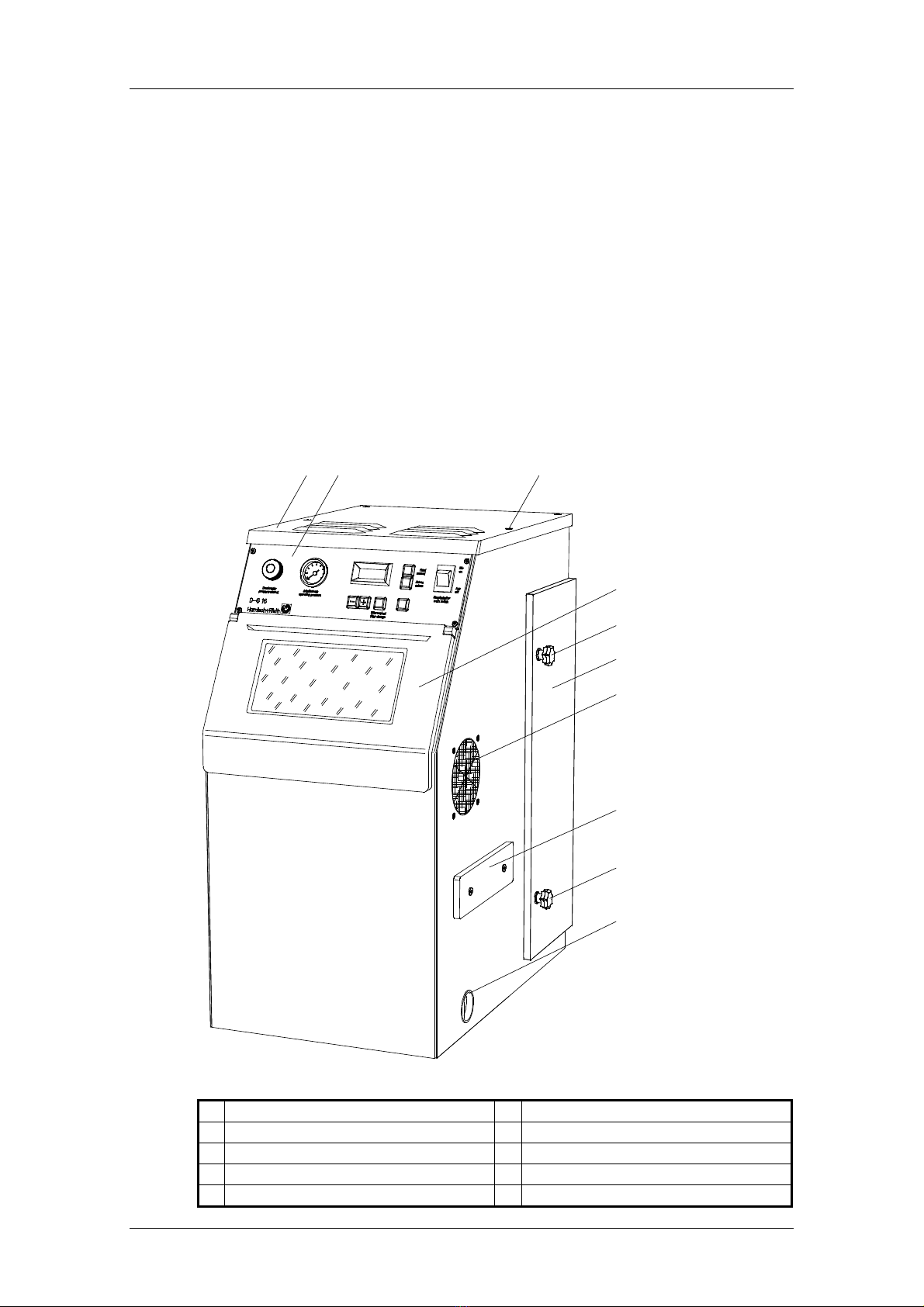
Fig. 1: View from the right and the front
1
Device lid 6
Door for filter area
2
Shield 7
Hand through-grip(only on the right side)
3
4 x hexagon socket screws 8
Slide-in sieve
4
Front lid 9
Sand drain lid
5
Star handle
D-G 16 S2 - 18.04.13 / Vers.: 1
5
17
16
15
14
4
13
3 1 10
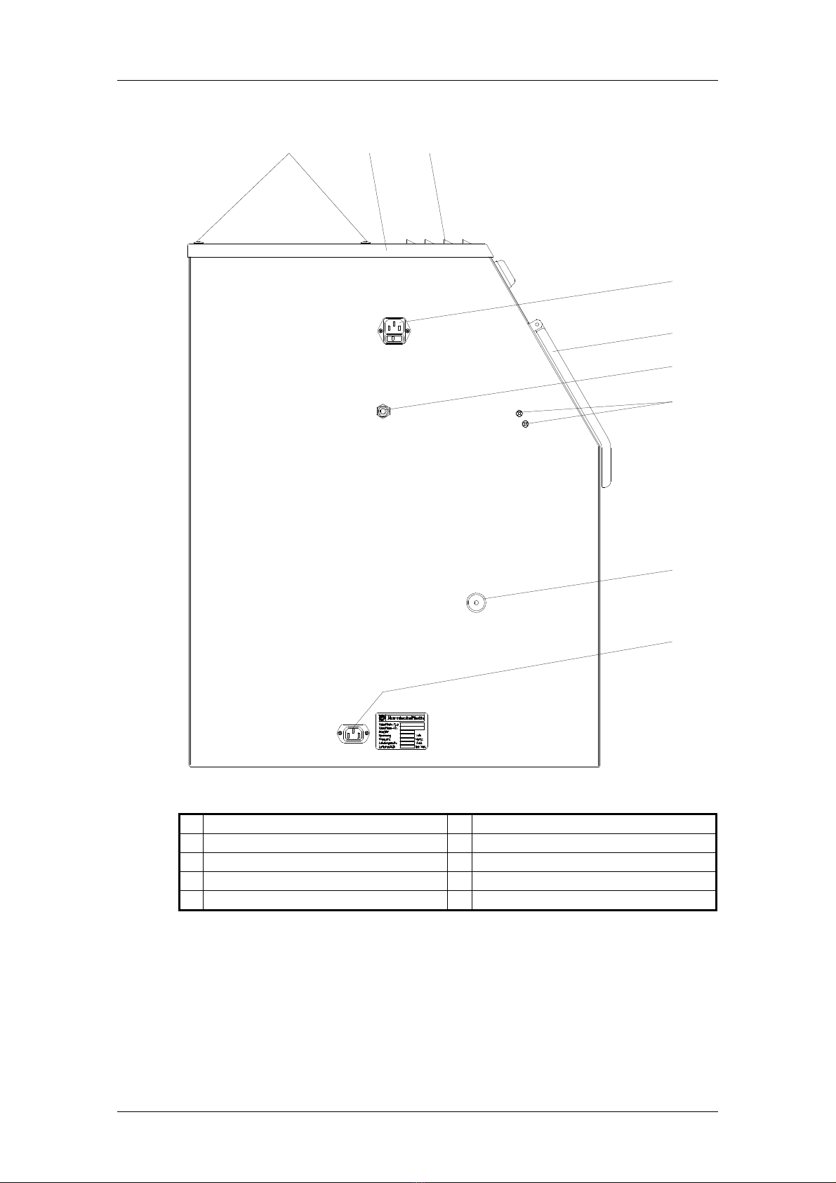
Fig. 2: View from the left
1
Device lid 14
Compressed-air connector
3
4 x M5 hexagonal socket screws 15
Screws for injector mounting
4
Front lid 16
Knurled nut for slide-in sieve
10
Air outlet 17
Socket for foot switches
13
Mains socket (230 V /50 Hz)

6
D-G 16 S2 - 18.04.13 / Vers.: 1
45
42
48
41
31
8
64
63
19
62
27
26
4
10 46 3 29 40 30 47 3
61
50
33
34
18 49
43
1
20
70
28
75
Fig. 3: Device sectioned through the middle and viewed from the right
1
Device lid 40
Support Ø 63 mm
3
4 x M5 hexagonal socket screws 41
Plastic connector for the filter bag
4
Front lid 42
Cover plate for filter bags
8
Slide-in sieve 43
2 x knurled nuts
10
Air outlet 45
Filter bag
18
Sandblasting area light (230V) 46
Aspirator motor
19
Injector mounting 47
Aspiration area
20
Injector 48
Mesh basket
26
Abrasive aspirator hose 49
Sealing surfaces
27
Air hose on the injector (20) 50
Filter area
28
Air hose on the injector (70) 61
Drive motor for sandblasting cage
29
Fine particle filter 62
Fastening binder (securing for transportation)
30
Fine particle filter bracket 63
Rounded head screw
31
Sand aspirator basket 64
Sandblasting cage
33
Middle floor area 70
Injector for manual blasting
34
4 x screws for floor area 75
Orientation pin
D-G 16 S2 - 18.04.13 / Vers.: 1
7
2.4 Process for putting into operation
(see fig. 2 page 5)
1. Connect unit to compressed air supply (see section “3.1”).
2. Fill blasting agent (see section “3.2”).
3. Check filter system (see section “3.3“).
4. Connect pedal switch to plug socket (1) (in blasting chamber during transportation)
5. Insert mains connection plug (in blasting chamber during transportation) in plug socket (15) and
establish connection to mains supply (230 V/50 Hz).
6. Automatic operating mode (see section “3.4”).
7. Manual blasting (see section “3.6”).
3 Operation
3.1 Connect sandblasting device to the compressed air supply
(see fig. 2 page 5)
1. Connect fabric hose included in delivery to compressed air connection (16).
2. Connect plug-in socket for rapid action coupling with compressed air supply (max. 10 bar).
Caution
Only compressed air free of moisture and oil should be used.
A water separator should be installed directly prior to, or at a max. of 1 m distant from,
the unit
to ensure fault-free operation.
3.2 Filling with blasting agent
(see diag. 1 & 2 page 4 & 5)
The unit is designed by the manufacturer to be used with the following blasting agents:
Type of blasting agent Blasting agent category
Special fused alumina (aluminium oxide) EW 60 (250 µm)
EW 80 (180 µm)
Cat. 60 B (120 µm)
Polishing blasting agent Cat. 150 A (150 µm)
Caution
The unit is designed for use with Harnisch+Rieth blasting agents. Harnisch+Rieth are not liable
for any malfunction or damage resulting from the use of other blasting agents.
1. Open front flap (2)
Note Unscrew knurled nut for shove-in sieve (10) and pull out shove-in sieve (8) to about
3
/
4
of its
length to facilitate inspection of the blasting agent filling level.
2. Fill blasting agent to about 4 cm under the height of the shove-in sieve (8).
Caution
It should be ensured that there are no dirt particles in the blasting agent to avoid malfunctions.
3. Shove in sieve (8) and tighten knurled nut(10) lightly.
8
D-G 16 S2 - 18.04.13 / Vers.: 1
3.3 Fill abrasives
(see fig. 1 and 3, page 4 & 6)
Caution
The D-G 16 S2 automatic blasting unit should only be used with a correctly installed and un-
damaged super-fine filter (7) and filter bag (14).
1. Open door to filter chamber (4) by unscrewing the two star grips (11).
2. Ensure that the super-fine filter (7) is not damaged and correctly pressed onto the sealing sur-
face (49) (i.e., sealed). The two knurled nuts (43) must be tightened firmly and evenly.
3. Ensure that the filter bag (14) is inserted in an undamaged condition in the mesh basket (48).
4. The filter bag plastic connection (41) should sit securely on the connection piece (40).
5. Seal the door to the filter chamber (4) again by gently but firmly tightening the two star grips.
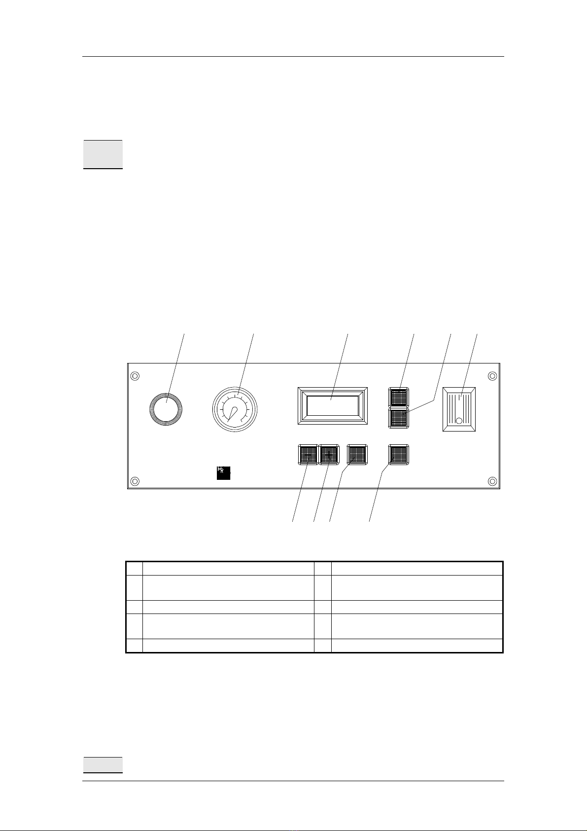
3.4 Automatic operational mode
(see diag. 1 & 3 page 4 & 6)
Aus
off
Autom.
autom.
Hand
manual
start / stop
Ein
on
Arbeitsdruck
operating pressure
D - G 16
Druckregler
pressure control
timer
sec
Harnisch+Rieth Filterwechsel
filter change
60
5
7
5
4
5
3
5
6
5251
0015
55 59 58
Fig. 4: Shield
51
Regulator for operating pressure 56
Filter change LED (red)
52
Pressure gauge for operating pressure 57
"start/stop" button (for automatic opera-
tion)
53
“-" timer pushbutton 58
"Autom./autom." button
54
"+" timer pushbutton 59
"Hand/manual" button (for manual opera-
tion)
55
Display 60
Main power switch
1. Place objects to be blasted in the sandblasting cage (64).
2. The injector (20) must be in the mounting (19) and the rounded head screw (63) must be in its
nut.
3. Close front lid (4).
4. Do not adjust operating pressure at the pressure controller (51) to more than 5bar ! The oper-
ating pressure can be checked at the pressure gauge (52).
Note Upon switching on at the main power switch the device is in an operation ready state.

D-G 16 S2 - 18.04.13 / Vers.: 1
9
5. Turn on device at the main power switch (60).
-
The device is switched immediately to a manual operation mode, the "Hand/manual"
pushbutton lights up green.
6. Press "Autom." pushbutton (58), it lights up green.
7. Set sandblasting time using the pushbuttons "+" and ” -".
Note The sandblasting time set with pushbuttons "+" and “-" is stored automatically after 2 seconds.
The stored sandblasting time also r
emains in effect if the device is switched off or there is a
power failure.
8. Press "start/stop" (57) button
-
Aspiration starts,
-
Sandblasting area light is activated,
-
Sandblasting cage (64) swivels,
-
Injector (20) blasts.
9. After expiry of the set sandblasting time the aspiration is stopped after approx. 7 seconds and
the sandblasting area light is turned off after approx. 20 seconds.
Note
During blasting, blasting can be deactivated using the "start/stop" pushbutton, with the blasting
time being preserved in
the display. By pressing the "start/stop" pushbutton again the blasting
process is reinitiated and the blasting time continues running in the display.
Note During automatic operation it is also possible to blast manually using injector (70) by activat
ing
the foot switch.
3.5 Description of how to set and save the blasting time
-
the maximal adjustable blasting time is 60 minutes
-
the minimum adjustable blasting time is 1 minute
-
the blasting time can be adjusted in 1 minute steps
-
by pressing the "+" and “-"pushbuttons, the blasting time is reset and stored after approx. 2 sec-
onds.
Note
If the blasting time is reset during blasting, this blasting time is then stored in the memory. Upon
restarting the device the last time set is indicated on the display.
3.6 Manual blasting
(see fig. 1 and 4, page 4 & 8)
1. Close front lid (4) and turn on device at the main power switch (60).
-
The internal light (18) is switched on,
-
Aspiration is set in motion,
-
The pushbutton "Hand/manual" (59) illuminates.
2. Do not adjust operating pressure at the pressure regulator (51) to more than 5 bar! The operat-
ing pressure can be checked at the pressure gauge (52).
3. The sand blast (from the injector (70) for manual blasting) is released by activating the foot
switch.

10
D-G 16 S2 - 18.04.13 / Vers.: 1
3.7 Automatic cut-out and filter change warning light
(see fig. 1 and 4, page 4 & 8)
Note
As soon as the max. permissible filling of the filter bag (45) is reached, the automatic cut out is
activated via an underpressure sensor and the red warning light "Filter wechseln" (56) lights up.
Blasting is interrupted with the aspiration continuing for about 7 seconds.
-
The filter bag (45) must be changed, see section “4.1”.
Note If the device is deactivated by the automatic cut out, further work can be carried out
for a short
time by turning on and off again and tapping the filter bag (45) without any need to exchange it.
-
For tapping the filter bag (45), open the door for the filter area (6)
Note If after automatic cut-out (filter change display lights up) the
filter bag (14) is only partially filled,
the fine particle filter (29) must be checked and if necessary cleaned, see section “4.2”.
4 Cleaning/maintenance
(see fig. 1 and 4 , page 4 & 8)
Note If the unit is switched off by the automatic switch-
off it is possible to work for some time without
replacing the filter bag by turning the unit off and on again and tapping the filter bag (14).
Open the filter chamber door (4) to tap the filter bag (14).
4.1 Replacing the filter bag
(see diag. 1 & 3 page 4 & 6)
1. Open the filter chamber door (4).
Note The super-fine filter (7) should be inspected and/or cleaned if, after the automatic switch-
off
responds (the filter change indicator illuminates), the filter bag is only slightly filled.
(See section “4.2”)
2. Press the plastic connection (41) away from the connection piece (40) with both hands.
3. Close filter bag (14) with attached plastic cover (42).
4. Carry the filter bag (14) in the mesh basket (48) to the disposal point.
5. Insert new filter bag (14), sealed tightly, and inspect filter installation. (See section “3.3”).
Note
The disposable filter bag should under no circumstances be emptied and reused, as this can
lead to malfunctions, not to mention the fact that this can be detrimental to health.
4.2 Cleaning (replacing) the super-fine filter
(see diag. 1 & 3 page 4 & 6)
Note The super-fine filter (7) should also be removed and dry-
cleaned or replaced after the filter bag
(14) has been changed about ten times! We will gladly take care of the cleaning of your super-
fine filter (7) on an exchange basis. We would be only too pleased to exchange your fine-
particle filters in order to clean them, whereby only type-checked filters compliant with du
st
class M (DIN 60335) are employed.
1. Open door to filter chamber (4) by unscrewing the two star grips (11).
2. Press the plastic connection (41) away from the connection piece (40) with both hands.

D-G 16 S2 - 18.04.13 / Vers.: 1
11
3. Remove filter bag with mesh basket (48).
Danger
Switch off unit at main switch (12)! Pull out mains supply plug!
4. Unscrew 4x hexagonal socket screws (60) and remove cover (66).
5. Unscrew 2x knurled screws (43) in filter chamber (51) and remove the strip (17) upwards.
6. Remove super-fine filter (7) upwards.
Caution
There should be no dust lying on the sealing surfaces (49) or in the suction chamber (47), as
dust could possibly damage the extraction motor (46). The filter chamber (51), suction chamber
(47) and sealing surfaces (49) should be suction cleaned.
7. Insert cleaned or new super-fine filter (7).
8. Insert strip (17) from above.
9. Tighten the 2x knurled screws (43) firmly and evenly again.
10. Replace cover (66) and tighten with 4x hexagonal socket screws (60).
11. Shove in the mesh basket (48) together with the inserted filter bag (14) and press the plastic
connection (41) onto the connecting piece (40) with both hands.
12. Inspect filter installation. (See section “3.3”).
4.3 Cleaning the shove-in sieve (embedded material residue)
(see diag. 1 & 2 page 4 & 5)
1. Unscrew knurled nuts for shove-in sieve (10).
2. Pull out shove-in sieve (8) and clean.
3. Firmly tighten the knurled nuts manually after inserting the shove-in sieve.
4.4 Draining of the abrasive
(see diag. 1 page 4)
1. Position unit with sand drainage outlet on table edge.
2. Drain blasting agent by removing plastic sand outlet cover (13).
Note On this occasion, the shove-in sieve (8) should also be removed and cleaned.
(See section “4.3”)
12
D-G 16 S2 - 18.04.13 / Vers.: 1
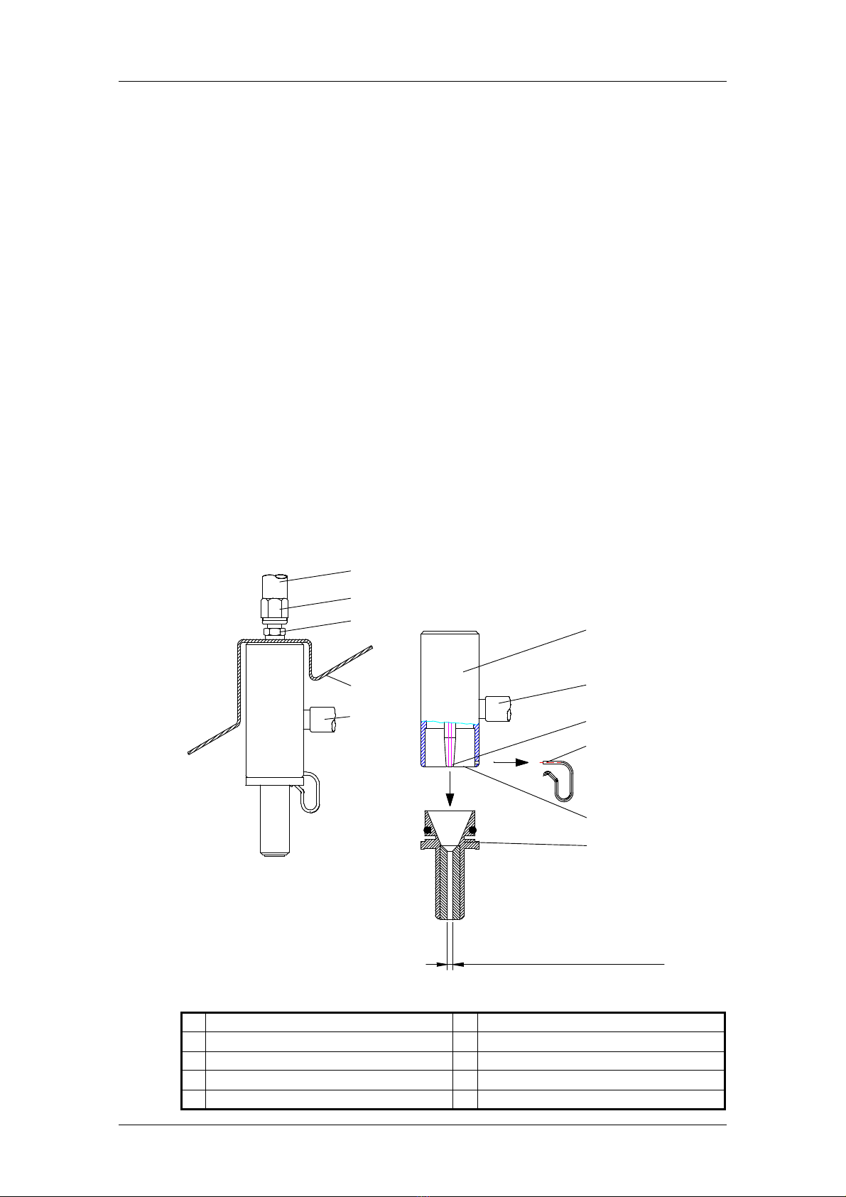
4.5 Checking of the injector if blasting performance is reduced
(see fig. 3 and 4, page 6 & 8)
If there is reduced blasting performance, the injector (20), the jet nozzle (22) and the aspirator
basket (31) must be checked as follows:
1. Disconnect device at the main power switch (60) ! Pull out power plug!
2. Hang up injector (20) after releasing the screw (63) and unscrew injector (70) from its mounting.
3. Pull clip connectors (21) to the side.
4. Pull jet nozzle (22) out by turning and while holding the injector housing (20).
5. Check whether any foreign bodies are present in the nozzle holes, and remove these wherever
appropriate.
6. A severely blasted out nozzle (22) (diameter greater than 4.5 mm) must be replaced.
7. The injector pin (23) must be flush with the surrounding injector ring (24). If the injector pin is
shortened by more than 1.5 mm due to wear, the injector must be replaced.
8. Check the injector pin for any possible external damage.
-
Close off air hoses (27) and (28) and remove injector along with abrasive aspirating hose
(26).
9. Check the aspirator basket (31) in the lower part of the sand reservoir for contamination, and if
necessary clean it. For this purpose see “Draining of the abrasive” section “4.4”.
22
26
24
21
23
70
72
26
29
71
28
Diameter greater than
4.5 mm = exhange jet nozzle
Fig. 5: Dismantling of the injector (70) for manual blasting
21
Clip connector 28
Air hose for injector (70)
22
Jet nozzle 29
Sandblasting area shield
23
Injector pin 70
Injector for manual blasting
24
Injector ring 71
Coupling nut
26
Abrasive aspiration hose 72
Hose fitting

D-G 16 S2 - 18.04.13 / Vers.: 1
13
22
26
24
21
23
20
27
2
7
2
6
2
0
28
19
62
63
Diameter greater than
4.5 mm=exchangejet nozzle
Fig. 6: Dismantling of the injector (20) for automatic blasting
19
Injector mounting 24
Injector ring
20
Injector housing 26
Abrasive aspiration hose
21
Clip connector 27
Air hose
22
Jet nozzle 28
Arrow (Direction for dismantling the injec-
tor)
23
Injector pin 63
Rounded head screw
Caution
If the injector (20) is remounted for automatic blasting the injector must be aligned together with
the jet nozzle using the orientation pin (75) Correction of the orientation of the nozzle is carried
out at the two screws (15). See fig. 2 page 5 and fig. 6 page 13.
Jet nozzle
Injector
Sandblasting
cage
Backwall off
sandblastingarea
Sidewall of housing
Rubberplate
=
=
10
20 mm
Orientationpin
Ø3x163mmlong
Thejet nozzleandthe
orientationpinmustpoint
inthisdirecktion
Thecagesidewalls
must beparallel tothe
housing
Fig. 7: Orientation of the jet nozzle

14
D-G 16 S2 - 18.04.13 / Vers.: 1
4.6 Checking of other components
In order to prevent premature wear and any damage resulting from that, all components ex-
posed to abrasive must be checked at regular intervals. The sandblasting cage as well as its
rubber attachments should receive special attention when checking for wear and be exchanged
wherever appropriate.
5 Sandblasting area illumination
(see fig. 3 page 6)
The blasting chamber illumination (18) requires 230 V/50 Hz.
A defective incandescent lamp is replaced as follows:
1. Switch off unit at main switch (12)! Pull out mains supply plug!
2. Unscrew lamp protection glass (18).
3. Unscrew incandescent lamp.
4. Screw in new E 14 230V / 40 watt incandescent lamp.
5. Screw on lamp protection glass (18) again.
6 Electrical fuse protection
(see diag. 2 page 5)
Two main fuses (5 A/T) are integrated in the mains supply connection socket (13)
7 Access to electrical/pneumatic control system
(see diag. 1 & 2 page 4 & 5)
Danger
Switch off the main switch (12) and pull out the mains supply plug before accessing the electri-
cal/pneumatic control system.
The electrical/pneumatic control system is located under the unit cover (66).
The unit cover is removed by unscrewing the 4x hexagonal socket screws (60).

8 Warranty conditions
This device conforms with current safety regulations and was subjected to extensive testing be-
fore leaving the works.
We grant a 12 months guarantee in which we are obliged to carry out all repairs necessary as a
result of material or production faults free of charge.
Warranty limitations:
1. The guarantee is considered void if repairs are not carried out by specialized dealers or by us.
2. Spare parts deliveries made for reasons covered by the guarantee do not lead to an extension
of the original guaranty period.
3. Incorrect installation (e.g. failure to heed VDE* regulations or written installation instructions).
4. Incorrect operation or stress.
5. External influences (e.g. transportation damage, damage caused by impacting or blows, dam-
age caused by the effects of weather or other natural phenomenae).
6. Repairs and alterations not carried out by authorized third parties.
7. Unit breakdown resulting from adjustment, alteration or any other attempt to adapt the unit is not
considered a material or production fault. This guarantee neither encompasses the costs of
such adjustment, alteration or any other attempt to adapt the unit, nor remedying of the
resulting damage.
8. Normal wear and tear (e.g. spray nozzles, hoses, and including hand-held pieces, union nuts,
glass panes, carbon brushes, illumination agents) or damage resulting from incorrect operation
is not covered by the terms of guarantee.
In order to provide you with a comprehensive service we would like you to fill out the guarantee
return form (enclosed at the beginning of these instructions) and send it to us by fax or letter
(window envelope).
* Verband Deutscher Elektrotechniker (German Electrical Technician Association)
Fax no.: 0 71 81/ 73 13 9
Machine
designation:
Automatic blasting unit
Maschine type:
D-G 16 S2
Maschine no.:
Date of purchase:
Dealer/Store:
From:
Date/signature:
--- ------------------------- ------------------------- --------------------------------------------------- -------------- für Fensterumschlag hier falten-------------- --
Duplicate
Guarantee return form
Harnisch+Rieth GmbH & Co.
Maschinenbau
Postfach 1260
73644 Winterbach

9 EC declaration of conformity
In the meaning of the EC Machine Directive 2006/42/EG
We hereby declare that the design of the machine specified below conforms with basic safety
and health requirements of the listed EC directives.
This certificate is no longer valid in the event of modifications being made to the machine which
are not approved by us.
Name of the manufacturer :Harnisch+Rieth
Address of the manufacturer :Küferstraße 14-16, 73650 Winterbach
Machine designation :Automatic blasting unit
Machine type :D-G 16 S2
The following pertinent EC directives were applied:
EC Machine Directive 2006/42/EG (29.12.2009)
EC Machine Directive 2006/95/EG (29.12.2007)
EMV Directive 2004/108/EC (20.07.2007)
The following harmonizing standards were applied:
T
h
e
following national technical specifications were applied:
DIN EN 60335
: Device for collecting dust which poses a health risk and reintroducing fresh
air into workrooms.
Technical documentation is available.
The operation instructions relating to the machine are also available.
Director of the Quality Control Department
Winterbach, 4 January 2010
DIN EN ISO 12100
Safety of Machinery—Part 1, General Principles of Design (04.2004)
DIN EN ISO 14121-1
Safety of Machinery – Principles of Risk Assessment (12.2007)
DIN EN 61,010-1
Safety regulations for measuring, control, regulating, and laboratory devices
DIN EN 60204-1
Safety of machinery - Electrical equipment of machines (06.2007)
DIN EN 61326-1
Electrical equipment for measurement, control and laboratory use –
EMV Requirements
DIN EN 61000-6-3
Radio-Suppression of Electrical Equipment –
Radio Interference Voltage / Radio Interference
Power (09.2007)
DIN EN 55 014-2
Electromagnetic Compatibility Noise Immunity, ESD, / Burst, / Surge
(10.1997).
Table of contents
Other Harnisch+Rieth Power Tools manuals


