Harper ATM 72 LC T4F User manual

ATM 72 LC
5
6
1-2024
OPERATOR’S
MANUAL
R
ATM 72 LC T4F
Serial Number: 19A01+
Part # 301017

ATM 72 LC

ATM 72 LC
1
Thank you for purchasing a Harper ATM 72.
TO THE OWNER OR OPERATOR:
Please take time to read this manual carefully before operating the ATM 72. Each operator should
be familiar with all safety precautions along with the operating and service procedures. Knowledge
and familiarity will make a difference in how the machine performs.
As with all Harper products, the ATM 72 was developed through tough design and testing proce-
dures to produce a sturdy, dependable machine. This manual gives assembly and operating infor-
mation. Read and understand all instructional materials included with the unit and its components
before operating or maintaining the equipment.
An All-Terrain Mower can present hazards to an operator who follows unsafe procedures in either
the operation or maintenance of the unit. Therefore, SAFETY WARNINGS are present at certain
locations in the text.
SYMBOL: SAFETY WARNING!
MEANING: Failure to understand and obey this warning may result in injury to you or others.
Whenever this symbol is used, please pay very close attention to the information presented, and
make sure you fully understand. If you do not, contact your dealer or Harper Industries for clarifica-
tion.
SAFETY WARNING!
All shields and guards must be in place for proper and safe operation of this equipment.
Where they are shown removed in this manual, it is for purposes of illustration and instruc-
tion only. Do not operate this equipment unless all shields and guards are in place.
© 2022 Harper Industries, Inc.
The Harper and DewEze names and the ATM logo are registered trademarks of Harper Industries, Inc. All other brand and product
names are trademarks or registered trademarks of their respective companies.
WARNING: Breathing diesel engine exhaust exposes you to chemicals known to
the State of California to cause cancer and birth defects or other reproductive harm.
• Always start and operate the engine in a well-ventilated area.
• If in an enclosed area, vent the exhaust to the outside.
• Do not modify or tamper with the exhaust system.
• Do not idle the engine except as necessary.
For more information go to www.P65warnings.ca.gov/diesel

ATM 72 LC
LIMITED WARRANTY
Harper Industries, Inc. (HII) warrants to each purchaser of a new Harper ATM from an
authorized dealer or representative, that such equipment is free of manufacturer’s defects
in workmanship and materials which appear while in normal service for a period of ONE
YEAR commencing with delivery to the original user.
The obligation of HII under this warranty is expressly limited, at our option, to replacement
or repair at a service facility designated by Harper Industries or at the manufacturing plant
in Harper, KS. A part will be replaced after inspection discloses it to have been defective.
This warranty does not apply to defects caused by damage or unreasonable use (includ-
ing failure to provide reasonable and necessary maintenance, or by performing functions
without genuine Harper ATM accessories) while in the possession of the consumer.
Warranty is limited to parts, labor and ground freight delivery of replacement parts. HII
shall not be liable for the consequential damages of any kind, including but not limited to
consequential labor costs or transportation charges in connection with replacement or
repair of defective parts.
This warranty does not apply to parts subjected to misuse, abuse, alteration, improper or
inadequate maintenance, or normal wear (including blades, filters, and battery).
Engines are not covered under this warranty. Refer to manufacturer’s warranty for specific
warranty information. Harper Industries, its agents or representatives, make or imply no
other warranties.
Harper Industries makes no warranty with respect to trade accessories. They are subject
to the warranties of their respective manufacturers.
ANY IMPLIED OR STATUTORY WARRANTIES, INCLUDING ANY WARRANTY OR
MERCHANTABILITY OR FITNESS FOR A PARTICULAR PURPOSE, ARE EXPRESSLY
LIMITED TO THE DURATION OF THIS WRITTEN WARRANTY. HII makes no other ex-
press warranty, nor is anyone authorized to make any on behalf of HII.
For further information please contact your nearest Harper ATM dealer.
RECORDS
Date of Purchase ______ / ______ / ______
Dealer’s Name _________________________________
Dealer’s Phone _________________________________
Serial Number Machine __________________________
Serial Number Engine ___________________________
2

ATM 72 LC
3
Table of Contents
OPERATOR SECTION
To the Owner or Operator.................................................
Warranty Statement..........................................................
Table of Contents..............................................................
Introduction.......................................................................
Specifications....................................................................
Control Identification.........................................................
Throttle...............................................................
Mower Switch.....................................................
Deck Lift.............................................................
Lights..................................................................
Ignition................................................................
Park Brake.........................................................
Manual Override.................................................
Deck Wing Raise/Lower.....................................
Manual Leveling.................................................
Inclinometer Switch............................................
Safety Guidelines
Equipment & Controls........................................
Safety Decals.....................................................
Diesel Fuel.........................................................
Guards & Shields...............................................
Battery................................................................
Hydraulics..........................................................
Safety Interlocks/Wiring Logic............................
Before Operation................................................
During Operation................................................
Maintenance
Hydraulic System...............................................
Grease Zerk Locations.......................................
Air Cleaner.........................................................
Cooling System..................................................
Engine Oil..........................................................
Fuel Filter...........................................................
Fuse/Relay Panel...............................................
Deck Service Mode...........................................
Tow Procedure/Transporting
Moving the machine w/o starting.......................
Park Brake Release...........................................
Opening the Bypass Valve.................................
Tie Down Locations............................................
Adjustments
Seat Adjustment.................................................
Deck Lift Adjustment..........................................
Cutting Height....................................................
Leveling..............................................................
Standard Torque Chart.....................................................
Service Parts....................................................................
Service Schedule..............................................................
Operating Guide...............................................................
The objective of Harper Industries in design-
ing the ATM 72 LC was to create a mowing
machine that could function safely and com-
fortably on slopes and inclines. The result is
an All-Terrain Mower that will automatically
adjust itself to keep the operator in a vertical
position on all slopes up to 34 degrees.
Driving with an automatic leveling device will
be a new and different experience. After
several minutes of driving, the smooth control
and sturdy feel will become comfortable to
you. The security of always sitting upright and
the feel of powerful, positive traction will give
you confidence and comfort in most mowing
situations.
However, we urge EXTREME CAUTION or
else your confidence in these features get
you into trouble.
REMEMBER: The features of the ATM 72
cannot replace good common sense.
1
2
3
4
5
6
6
6
6
6
6
6
6
6
6
6
7
7
7
7
8
8
8
8
9
9
10
10
11
11
12
12
12
13
13
13
14
14
15
15
15
16
16
17
19
Introduction

ATM 72 LC
Specifications
4
Power Diesel - Kubota V1505-E4B 24.8 HP @ 2300 RPM
Main Frame Welded and formed steel frame
Decks • 2 - 36” decks (72” total cutting width)
• Independently free floating, with rear discharge
• Constructed of reinforced 10 gauge steel
Cutting Height 3 - 6” adjustable cutting height
Hydraulics • Direct hydraulic blade drive (no belts or gear boxes)
• Poclain hydrostat - PM10 variable displacement axial piston pump
• Poclain high efficiency axial piston wheel motors with integrated parking
brake.
• Hydraulic filter - 3 micron with indicator
• Hydraulic oil cooler
Speed • 0-7 MPH ground speed
• Foot operated speed control - self-centering to neutral
Options • Incline Meter Assembly - Part # 815052
• Factory Install Wheel Weight Kit - Part # 801005
• Customer Install Wheel Weight Kit - Part # 801004
• White Canopy - Part # 802039
• Red Canopy - Part # 802040
Tires Drive Tire: 25” x 11-12 - 6 ply
Stabilizer Tire: 16.5” x 6.5 x 8” foam filled
Deck Caster Tire: 11” x 4.00 x 5” foam filled
Steering Power steering with automotive type steering wheel
Seat Adjustable ride suspension, arm rests, and retractable seat belt
Electrical 12 volt, 40 Amp Electrical System
Dimensions Length – 107 in., Height – 90 in., Width – 74.5 in.
Weight 2480 lbs.
Liquid Capacities Fuel – 10 Gallon; Hydraulic Fluid – 11.5 Gallon
Safety & Hydraulic
Oil
•Includes Certified ROPS with hazard lights (meets ANSI/OPEI B71.4 standards)
•Seat belt
•Crown AW46; ISO 46 Hydraulic Oil
NOTE: Following publication of this manual, certain changes in standard equipment and/or options
may have occurred which would not be included in these pages. Your Harper dealer is the
best source for up-to-date information.

ATM 72 LC
5
Control Identification
Roll Over
Bar
Wheel
Motor
Caster
Wheel Stabilizer
Wheel
Supporting
Arm
Stabilizer
Arm
Equalizer
Arm
Stabilizer
Wheel
Control
Panel
Caster
Wheel
Cutting
Deck
Deck
Motor
Leveling
Cylinders
Inclinometer
Module
Hydraulic
Reservoir
Outside
Deck Height
Adjustment
Deck Lift
Cylinder
CowlingHood
Diesel Fuel Tank
(located under hood
at front of mower)
Tow Valve & Neutral
Safety Switch
(located behind
cowling and above
propulsion pump)
ATM 72 LC
6
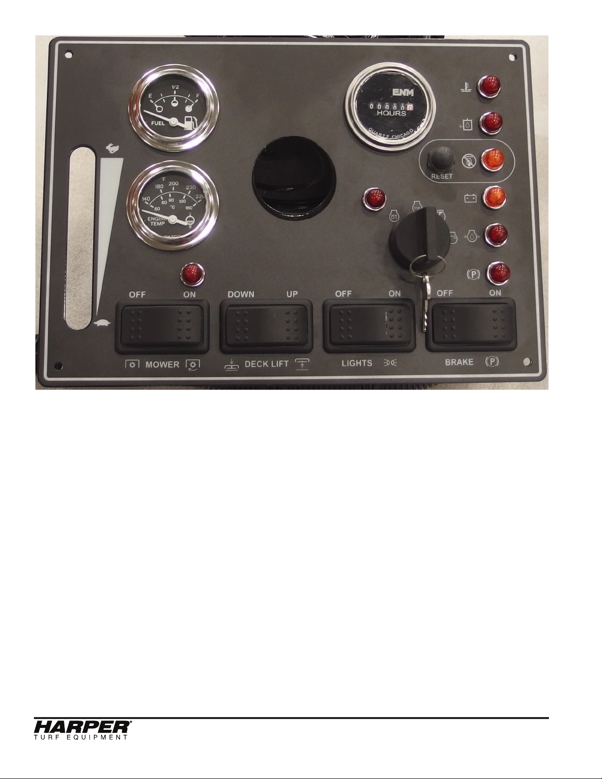
Throttle – adjust engine speed with throttle.
Start at low throttle, allow engine to warm up,
then operate unit at full throttle.
Mower Switch – turns the deck blades on
and off allowing user to cut the grass.
Deck Lift Switch – raises and lowers the
mower deck.
Lights Switch – turns on headlights.
Ignition – turn the key to the left until the
pre-heat light turns off. Then, turn key to right
to start unit. Remove key when unit is not in
use. Never leave unit unattended with key in
ignition.
Park Brake – set park brake when unit is not
in use or is parked on an incline. Make sure
park brake is disengaged before operation.
Momentary Reset Switch– resets the auto
level function after the machine has been
locked out. Once the machine is level, the
reset button can be pushed to turn on the
auto level function.
Mower Deck Light – is on when the mower
blades are engaged.
Engine Pre-Heat Light – turns on when the
key is in the pre-heat position.
Engine Temp Light – turns on when the en-
gine temp exceeds 215° F.
Hydraulic Level Light – turns on when the
hydraulic oil is low.
Leveling Lockout Light – turns on when the
auto level function has been locked out.
Ignition
Throttle
Engine Temp
Hydr. Level
Leveling
Lockout
Battery
Engine Oil
Parking Brake
Engine
Pre-Heat
Mower Deck
Momentary
Reset
Deck Lift Lights BrakeMower

ATM 72 LC
Battery Light – is on when the charging sys-
tem voltage is low.
Engine Oil Light – turns on when the oil
pressure drops below 7 psi.
Parking Brake Light – is on when the park
brake is applied
.
Manual Leveling Switch – one is located
on the arm rest and the other on the ROPS.
Both of these switches perform the same
function. One is intended to be used while
in the operator’s seat and the other for when
standing behind the machine. They are used
to manually tilt the machine left or right.
Auto/Manual Leveling Switch – determines
if the machine is leveled automatically using
the signal from the inclinometer module or
leveled only using the manual leveling switch.
Inclinometer Module – senses if the ma-
chine is off center/vertical. The machine can
lean to either side up to 34° before reaching
its limit.
• The inclinometer module includes a
dual axis (XY) accelerometer. It
measures the force caused by
movement of the sensor (accelera-
tion). Gravity puts a force on the
sensing elements that can be mea-
sured. The sensor is an analog device
with a voltage for X and a voltage for
Y. The module uses the voltage
outputs from the sensor to determine
the angle of the machine.
• When the inclinometer module mea-
sures an angle 4 degrees or greater
from center, it sends a +12 V signal to
the hydraulic valve to operate the
appropriate leveling cylinder to return
the machine to an upright position.
SAFETY WARNING!
Do not leave ATM 72LC unattended, or
attempt any service or inspection unless
the machine has come to a complete stop
and the engine has been shut o.
7
Manual
Leveling
Auto/Manual
Leveling
Manual
Leveling

ATM 72 LC
Equipment & Controls
•Read and understand this manual.
• Altering this equipment in any manner
which adversely affects its operation,
performance, durability, or use will void
the warranty and may cause hazard-
ous conditions.
• Know the location and function of all
controls and how to stop this equip-
ment quickly in an emergency before
you operate the equipment.
• Keep all nuts, bolts and screws tight to
help ensure safe operation of this
equipment.
• Use genuine factory parts or parts with
equivalent characteristics, including
type, strength and material. Failure to
do so may result in product malfunc-
tion and possible injury to the operator
and/or others.
• If hardware is not secure, or if some of
the hardware is over-tightened, equi-
pment failure may result, posing pos-
sible safety hazards.
• To prevent possible eye injury, always
wear SAFETY GLASSES while oper-
ating equipment.
• Always wear a respirator when work-
ing in dry/dusty conditions.
Safety Decals
• If safety related or instructional decals
become illegible or are removed, re-
place them immediately. New decals
may be obtained from your local Harp-
er Dealer.
• If you replace parts that have such
decals attached to them, make sure
the decals are replaced with current
versions, and are on the replacement
parts before the machine is operated
again.
Diesel Fuel
• Always use an approved container for
transporting diesel fuel.
• Do not allow open flames or sparks
while performing maintenance or refu-
eling.
• Never remove fuel tank cap or add
fuel when engine is running or while it
is hot.
• Only use ultra low sulfur diesel.
• Never fill fuel tank indoors. Fumes are
heavy and will sink to the lowest point,
collect and become hazardous.
• Wipe up spilled fuel immediately.
• Do not store fuel in a room with an ap-
pliance that has a gas pilot or electri-
cal switch that may cause sparks.
• Always store diesel outside in a safe-
ty can (a can with flame arrestor and
pressure relief valve in pour spout).
• Never store the equipment with fuel in
the tank inside a building where fumes
may reach an open flame or spark.
• Allow the engine to cool before storing
in any enclosure.
• Be certain to provide adequate ventila-
tion if an engine must be run indoors -
exhaust fumes are dangerous.
SAFETY WARNING!
Diesel fuel is extremely ammable and can
be highly explosive.
Guards & Shields
• Keep all safety devices in place.
• Replace all worn, damaged, unusable,
missing or lost safety shields and
guards before operating the equip-
ment.
• Keep the equipment in good operating
condition.
Safety Guidelines
8

ATM 72 LC
9
Battery
SAFETY WARNING!
Batteries can produce explosive gas.
Use extreme caution when working on
the battery.
• Ventilate when charging battery or us-
ing in an enclosed space.
• DO NOT produce sparks from cable
clamps, tools, or other sources; and
DO NOT allow flames or smoking in
the vicinity of the battery.
• Shield eyes when working near bat-
tery.
Hydraulics
SAFETY WARNING!
Escaping uid under pressure can
penetrate skin causing serious injury.
To prevent serious injury or death:
• Relieve pressure on system before
repairing, adjusting or disconnecting.
• Wear proper hand and eye protection
when searching for leaks.
• Use wood or cardboard instead of
hands when looking for leaks.
• Keep all components in good repair.
• Do not use any type of heat (welding,
soldering, cutting torch, etc) near
pressurized lines.
Safety Interlocks/Wiring Logic
• To start the machine, it must be in
neutral and the blades must be off.
• To turn the mower blades on, the
operator must be in the seat, and the
hydraulic oil temperature must be
below 190° F.
• There is a 2 second time delay added
to the seat switch to account for
bounce.
• The park break is applied when the
operator is out of the seat.
• Leveling
1. Valves on the cylinders are open
when in auto mode or when the
manual switch is activated to level the
machine.
2. If the inclinometer senses that the
machine is not stable or that the
machine has changed angle at a quick
rate, the valves on the leveling
cylinders are closed to lock the
machine in its current position. When
this happens, the leveling lockout indi-
cator light on the dash will be illumi-
nated. To reset the auto level
function, press the momentary reset
switch on the dash.
Before Operation
• Before operating this equipment, read
and understand the Owner’s Manual.
• Do not allow children to operate this
machine.
• Wear approved eye and ear protection
and other appropriate safety equip-
ment while operating the machine.
• Check tire pressure and fill to
specifications.
• Engine settings are preset and should
not be changed; any change can dam-
age moving parts and void the war-
ranty.
• Before starting the machine, visually
inspect all nuts, bolts and other fasten-
ers to see that they are properly se-
cured. Nuts, bolts and other fasteners
should be checked every 8 to 10 hours
of operation for proper alignment and
tightness.
• Replace damaged or missing safety
decals.
• Use factory authorized parts or their
equivalent.
• Make sure that all bearings or hinging
parts are greased and or oiled prop-
erly.
ATM 72 LC
During Operation
• Always keep a fire extinguisher near
the mower during operation.
• Keep clothing and all body parts away
from rotating parts.
• Keep the engine area clean from de-
bris and other accumulations to lessen
the possibility of fire.
Hydraulic System
• The hydraulic system of the ATM72LC
is filled at the factory with Crown AW
46 hydraulic oil that has an ISO of 46.
• The ATM72LC has a 3 micron, beta
rated hydraulic oil filter designed for
long life.
The following list of hydraulic fluids are com-
patible and can be mixed with Crown hydrau-
lic fluid. MIXING OTHER OILS THAT ARE
NOT INCLUDED ON THIS LIST COULD
CAUSE GELLING AND DAMAGE TO THE
HYDRAULIC COMPONENTS. If another
type of oil is desired, then the system must
be completely drained and flushed first.
Appropriate replacements:
ISO 46: Recommend for running in ambient
air temperatures of 32°F-110°F, and it con-
tains a kinematic viscosity rating around 46
cSt at 40°C. (1cSt = 1mm²/s)
• Mobil DTE 25
• Mobil DTE 15M
• Amoco Rykon Premium Oil ISO 46
• Chevron Rykon Premium Oil ISO 46
• Conoco Hydroclear AW MV 46
• Exxon Univis N 46
• Pennzoil AWX MV 46
• Shell Tellus 52 M46
• Shell Tellus 52 V46
• Texaco Rando HDZ 46
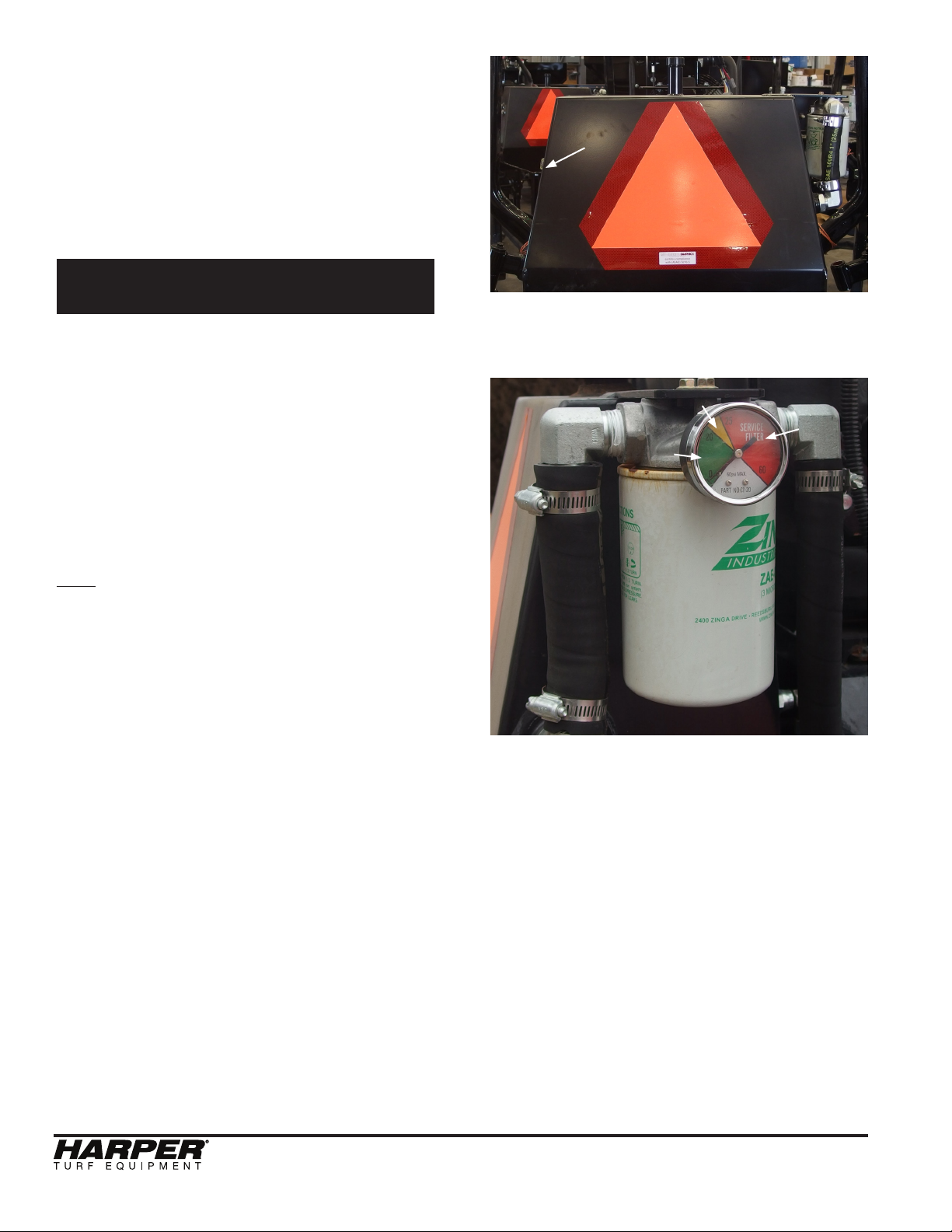
• On a daily basis, monitor the needle in
the filter indicator when the oil is at
normal operating temperature.
• The filter (part no. 822044) does
not need replaced until the needle is in
the red portion of the gauge.
• To replace filter , twist the filter
counter-clockwise. Replace with new
filter by turning it clockwise until tight.
• The hydraulic oil level should be moni-
tored daily with the hydraulic tank’s
sight glasses on the left hand side of
the hydraulic tank.
• Keep the hydraulic oil just above the
lower sight glass at all times.
• Fill reservoir through the fill location on
top of the reservoir.
Yellow
Green
Red
Filter Indicator
Hydraulic
Filter
10
Oil Filter
Hydraulic
Reservoir
Sight
Glasses
(left hand side)
Oil Fill
Maintenance

ATM 72 LC
11
Grease Zerk Locations
*
**
*
* Denotes a second grease zerk identical to this one on the other side.
(view from the bottom)
PROCEDURE
1) Park on level ground and set park
brake.
2) Turn off ATM.
3) Give 2 to 3 shots of grease after every
10 hours of use.
Air Cleaner
• Make sure intake is always free of
debris.
• When engine is turned off, remove the
wing bolt.
• Replace the air filter according to the
Maintenance Schedule.
Air Intake
Air Filter
ATM 72 LC
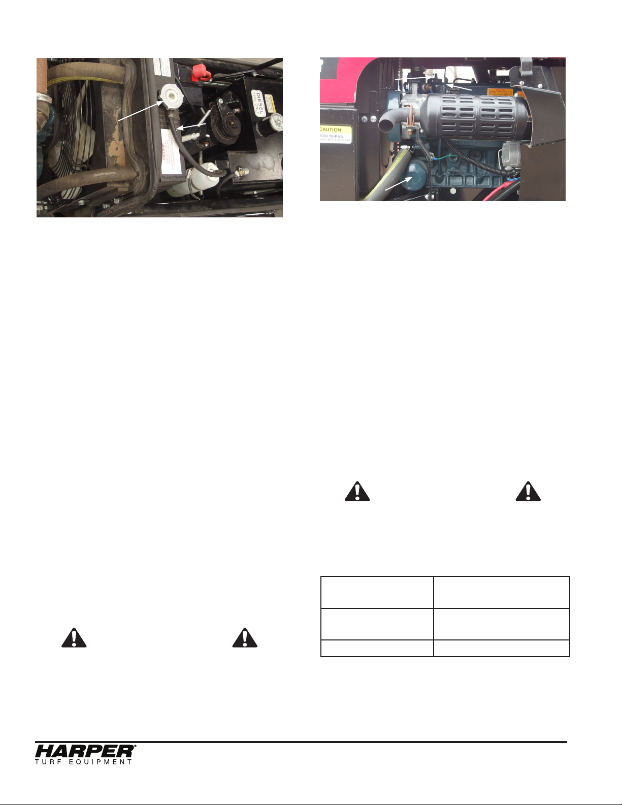
Cooling System
• The radiator and hydraulic oil cooler
are located side by side in the same
aluminum heat exchanger.
• Clear hydraulic oil cooler and radiator
of debris with pressurized air daily or
as needed.
• Check radiator level daily and only
when engine is cool and not running.
• Remove cap (radiator fill) slowly to
relieve any pressure that may be built
up.
• Fill up radiator with coolant (50% wa-
ter/ 50% antifreeze) until coolant is vis-
ible in neck of radiator.
• Make sure that the coolant recovery
bottle has at least 1” of coolant in bot-
tom. The presence of coolant in the
recovery bottle does not mean radiator
is full.
• Do NOT operate the machine if the
engine temperature exceeds 220°F.
Severe engine damage may occur if
the machine is continuously operated
above 215°F. If overheating does
occur, diagnose the cooling system
and ensuring proper coolant levels and
proper air flow across the radiator.
SAFETY WARNING
Hot Coolant and steam from the radiator
can cause severe burns. Never open the
radiator cap of a hot engine.
Engine Oil
• The dipstick and engine oil fill are lo-
cated on top of the engine.
• The engine oil filter is located on the
left side of the engine as viewed from
the operator’s seat.
• To get to the engine oil fill or dipstick,
the hood should be raised.
PROCEDURE
• Check engine oil level only when en-
gine is turned off.
• Keep engine oil level between the
FULL and ADD marks on dipstick at all
times. DO NOT OVER-FILL.
• Add engine oil (S.A.E. 10W30) through
the engine oil fill location.
• Replace the engine oil/filter according
to the Maintenance Schedule.
SAFETY WARNING
Keep dipstick and oil fill cap secured
tightly. Engine oil may escape through
these orifices when engine is running
causing severe burns.
above 25°C (77°F) SAE30 or SAE10W-30
SAE15W-40
-10°C - 25°C
(14°F - 77°F)
SAE10W-30
SAE15W-40
below -10°C (14°F) SAE10W-30
• Filled with SAE10W-30 from the
factory, 6.0 L capacity, and change
after the first 50 hours.
Engine Oil Fill
Dipstick
Engine Oil Filter
12
Radiator Fill
Coolant Recovery
Bottle
Radiator
Hydraulic
Oil Cooler
ATM 72 LC
13
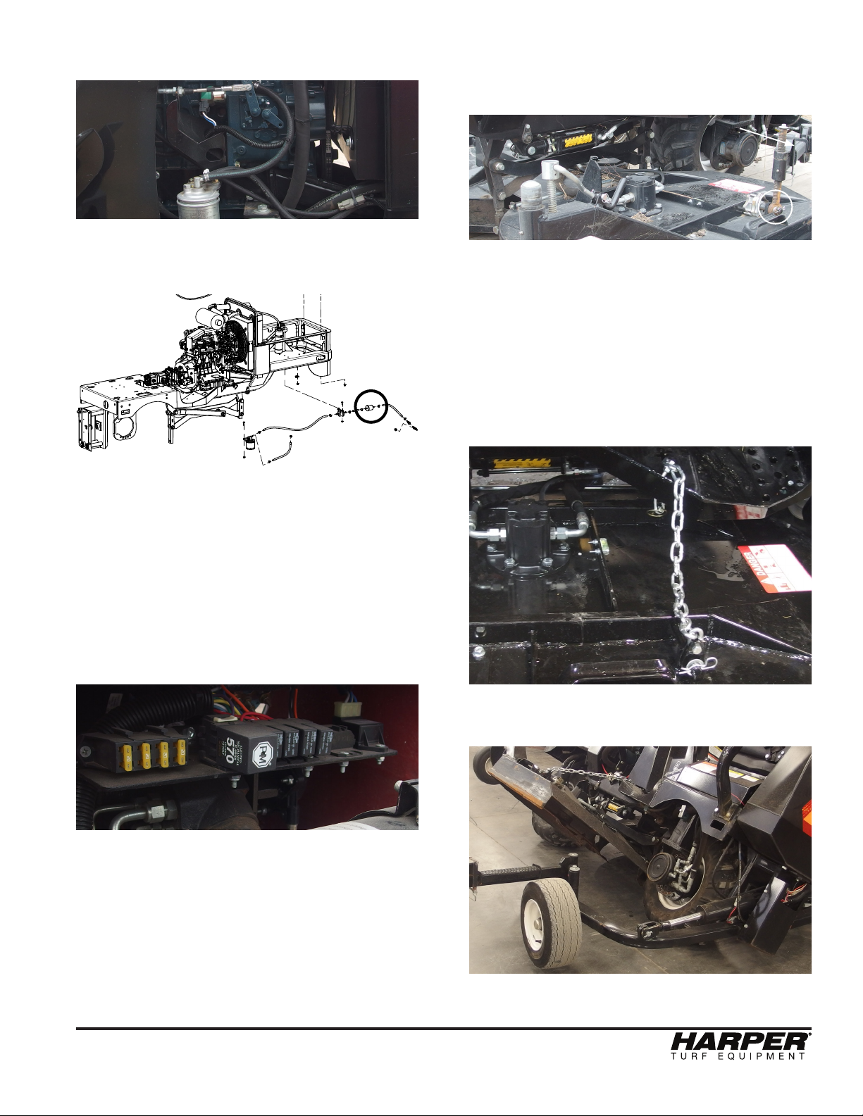
Fuel Filter
• Fuel filter is located on the right side
of the machine when viewed from the
operator’s seat.
• There is also a smaller in line fuel filter
on the bottom of the front right corner
of the machine leading from the fuel
tank to the main fuel filter.
• The Fuel Shut-off valve is located
on the lower right side of the fuel tank.
It can be accessed from below the
machine.
Fuse/Relay Panel
• Located under the hood behind the
dash of the mower.
• All fuses are 20 amp.
Deck Service Mode
• Remove hairpin cotter and flat-washer
and swing out support arm.
• Connect chain to deck and replace
pin
• With Manual Override switch, lean
mower all the way left or right. Then
insert chain into chain cutout located
on the step. Install the lynch pin in
the bottom side of the step for added
safety. After that lean the mower to
the opposite side.
• Block deck up before working under
the deck.
Fuel Filter
Pin
Support Arm
Smaller
Fuel Filter

ATM 72 LC
Hydraulic Valves
• To get to the hydraulic valves, either
remove the two rear pins holding the
seat down and rotate the seat forward
or remove all (4) pins holding the seat
down and remove the seat all together.
14
DETAIL A
SCALE 0.14 : 1
A
DECK
VALVE
AUXIALLARY
VALVE
LOOP
FLUSH
VALVE
DECK LIFT
COILS &
SOLENOID LEVELING
COILS &
SOLENOID
BRAKE
RELEASE
COIL &
SOLENOID
PRESSURE
RELIEF
COUNTER
BALANCE
VALVE
PRESSURE
RELIEF
MOWER
BLADE
COIL &
SOLENOID

ATM 72 LC
15
• After towing the unit, follow procedure
in opposite order to remove brake
release tool and install new plastic
plug.
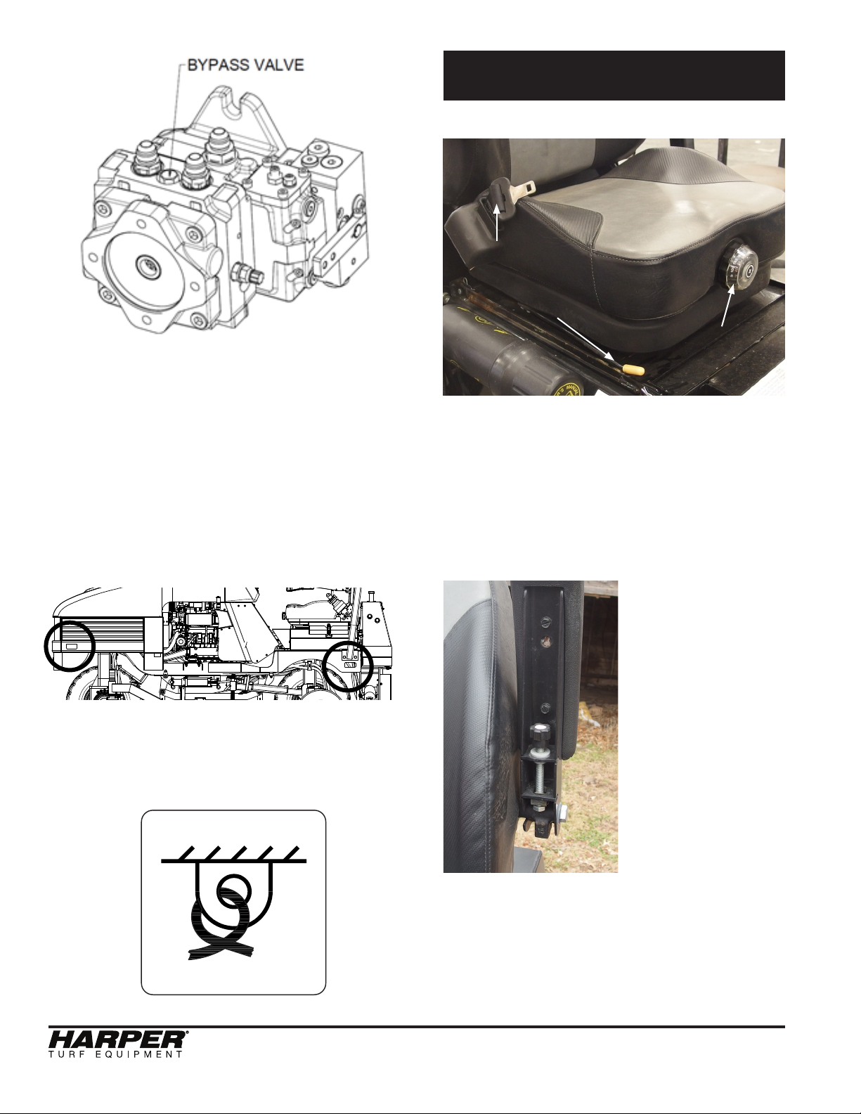
Opening the Bypass Valve
• The bypass valve is located on the
top side of the propulsion pump be-
tween the high-pressure ports. The
valve can be accessed by removing
the center cowling panel.
• Open the bypass valve when moving
the machine for short distances. The
bypass valve connects the high-pres-
sure ports A & B. Only use this valve in
an emergency case and for a short
distance.
• The bypass valve is not a tow valve and
can not be used to pull the machine for
a long distance.
PRECAUTIONS
• The bypass valve is intended only for
moving a vehicle a very short distance
and is not intended for towing a vehicle
behind a truck or tractor. Note: Serious
damage to the hydrostatic drive will
result if the vehicle is towed.
• Close the bypass valve tightly when
finished moving unit. Failure to close
valve tightly will result in full or partial
loss of power.
Moving the machine without starting the
engine
• In order to move the machine without
the engine running, the park brakes
must be released and the bypass
valve must be opened on the propul-
sion pump.
Park Brake Release
• Both of the wheel motors contain a
park brake that is mechanically applied
and hydraulically released. Whenever
the engine is off (zero system pres-
sure), the brakes are applied.
• Always release the park brakes when
towing or pushing the unit.
PRECAUTION
• Towing or pushing the unit with the
park brakes applied may cause seri-
ous damage to internal brake parts.
PROCEDURE
1. Remove plastic plug from the center of the
park brake housing.
2. Install brake release tool (P/N 575064)
by placing on brake housing and tighten-
ing the screw into the piston. These tools
can be found inside the toolbox.
3. Tighten the nut until the motor shaft turns
freely.
Tow Procedure
Wheel Motor
Plastic Plug
Park Brake
Release
(behind cover)
ATM 72 LC
Seat Adjustment
• The lever with the yellow handle
controls the chair’s forward and back
movement to allow for either more or
less leg room.
• The round knob adjusts the ride quality.
Turn the knob clock-wise for a firmer
ride, and counter-clockwise for a softer
ride.
• Adjust the
screw to change
the angle of the
arm rests.
• The seat
belt is retractable
and will lock up
on impact or
accident.
Adjustments
Seat Belt
Seat Firmness
Knob
Arm Rest
Angle Screw
Seat Front to
Back Lever
PROCEDURE
• To open the bypass valve, turn it coun-
ter-clockwise. It can be completely re-
moved from the pump housing.
However, to avoid oil leakage, only turn
the valve 2 turns.
• After the machine has been moved,
reinstall the bypass valve and reinstall
the center cowling panel.
Tie Down Locations
There are (4) tie down locations designated on
the machine that are located at the front and
rear of each side of the machine, and they are
accompanied by the following decal:
16

ATM 72 LC
17
Cutting Height
• Park the machine on level ground.
• Start the machine and raise the deck
using the switch on the dash.
• Using the decal on the side of the frame
or the picture below, identify the
cylinder spacer(s) needed to achieve
the desired cut height. The cylinder
spacers are located in the tool box on
the LH side of the seat frame. The
spacers provided include:
2 - 0.25”
1 - 0.50”
1 - 1.00”
• Install the cylinder spacer(s) onto the
deck lift cylinder (see pg. 5 for
location).
• Lower the deck all the way down using
the switch on the dash.
• The outer deck height is controlled by
the arm linkage attached to the
stabilizer arm.
• Using the crank located on the caster
wheels, raise the caster wheels so that
the deck is not supported by the caster
wheel. Turn CCW until the wheel is not
touching the ground. Repeat this step
for both sides.
• Using the outer deck screw adjustment,
adjust the deck so that it is level with
the center of the deck. A bubble level
is mounted on the deck for ease of
adjustment. Repeat for both sides.
• Lastly, adjust both caster wheels down
until they touch the ground.
X
Y
802068
1 2
0.25"
0.50"
0.75"
1.00"
1.25"
1.50"
1.75"
X
CYLINDER
SPACER
Y
CUT
HEIGHT
2.00"
3.00"
3.25"
3.50"
4.00"
4.50"
4.75"
5.00"
5.50"
6.00"
Hand Crank
Outer Deck
Adjustment
Level

ATM 72 LC
SAFETY WARNING!
Refer to the Standard Torque Chart when-
ever bolts, nuts or screws are tightened.
PRECAUTIONS
• When tightening two or more fasteners
on the same part, DO NOT tighten
the fasteners completely one at a
time. To avoid distortion, first tighten
all fasteners in sequence to one-third
of torque value, then tighten to
two-thirds of torque value, then tighten
to full value.
• All lug nuts should be torqued to
140 ft-lbs (190 N-m).
Filters
Engine Air Filter.......................
Engine Oil Filter.......................
Fuel Filter (Cannister)..............
Fuel Filter (Inline)....................
Hydraulic Oil Filter...................
Belts
Engine Fan Belt.......................
Blades
RH Swinging Blade Set...........
LH Swinging Blade Set............
Swinging Blades Bolt Kit
(1 Deck Only) ...............
RH Fixed Blade Set.................
LH Fixed Blade Set..................
Fixed Blades Bolt Kit
(1 Deck Only)................
Wheels and Tires
Stabilizer Wheel Assembly......
Caster Wheel Assembly...........
Drive Wheel.............................
Drive Tire.................................
Drive Wheel and Tire Assy.......
Standard Torque Chart Service Parts
802064
302058
302057
302103
822044
802063
500269
500268
500319
500271
500270
500320
800057
800093
842019
842020
843007
18
Table of contents
Other Harper Lawn Mower manuals


