Harris Broadcast NetWave PRE99-1600D-08 User manual
DirectView Broadcast
Console Operations &
Technical Manual
8 Channel Console with Dual Metering: PRE99-1600D-08
16 Channel Console with Dual Metering: PRE99-1600D-16
16 Channel Console with Quad Metering: PRE99-1600Q-16
24 Channel Console with Dual Metering: PRE99-1600D-24
24 Channel Console with Quad Metering: PRE99-1600Q-24
PRE75-60 Revision A – 3/13
www.harrisbroadcast.com
PR&E®NetWave™ DirectView Broadcast Console
Operations & Technical Manual
Revision A, March 2013
©Copyright 2013 Harris Broadcast. All rights
reserved.
Reproduction, adaptation, or translation without
prior written permission is prohibited, except as
allowed under the copyright laws.
Warranty
The information contained in this document is
subject to change without notice. Harris
Broadcast makes no warranty of any kind with
regard to this material, including, but not
limited to, the implied warranties of
merchantability and fitness for a particular
purpose.
Harris Broadcast shall not be liable for errors
contained herein or for incidental or
consequential damage in connection with the
furnishing, performance, or use of this material.
Trademark Credits
NetWave™, Oasis™, PR&E®, RMXdigital™,
VistaMax™, VMQuadra™, VMXpress™, and
VMConnect™ are trademarks of Harris
Broadcast. Other trademarks are the property
of their respective owners.
How to Contact Us
Harris Broadcast
Technical Service Department
3200 Wismann Lane
Quincy, IL 62305
USA
Sales: +1 217 222 8200
Service: +1 760 936 4029
E-mail: tsupport@harris.com
Web: www.harrisbroadcast.com
How to Get Support
If you have a technical question or issue with your PR&E
Studio Products equipment, please go to our customer
support web page:
http://www.harrisbroadcast.com/support/productsupport.asp
You can also call the Customer Support line or send a
non-emergency e-mail:
●U.S., Canada, and Latin America: +1-217-222-8200 or
tsupport@harris.com
●Europe, Middle East, and Africa: +44-118-967-8100 or
●Asia and Pacific Rim: +852-2776-0628 or
Revision Date Changes Made Section Pages Editor
A 3/8/2013
Updated manual for direct view meter console. Reformatted
manual and made minor grammatical and punctuation edits. All All LD
Numbered all figures and tables.
Added figures and tables to Table of Contents section. All
TOC All
iv - vi

Harris Broadcast i PR&E
Table of Contents
Declaration of Conformity............................................................... vii
Safety Instructions ........................................................................ viii
Hazard/Warning Label Identification............................................. viii
Section 1 - Introduction.................................................................1-1
Product Overview.................................................................................... 1-1
NetWave Connections......................................................................................1-2
Main Component Descriptions...........................................................................1-3
Specifications ......................................................................................... 1-9
General..........................................................................................................1-9
Dimensions ....................................................................................................1-9
Power Supplies ...............................................................................................1-9
Console Power Requirements............................................................................1-9
Required Supply Voltage & Current....................................................................1-9
Stereo Separation .........................................................................................1-10
Crosstalk Isolation.........................................................................................1-10
Frequency Response......................................................................................1-10
Dynamic Range.............................................................................................1-10
Total Harmonic Distortion + Noise...................................................................1-10
Analog Line Inputs ........................................................................................1-10
Analog Line Outputs ......................................................................................1-10
CR & Studio Monitor Outputs ..........................................................................1-10
Digital Inputs and Outputs .............................................................................1-11
Warranty ..............................................................................................1-11
Section 2 – Installation..................................................................2-1
Console Installation................................................................................. 2-2
General Wiring Info .........................................................................................2-2
Power Supply Placement ..................................................................................2-3
Grounding and Shielding..................................................................................2-3
Countertop Preparation....................................................................................2-4
Console Option Installation...............................................................................2-5
Console Display ............................................................................................2-10
Monitor & Output Board Settings.....................................................................2-13
NetWave Configuration ..................................................................................2-14
Dual Faders & DSP Cards ...............................................................................2-15
Cabling & Wiring ....................................................................................2-22
Required Cables & Wires ................................................................................2-22
Wire Preparation ...........................................................................................2-23
Crimp Tool Operation.....................................................................................2-24
Audio Connections.........................................................................................2-25
Unbalanced Connections ................................................................................2-26
NetWave Sample Rate ...................................................................................2-28
Audio Connections.........................................................................................2-28
Logic Connections .........................................................................................2-29

Harris Broadcast ii PR&E
Logic Interfaces ............................................................................................2-29
Connection Guides ........................................................................................2-34
Section 3 – Operation ....................................................................3-1
Console Parts ......................................................................................... 3-1
Dual Fader Panels ...........................................................................................3-1
Monitor Control Panel ......................................................................................3-1
Console Display ..............................................................................................3-1
Power Supply..................................................................................................3-2
VistaMax Integration and Source Selection................................................. 3-2
Quick Guides .......................................................................................... 3-2
Dual Fader Panel Quick Guide...........................................................................3-3
Dual Selector Panel Quick Guide........................................................................3-4
Dual Router Panel Quick Guide..........................................................................3-5
Monitor Control Panel Quick Guide.....................................................................3-6
Console Display Quick Guide...........................................................................3-10
NetWave Applications .............................................................................3-11
Standalone Operation ....................................................................................3-11
Telco/Codec Operation...................................................................................3-12
Section 4 - Linked NetWave Consoles ............................................4-1
NetWave Linking..................................................................................... 4-1
Operating System Version Verification ...............................................................4-2
Linked NetWave Features.................................................................................4-2
Linked NetWave Setup............................................................................. 4-3
Set Up a NetWave Console using VMCC..............................................................4-3
Edit the Device Settings...................................................................................4-5
Name and Define the Console Signals................................................................4-6
Set Up Dual Router Processor Cards ..................................................................4-7
Set Dual Router Channel Sources......................................................................4-9
Provision the Configuration Files .....................................................................4-10
Distribute the Files ........................................................................................4-11
Signal Setup Details ...............................................................................4-12
Macro Files............................................................................................4-15
Section 5 - NetWave Servicing.......................................................5-1
Parts and Repair Services......................................................................... 5-1
Parts Ordering and Repair Information...............................................................5-1
Spare and Replacement Parts ...........................................................................5-2
Installation Kits...............................................................................................5-2
Optional Upgrade Kits......................................................................................5-3
Control Panel Service............................................................................... 5-3
Control Test Mode ...........................................................................................5-3
Panel Construction ..........................................................................................5-4
Control Panel Removal and Installation..............................................................5-4
Fader Removal and Reinstallation......................................................................5-5
Console Display Service........................................................................... 5-6
Console Display Removal .................................................................................5-6

Harris Broadcast iii PR&E
Clock Troubleshooting......................................................................................5-7
Event Timer Troubleshooting ............................................................................5-7
Meter Troubleshooting .....................................................................................5-7
48-Volt Supplies ..................................................................................... 5-7
Power Supply Connections................................................................................5-7
Product Description ................................................................................. 5-8
Monitor & Output Card Status...........................................................................5-9
DSP Card Status .............................................................................................5-9
Service Setup Test Modes ........................................................................ 5-9
Section 6 – NetWave Accessories ..................................................6-1
Furniture and System Design.................................................................... 6-1
Accessory Panels..................................................................................... 6-1
Host Turret.....................................................................................................6-2
Mic Remote Control Panels ...............................................................................6-2
3x6 Headphone Distribution Amp.............................................................. 6-4
ESE/SMPTE Master Clock ......................................................................... 6-5
Quad A/D Converter................................................................................ 6-5
Dual Selector Kit..................................................................................... 6-6
Link Activation Kits.................................................................................. 6-6
Dual Router Kit....................................................................................... 6-6
NetWave Toolkit ..................................................................................... 6-6

Harris Broadcast iv PR&E
Figures
Figure 1-1. NetWave-16 Console......................................................................................................1-1
Figure 1-2. Monitor & Output Card Connections..................................................................................1-3
Figure 1-3. DSP Card Connectors and Channel Setup Controls .............................................................1-3
Figure 1-4. Dual Fader Panel............................................................................................................1-4
Figure 1-6. Dual Router Panel ..........................................................................................................1-5
Figure 1-5. Dual Selector Panel ........................................................................................................1-5
Figure 1-7. Monitor Control Panel .....................................................................................................1-6
Figure 1-8. Console Display .............................................................................................................1-7
Figure 1-9. VistaMax Link................................................................................................................1-8
Figure 2-1. Cable Access Cutout & Console Mounting Holes..................................................................2-1
Figure 2-2. Console Connections with Access Points............................................................................2-2
Figure 2-3. Technical Ground Connection Point, NetWave Chassis (right rear view).................................2-3
Figure 2-5. Use of Faders to Lift Panel...............................................................................................2-4
Figure 2-6. Red Cable on Dual Fader or Monitor Control Panel..............................................................2-5
Figure 2-7. Link Activation Kit..........................................................................................................2-5
Figure 2-8. RJ-45 Link Jack..............................................................................................................2-6
Figure 2-9. PLCC Extraction Tool ......................................................................................................................2-6
Figure 2-10. PROM U64 ..................................................................................................................2-6
Figure 2-11. VistaMax Enabled Label on Monitor Control Panel.............................................................2-7
Figure 2-12. 10-Character Display Orientation ...................................................................................2-7
Figure 2-13. 4X-A2D Quad Analog-Digital Converter...........................................................................2-9
Figure 2-14. Dual Meter Console Display .........................................................................................2-10
Figure 2-15. Clock Setting Procedure ..............................................................................................2-11
Figure 2-16. Console Display PCA Setup Switches and Connections ....................................................2-12
Figure 2-17. Master Clock & Timer Reset Connections.......................................................................2-12
Figure 2-18. Multi-Switch Settings on Monitor & Output Board ...........................................................2-13
Figure 2-19. NetWave-16 Frame Configuration.................................................................................2-14
Figure 2-20. DSP Card Fader Connections........................................................................................2-15
Figure 2-21. DSP Card Setup Controls.............................................................................................2-16
Figure 2-22. Custom Source Name Label.........................................................................................2-22
Figure 2-23. AMP MOD IV Receptacle Contacts.................................................................................2-23
Figure 2-24. Audio Wire Prepped for AMP MOD IV Connectors............................................................2-23
Figure 2-25. AMP MOD IV Receptacle Contact Crimp Tool..................................................................2-24
Figure 2-26. Crimp Tool – Cutaway View.........................................................................................2-24
Figure 2-27. Receptacle Contact, Insertion & Removal Detail .............................................................2-25
Figure 2-28. Audio Connectors.......................................................................................................2-25
Figure 2-29. Unbalanced Stereo Device Connecting to NetWave Analog Input......................................2-27
Figure 2-30. Unbalanced Device Connecting to NetWave Analog Output..............................................2-27
Figure 2-31. S/PDIF Device Connecting to NetWave AES/EBU Input....................................................2-27
Figure 2-32. Monitor & Output Card Connections..............................................................................2-28
Figure 2-33. DSP Card Connections ................................................................................................2-28
Figure 2-34. Summary of NetWave Logic Connectors........................................................................2-30
Figure 2-35. Cable from a NetWave Logic Connector to a Mic Control Panel .........................................2-32
Figure 2-36. Example of Mic & Mic Control Panel Connected to Channel 2............................................2-35
Figure 2-37. CD Player Connected to Input 4 ...................................................................................2-36

Harris Broadcast v PR&E
Figure 2-38. Typical Denon CD Player Logic Wiring...........................................................................2-36
Figure 2-39. Computer Playback System Connected to Channels 4, 5, and 6........................................2-37
Figure 2-40. Typical Computer Playback System Logic Wiring Using General Purpose I/O Card...............2-37
Figure 2-41. Four-Wire Device Connection Summary ........................................................................2-38
Figure 2-42. NetWave Console Link and LAN Connections..................................................................2-39
Figure 3-1. NetWave Console...........................................................................................................3-1
Figure 3-2. Dual Fader Panel............................................................................................................3-3
Figure 3-3. Dual Selector Panel ........................................................................................................3-4
Figure 3-4. Dual Router Panel ..........................................................................................................3-5
Figure 3-5. Monitor Control Panel .....................................................................................................3-6
Figure 3-6. Left Column - Monitor Control Panel .................................................................................3-7
Figure 3-7. Center Column - Monitor Control Panel.............................................................................3-8
Figure 3-8. Right Column - Monitor Control Panel...............................................................................3-9
Figure 3-9. NetWave Dual Meter Display .........................................................................................3-10
Figure 3-10. RMXdigital Bar Graph Meter.........................................................................................3-10
Figure 3-11. Telco 1 (Left Fader) and Telco 2 (Right Fader) Channel Features......................................3-12
Figure 3-12. Telco Record Output – Auto Foldback Off.......................................................................3-15
Figure 3-13. Telco Record Output – Auto Foldback On.......................................................................3-16
Figure 4-1. RJ-45 VistaMax Link Connector on Rear Panel....................................................................4-1
Figure 4-2. Community Monitor Status Window, NetWave Console Connected to VMX_51........................4-2
Figure 4-3. VMCC Graphical Interface Features ..................................................................................4-4
Figure 4-4. VMCC Inspection Window................................................................................................4-4
Figure 4-5. NetWave Parameter Setup Pane ......................................................................................4-5
Figure 4-6. NetWave Source Name Entry Pane...................................................................................4-6
Figure 4-7. New Dual Router Panel Setup..........................................................................................4-7
Figure 4-8. Dual Routers Binding to Dual Fader Slots..........................................................................4-8
Figure 4-9. Dual Router Channel Source Setting.................................................................................4-9
Figure 4-10. Provisioning and Provision Editor Panes.........................................................................4-10
Figure 4-11. Distribute Provision Files Window .................................................................................4-11
Figure 4-12. Distribute Provision Files - Device-Specific Distribution List..............................................4-12
Figure 4-13. NetWave Signal Source Name Entry Pane......................................................................4-12
Figure 4-14. Tier Naming Convention Set on a VistaMax Device .........................................................4-13
Figure 4-15. Source Include Signals................................................................................................4-14
Figure 4-16. Device Macro Editor....................................................................................................4-15
Figure 5-1. Dual Fader Panel, Fader Test .........................................................................................5-4
Figure 5-2. Monitor Panel, Fader Test ..............................................................................................5-4
Figure 5-3. Front Mounting Tab and Screw for DirectView Display.........................................................5-6
Figure 5-4. DC Power Cable Connectors ............................................................................................5-8
Figure 5-5. NetWave Console Main Components.................................................................................5-8
Figure 6-1. Cabinet Plate Application Examples ..................................................................................6-1
Figure 6-2. Host Turret with Clock-Timer Display, Application Example .................................................6-2
Figure 6-3. Mic Control Panel Simplified Schematic.............................................................................6-3
Figure 6-4. Mic Control Panel Connections .........................................................................................6-3
Figure 6-5. Mic Control Panel Cable Diagram......................................................................................6-3
Figure 6-6. PRE99-1215 Headphone Amplifier with NetWave Console....................................................6-4
Figure 6-7. Rear Panel ESE/SMPTE and Timer Reset Connector ............................................................6-5
Figure 6-8. Clock-Timer PCA Connector J4 Details ..............................................................................6-5

Harris Broadcast vi PR&E
Tables
Table 2-1. Dimension Table .............................................................................................................2-1
Table 2-2. Stereo Analog Audio Connections: Line Input/Output – 6-Pin Housing..................................2-26
Table 2-3. Two Mono Analog Connections: Line Input/Output – 6-Pin Connector ..................................2-26
Table 2-4. AES/EBU Digital Inputs & Outputs...................................................................................2-26
Table 2-5. Channel Logic I/O Connector Signals – Mic Control Panel Example ......................................2-35
Table 2-6. Channel Logic I/O Connector Signals – Peripheral Device Example ......................................2-36
Table 2-7. Channel Logic I/O Connector Signals – Complex Logic Connection Example..........................2-37
Table 3-1. Telco Record Output Summary .......................................................................................3-14
Table 5-1. Serviceable Assemblies and Replacement Parts...................................................................5-2
Table 5-2. PRE76-1900-08, 016, -24 Installation Kit Parts...................................................................5-2
Table 5-3. 76-1901 Tool Kit Parts (optional) ......................................................................................5-2
Table 5-4. Upgrade Kits (optional)....................................................................................................5-3
Table 5-5. 90-1858-1 DC Cable Color Codes and Pin-outs....................................................................5-8

Harris Broadcast vii PR&E
Declaration of Conformity
Harris Broadcast viii PR&E
Safety Instructions
1. Read All Instructions – Read all
safety and operating instructions before
operating the product.
2. Retain All Instructions – Retain all
Safety and operating instructions for
future reference.
3. Heed All Warnings – You must adhere
to all warnings on the product and those
listed in the operating instructions.
4. Follow All Instructions – Follow all
operating and product usage
instructions.
5. Heat –This product must be situated
away from any heat sources such as
radiators, heat registers, stoves, or
other products (including power
amplifiers) that produce heat.
6. Ventilation – Slots and openings in the
products are provided for ventilation.
They ensure reliable operation of the
product and keep it from overheating.
Do not block or cover these openings
during operation.
7. Water and Moisture – Do not use this
product near water such as a bathtub,
wash bowl, kitchen sink, or laundry tub,
in a wet basement, or near a swimming
pool or the like.
8. Attachments – Do not use any
attachments not recommended by the
product manufacturer as they may
cause hazards.
9. Power Sources – You must operate
this product using the type of power
source indicated on the marking label
and in the installation instructions. If
you are not sure of the type of power
supplied to your facility, consult your
local power company.
10. Grounding and Polarization – This
product is equipped with a polarized
AC plug with integral safety ground
pin. Do not defeat the safety ground in
any manner.
11. Power Cord Protection – Power
supply cords must be routed so that
they are not likely to be walked on nor
pinched by items placed upon or
against them. Pay particular attention
to the cords at AC wall plugs and
convenience receptacles and the point
where the cord plugs into the product.
12. Lightning – For added protection for
this product, unplug it from the AC wall
outlet during a lightning storm or when
it is left unattended and unused for
long periods of time. Unplugging it
prevents damage to the product due to
lightning and power line surges.
13. Overloading – Do not overload AC
wall outlets, extension cords, or
integral convenience outlets, as this
can result in a fire or electric shock
hazard.
14. Object and Liquid Entry – Never
push objects of any kind into this
product through openings as they may
touch dangerous voltage points or
short out parts, which could result in a
fire or electric shock. Never spill liquid
of any kind on the product.
15. Accessories – Do not place this
product on an unstable cart, stand,
tripod, bracket, or table. The product
may fall, causing serious injury to a
child or adult and serious damage to
the product. Any mounting of the
product must follow manufacturer’s
installation instructions.
16. Product and Cart Combination –
Move this product with care. Quick
stops, excessive force, and uneven
surfaces may cause the product and
the cart combination to overturn.
17. Servicing – Refer all servicing to
qualified servicing personnel.
18. Damage Requiring Service – Unplug
this product from the wall AC outlet
and refer servicing to qualified service
personnel under these conditions:
•When the AC cord or plug is
damaged.
•If liquid has been spilled or objects
have fallen into the product.
•If the product has been exposed to
rain or water.
•If the product has been dropped or
damaged in any way.
•When the product exhibits a distinct
change in performance, which
indicates a need for service.
19. Replacement Parts – When
replacement parts are required, be
sure the service technician has used
replacement parts specified by the
manufacturer or that have the same
characteristics as the original parts.
Unauthorized substitutions may result
in fire, electric shock, or other hazards.
20. Safety Check – Upon completion of
any repairs to this product, ask the
service technician to perform safety
checks to determine that the product is
in proper operating condition.
21. Cleaning – Do not use liquid or
aerosol cleaners. Use only a damp
cloth for cleaning.
Hazard/Warning Label Identification
The Exclamation Point symbol,
within an equilateral triangle,
alerts you to the presence of
important operating and
maintenance (servicing)
instructions in product literature
and instruction manuals.
WARNING: SHOCK HAZARD - DO NOT OPEN
AVIS: RISQUE DE CHOC ELECTRIQUE - NE PAS OUVRIR
CAUTION: TO REDUCE THE RISK OF ELECTRIC SHOCK, DO NOT
REMOVE ANY COVER OR PANEL. THERE ARE NO USER SERVICE-
ABLE PARTS INSIDE. REFER SERVICING TO QUALIFIED SERVICE
PERSONNEL.
The Lightning Flash With
Arrowhead symbol, within an
equilateral triangle, alerts you to
the presence of uninsulated
dangerous voltage within the
product’s enclosure that may be
of sufficient magnitude to
constitute a risk of electric shock.
WARNING: TO REDUCE THE RISK OF FIRE OR ELECTRIC SHOCK,
DO NOT EXPOSE THE POWER SUPPLY OR CONSOLE TO RAIN OR
MOISTURE.
C A U T I O N
RISK OF ELECTRIC SHOCK
DO NOT OPEN
WARNING: This equipment generates, uses, and can radiate radio frequency energy. If not installed and used in accordance with the
instructions in this manual, it may cause interference to radio communications. It has been tested and found to comply with the limits
for a Class A computing device (pursuant to Subpart J of Part 15 FCC Rules), which are designed to provide reasonable protection
against such interference when operated in a commercial environment. Operating this equipment in a residential area is likely to cause
interference, in which case the user, at his own expense, is required to take whatever measures are needed to correct the interference.

Harris Broadcast 1-1 PR&E
Section 1 - Introduction
Thanks for joining the growing ranks of broadcasters employing Harris Broadcast products designed by
PR&E. We endeavor to provide the finest quality products, systems, documentation, and after-sale support.
To obtain the maximum benefit from the NetWave’s capabilities, read through this section and the sections
on Installation and Operation prior to actual product installation.
NetWave consoles have these standard parts:
●Main Frame: with 8, 16 or 24 channel slots
●Monitor & Output Card: with monitor and program audio outputs and monitor logic, one per console
●DSP Card: with channel audio input and logic I/O connectors
•One card on a NetWave-8 console
•Two cards on a NetWave-16 console (Figure 1-1)
•Three cards on a NetWave-24 console
●Monitor Control Panel: monitor source selection and level control, one panel per console
●Dual Fader Panel: input source selection, bus assignment, and level control
•Four panels on a NetWave-8 console
•Six panels on a NetWave-16 console
•Nine panels on a NetWave-24 console
●Console Display:
•Two bar graph stereo audio meters with clock and event timer, standard on Dual Meter consoles
•Four audio meters with clock and event timer, standard on Quad Meter consoles
●Dual Width Blank Panel: (covers unpopulated channel slots)
•Two on a NetWave-16 console
•Three on a NetWave-24 console
●48-Volt Supply:
•An in-line supply on the NetWave-8 and NetWave-16 consoles
•A rackmount supply on the NetWave-24 console (optional on the other two frame sizes)
●Installation Materials:
•Installation kit
•NetWave Quick Guide
●Toolkit (optional): 76-1901 toolkit
Figure 1-1. NetWave-16 Console
Product Overview
The NetWave DirectView console is a low-profile, digitally-controlled, VistaMax-compatible audio console
designed to sit on the countertop. Three frame sizes are available, with 8-, 16-, or 24-channel slots.
Each NetWave console is standalone but, for maximum flexibility and usability, can be linked with a VistaMax
audio management system. Two Link Activation Upgrade Kits (PRE99-1425 or PRE99-1426) are available to

NetWave DirectView Broadcast Console Operations & Technical Manual
Revision A 1 - Introduction
Harris Broadcast 1-2 PR&E
activate the built-in VistaMax Link connector. The Link, a single CAT-5e or CAT-6 crossover cable, connects
the NetWave console to a VistaMax system Hub card facet. This connection allows any VistaMax system
source (audio signals or audio with logic signals) to be routed to any NetWave channel and to either or both
external monitor selectors. The VistaMax Link also carries a number of NetWave signals to the VistaMax
system:
●One local audio input from each channel (either the analog or digital input can be chosen)
●All four stereo program buses
●All mix-minus outputs (with both a clean feed and an IFB feed)
●The two channel Telco record output
●The stereo cue bus
Any of these signals can be routed to any VistaMax system destination, as required by the application.
To further enhance a Linked console, a Dual Router Kit, PRE99-1424, Dual Fader panel upgrade is also
available. This kit adds VistaMax source selection ability to both faders on any Dual Fader panel. Typically
one or both of these kits are installed, depending on console size and application.
The NetWave DirectView console display has these parts:
●Two or four stereo bar graph meters (PGM 1 and Auxiliary; or PGM 1, PGM 2, PGM 3, and Auxiliary)
●A digital clock which can be slaved to an ESE or a SMPTE master clock
●A count-up event timer
The console display sits just behind the channel fader panels and fastens to the console chassis.
A single 48-volt DC output power supply is used to power the NetWave console:
●A rackmount supply (PRE99-1205), also used with VistaMax card frames and RMXdconsoles, comes with
the NetWave-24 console.
●An in-line supply (PRE99-1206) comes with the NetWave-8 and -16 consoles. (A PRE99-1205 supply is
an option for these size consoles.)
An optional Power Coupler (PRE90-1995) allows any on-air NetWave console to be redundantly powered by
coupling a second, matching, 48-volt DC supply to the console.
The NetWave console is constructed using an all-aluminum chassis that fully contains all circuit board
electronics for strength and RFI immunity. To ensure silent operation, there are no fans used in any
NetWave component. The console, control panels, console display, and power supplies are all convection
cooled.
All end-user audio, logic, power, and network connections are made along the top rear section of the console
chassis. Connector access is made via a removable flip-open cover which hides the cabling and connectors
during normal operation.
NetWave Connections
●Monitor & Output Card (Figure 1-2):
•Four stereo Program bus outputs – with separate analog and AES digital outputs
•Three stereo analog control room outputs – for a room monitor amp and for separate host and guest
headphone amps
•Three stereo analog studio outputs – for a studio monitor amp and for separate host and guest
headphone amps
•Two stereo analog External Monitor inputs
•Two mono analog Mix-Minus outputs with IFB
•Separate control room and studio logic connectors – warning interface output, logic I/O for dim and
mute control, talk logic output

NetWave DirectView Broadcast Console Operations & Technical Manual
Revision A 1 - Introduction
Harris Broadcast 1-3 PR&E
Figure 1-2. Monitor & Output Card Connections
●DSP Cards (Figure 1-3):
•Sixteen stereo/dual mono audio inputs (eight analog and eight AES digital) – assignable as the A or
B source for the eight fader control strips associated with each DSP card
•Eight channel logic connectors – assignable to either the A or B source of the eight fader control
strips associated with each DSP card to control external control panels or peripherals
Figure 1-3. DSP Card Connectors and Channel Setup Controls
●Other Connections:
•One 1/4" TRS jack for the board operator headphones – recessed left side panel
•One RJ-45 VistaMax Link connector, next to DC power connector, for a CAT-6 crossover cable – use
requires installing an optional Link or Link+ Plus Activation Kit
•One keyed 6-terminal Mini-Fit Jr. connector – for the 48-volt DC power supply
•Eight, sixteen, or twenty-four internal RJ-45 jacks – to connect Dual Fader, Dual Selector, and Dual
Router panels
•Four, eight, or twelve rear panel RJ-45 jacks – to connect control signals to upgraded Dual Router or
Dual Selector panels
•One 4-pin Molex connector – for ESE or SMPTE master clock input and timer reset control
Main Component Descriptions
NetWave console board operators use these three parts:
●The Dual Fader (or upgraded Dual Router or Dual Selector) panels
●The Monitor Control panel
●The Console Display
This section discusses all three parts, along with descriptions for these other parts of the console:
●Power supplies, 48-volt DC
●Monitor & Output card, with monitor and program outputs
●DSP cards, with audio inputs and logic I/O
●VistaMax Link
●Optional upgrade kits

NetWave DirectView Broadcast Console Operations & Technical Manual
Revision A 1 - Introduction
Harris Broadcast 1-4 PR&E
Figure 1-4. Dual Fader Panel
NetWave Dual Fader Panels
Each Dual Fader panel (Figure 1-4) has two fader channel control strips, each
with these features:
●Separate Channel On and Channel Off illuminated buttons
●A 100 mm fader for channel level control
●Cue On/Off illuminated button
●A/Up and B/Down source selection buttons with Take button
●Active source illuminated label
●Five bus assignment buttons (four Program and one Offline)
All channel control is digital, so no audio actually travels through a Dual Fader
panel. Thus, a Dual Fader panel can be “hot swapped” without affecting either
channel’s audio performance.
Dual Fader panels plug into the DSP cards using one red cable per panel. Each
DSP card handles eight audio channels and four Dual Fader panels.
A Dual Fader channel control strip has two audio inputs and one logic I/O
connector on the DSP card. You use the channel setup buttons on the DSP card
to assign which physical audio input is the A or B source. In a standalone
console, the local analog and digital inputs for that channel are the only possible
sources. When the NetWave console is linked to a VistaMax system, there are
three selections available for the A or B source:
●The local analog input
●The local digital input
●A routed VistaMax source
The operating parameters for each source, on each channel, are independently
set through a common group of setup buttons and LEDs on each DSP card
(Figure 1-3). These controls set the parameters used by the A and the B
sources. To set the parameters, you first need to know answers to these types of
questions for each input signal:
●Is the signal analog, digital, or networked?
●What is the audio mode: stereo, mono sum, left-only, or right-only?
●What type of signal (function) is being connected: standard line input device,
a CR mic, or a CR mic with talkback, a Studio Mic, or a Telco input?
●Is logic associated with the input? And should the Off button be controlled
remotely?
●Should the event timer reset at Channel On?
After you enter all the parameters for each A and B source for each input on a DSP card, press the Store
button to store all settings in nonvolatile memory on the DSP card.
Once you configure the input sources, use the channel strip’s Aand Bselect buttons, along with the Take
button, to choose the active source for each channel. When the A source is active, a yellow LED backlights
the Asource label, under a smoked polycarbonate window above the A/UP button, and the Abutton is lit.
When the B source is active, a red LED backlights the Bsource label, and the Bbutton is lit.
Setting a channel source to use the logic I/O means the channel can remotely control a peripheral device
(such as a mic control panel, CD player, or computer playback system) and that peripheral can also control
the channel function on, off, and cue. The logic I/O provides fully independent parallel logic functions that:
output start and stop pulses to line devices (on and off tallies to mic panels); receives channel on, off, cue,
and reset/ready commands from line devices (on, off, cough, and talkback commands from mic panels).

NetWave DirectView Broadcast Console Operations & Technical Manual
Revision A 1 - Introduction
Harris Broadcast 1-5 PR&E
Figure 1-5. Dual Selector Panel
Figure 1-6. Dual Router Panel
Dual Fader Panel Upgrades
There are two upgrade kits that add source selection ability to any Dual Fader panel:
●The Dual Selector Kit (PRE99-1428-1 – Figure 1-5)
uses a 16x2 MicroRouter – a 1RU device with 16
inputs, individually set for either an analog or a digital
input, and two digital outputs that go to the two
digital inputs associated with that Dual Selector
panel. The Aand Bbuttons function as Up and Down
buttons which, when used with the TAKE button,
select which of the 17 possible sources—the local
analog input for that fader plus the 16 common
sources on the MicroRouter—is to be the active
source on that fader channel.
●The Dual Router Kit (PRE99-1424 – Figure 1-6)
adds the same type of signal selection ability to any
Dual Fader panel in a VistaMax Linked console. Of
course, the number of signals that can be selected on
the two faders is much larger, since any source in the
VistaMax system is a potential source for either fader.
The Dual Router kit incorporates a VistaMax source
selector into the upgraded panel using the A/UP,
B/DN, and TAKE buttons on each fader channel to
select and take a new source for that fader.
Dual Fader panels, with either the Dual Selector or the
Dual Router upgrade, are easily identified by the two 10-
character signal name displays under the top half of the
smoked polycarbonate lens above the faders.
The displays normally show the name of the current
source feeding that channel. But, when you press the UP
or DN button, the displayed name switches to show a
potential Next Source for that channel. The yellow Next
label, above the UP button, lights to indicate a Next
Source name is appearing. Hold down or repeatedly tap
the UP or DN button for the list of available sources for
that channel to appear one-by-one alphanumerically.
When the desired source name appears and the channel is off, press the Take button to select that source.
New sources cannot be selected when the channel is on. If you press the Take button while the channel is
on, the On button flashes three times to indicate the next source has been pre-selected to be taken when
the channel is turned off.
You use the VistaMax Control Center (VMCC) software, Version 1.1 or later to set which sources appear on
each Dual Router panel when the UP and DN buttons are pressed. Each channel can have from one source
up to every available source in the VistaMax system in its selection list. Keep the signal list fairly short so
that board operators can easily find their desired sources. To select a source that is not normally shown, the
board operator can press and hold the UP and DN buttons together for three seconds to turn on the Include
All function. The red Include All label then lights up. The operator can now view every source available to
the console. Likewise, to cancel the Include All function and turn off the red Include All label, press and
hold the UP and DN buttons together once more. You can obtain VMCC from the Harris Broadcast Customer
Portal site or the Harris Broadcast PR&E FTP site. Section 5 – “NetWave Servicing” gives details on accessing
these sites.
To link the NetWave console into a VistaMax system, all VistaMax devices must be running 400-series code,
build 445.10 or later, or any build of 500-series or 600-series code.
NetWave DirectView Broadcast Console Operations & Technical Manual
Revision A 1 - Introduction
Harris Broadcast 1-6 PR&E
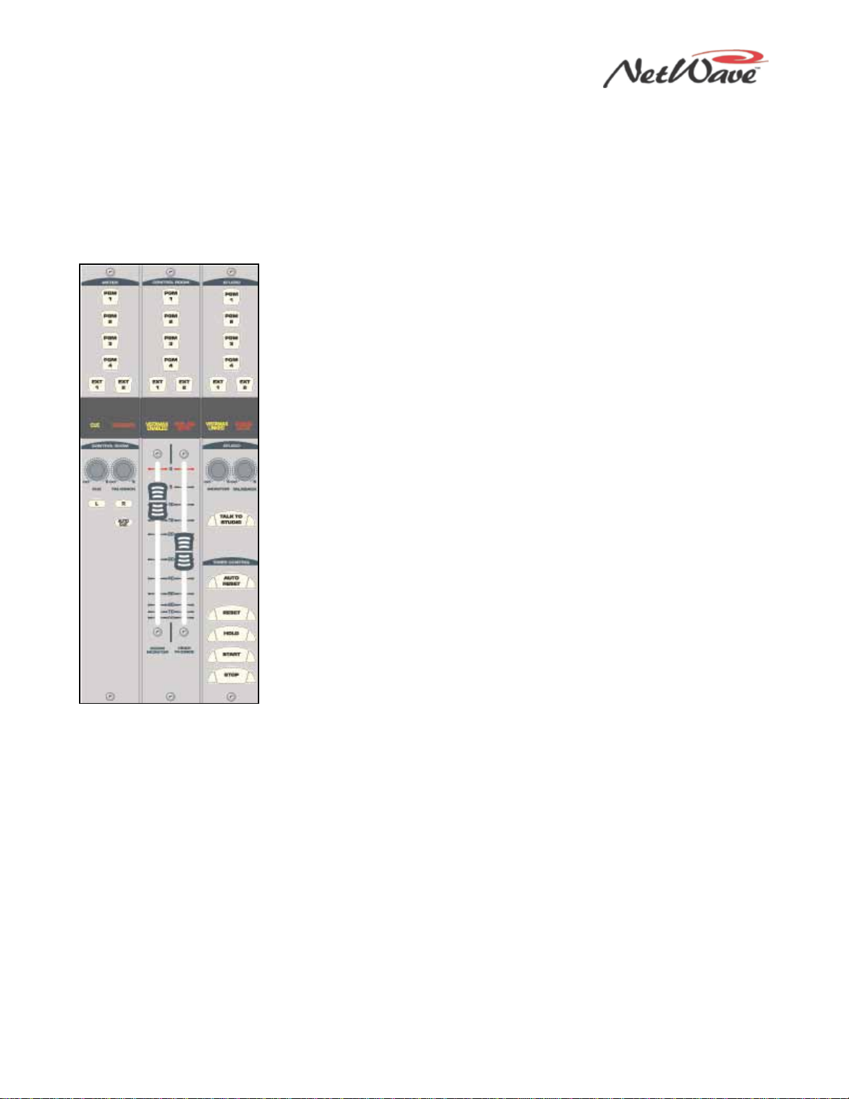
Figure 1-7. Monitor
Control Panel
Monitor Control Panel
This standard panel (Figure 1-7) is divided into three sections separated by double graphic lines. These
sections, listed from left to right and divided by main function, are
●Auxiliary Meter section
●Control Room (CR) section
●Studio section
Auxiliary Meter Section
The top portion of all three sections has exclusive action source selector
buttons to select one monitor signal from between the PGM 1 thru 4 buses
and the two External Monitor inputs. In the Meter section, the buttons select
which signal feeds the right-most meter in the Console Display, with the
selected source name shown below the Auxiliary Meter. The Auxiliary Meter
is typically set to alternately show the cue levels while cue is active; the
Cue label lights, and the cue level is shown in the Auxiliary Meter section
with the name Cue below the meter.
Several CR controls are located below the meter selector buttons in this
section of the panel. The Control Room Section covers these controls.
Control Room Section
The middle of the panel has the Control Room (CR) monitor source selector
buttons and the two faders to adjust the level of the room monitor speakers
(left fader) and the operator headphone outputs (right fader). Any one
source can be selected, which feeds all control room monitor outputs. The
active source selection button lights to indicate it is active.
A cue speaker, mounted within the console display, is level controlled by the
Cue pot in the middle of the left-hand Auxiliary section of the panel. A
yellow Cue label, just above the pot, lights while cue is active on any
channel.
A Talkback pot controls the level of incoming talkback that feeds the cue
speaker, independently of the Cue volume pot. A red Talkback label, just
above the Talkback pot, lights when the control room is receiving talkback.
The Monitor Mode buttons, also in the left-hand section, below the cue and
talkback pots, set the signal mode for all CR and studio outputs. The Land
Rbuttons control whether the monitor outputs are stereo (neither button is
lit), left only (L is lit), right only (R is lit), or a mono sum signal (both are
lit).
Just below the R mode button is the AutoCue button. When this button is lit, the operator’s headphone
output automatically switches to feed the cue bus into the operator’s headphones when cue is active. When
unlit, cue activity does not affect the board operator’s headphone audio.
AutoCue has two operating modes (set by multi-switch DS1, switch 3 on the Monitor & Output card). The
default setting is Split Cue, where the cue audio goes to one ear and monitor audio is summed to the other
ear. This is typically used when the console is in an on-air studio. The alternate mode is Stereo Cue, where
stereo cue audio replaces the monitor audio source in the headphones. This setting is typically used in
production rooms and other off-air applications.
Studio Section
The right-hand section of the Monitor Control panel has the monitor source selection buttons and level
controls for a separate talk or voice studio. You can select a source from among the six buttons at the top of
this section. The active source button lights when selected.
The two pots in this section control the output level of a dedicated studio monitor output (Monitor) and the
amount of talk to studio audio (Talkback) that is fed to this monitor output.
NetWave DirectView Broadcast Console Operations & Technical Manual
Revision A 1 - Introduction
Harris Broadcast 1-7 PR&E
The Studio Section also has a Talk to Studio button to allow the board operator to talk to the studio using
the board operator mic. You can assign multiple control room mics to also be talk sources to enable both a
board operator and a producer to talk to the studio while someone presses the Talk to Studio button.
Five event timer control buttons are at the bottom of this section. Start, Stop, Hold, and Reset manually
control the event timer in the Console Display. When the Auto Reset button is lit, the timer can be reset
automatically when a channel is turned on that has the Timer Reset option assigned. (The DSP card setup
controls set which channel sources reset the timer.)
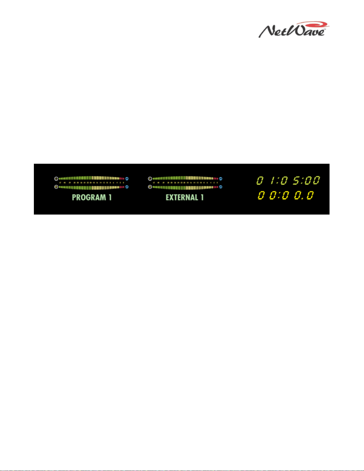
Console Display
The Console Display (Figure 1-8) has either two or four stereo bar graph meters:
●The left meter always shows the PGM 1 bus level.
●When four meters are present, the next two meters show the PGM 2 and PGM 3 bus levels, respectively.
●The right one, the Auxiliary Meter, shows a source selected using the Meter source buttons on the
Monitor Control panel (PGM 1-4, EXTERNAL 1, EXTERNAL 2, and CUE).
Figure 1-8. Console Display
The Console Display includes a clock and event timer. The default operating mode for the clock is
autonomous; the clock runs independently and must be set by hand. The clock time remains current for
about three days with the console powered off. After that, the time must be set again. The clock can
alternately be slaved to a SMPTE, ESE TC-89, or ESE TC-90 master clock. In the slave mode, the time set
buttons are not active. The event timer is manually controlled by Monitor Control panel buttons and, when
the Auto button is lit, by timer reset commands from one or more fader channels.
Monitor & Output Card
Each NetWave console has one Monitor & Output card (Figure 1-2) with the user connections listed
previously. The Monitor Control panel plugs into the Monitor & Output card, receiving power while sending
and receiving control signals. The card also connects to the DSP cards via a short, flat cable jumper to
supply power and clock signals and to send and receive bused audio signals. The Monitor & Output card has
two LEDs to indicate operational status (DSP clock and Fail) and a recessed console reset button.
This card is partly located below the Monitor Control panel and the Console Display. In normal operation, the
card connections are hidden below the flip-open rear cover.
DSP Cards
Each Digital Signal Processor card (DSP card – Figure 1-3) has the setup controls, audio input connectors,
and logic I/O connectors for eight console channels and for four Dual Fader panels that are mounted directly
in front of that DSP card. A DSP Active and a Fault LED indicate the card’s operational status.
There is one DSP card on a NetWave-8 console, two DSP cards on a NetWave-16 console, and three DSP
cards on a NetWave-24 console. In normal operation, the DSP cards are completely hidden from the
operator by the console display and the flip-open rear cover. All DSP cards are identical, except for the
leftmost card, which has a bus termination resistor pack installed in a socket (RN1) on the card.
Each DSP card has 12 RJ-45 jacks:
●Eight jacks, labeled red or blue, are located below the Dual Fader panels. The red jacks connect up to
four Dual Fader panels (using flat, red cables supplied with the frame). The blue jacks are only used to
connect flat, blue cables supplied with Dual Router and Dual Selector upgrade kits.
NetWave DirectView Broadcast Console Operations & Technical Manual
Revision A 1 - Introduction
Harris Broadcast 1-8 PR&E
●Four external RJ-45 jacks on the rear panel couple the optional Dual Selector or Dual Router panels to a
16x2 MicroRouter or to a VistaMax network switch port using customer-supplied CAT-5 cabling.
Each DSP card has a common set of assignment buttons and indicator LEDs to assign these parameters for
each A and B source on the eight channels associated with that DSP card:
●Input selection (Analog, Digital, or Network)
●Mode selection (Stereo, Left, Right, or Mono Sum)
●Signal function (Line Input, CR Mic, CR Mic as a Talk Source, Studio Mic, or Telco Input)
●Whether the logic I/O is active
●Input gain trims for both analog and digital inputs
●Network source assignment
●Additional logic parameter settings
Power Supply
Two types of power supplies are used with NetWave consoles. Each type has a single 48-volt DC output on a
keyed connector and uses a detachable IEC AC cord for 110 VAC/240 VAC, 50/60 Hz systems.
An in-line supply (PRE99-1206) is standard on the NetWave-8 and NetWave-16 consoles. It has a captive six
foot DC cable to allow the supply to sit below the console within the cabinetry. This supply is not
recommended for use on a NetWave-24 console.
NetWave-24 consoles ship with a rackmount Universal 48-volt DC Supply (PRE99-1205), which is also used
on VistaMax card frames and RMXdigital consoles. A 15-foot detachable DC cable (PRE90-1858-1) connects
this supply to the console.
One supply comes standard with each console. A second matching redundant supply can be connected to a
NetWave console by installing the optional PRE90-1995 Power Coupler.
Note: When adding a PRE99-1205 supply for redundant powering, order a PRE99-1205-1 supply,
since it includes the PRE90-1858-1 15-foot DC cable).
The Universal 48-volt DC Supply has a recessed front panel on/off switch and a green LED to indicate the
48-volt output is good. The PRE99-1206 in-line supply has a green LED on the top of its case to indicate its
48-volt output is good. It does not have a power switch. Each supply is designed for continuous 24/7
operation and is fully regulated and protected against excessive current by internal fuses and electronic
safeguards.
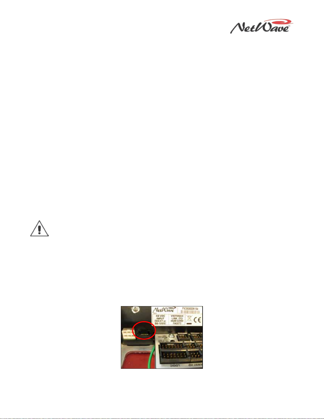
VistaMax Link
The RJ-45 VistaMax Link (Figure 1-9) connector, adjacent to the DC input connector on the rear panel, links
the NetWave console to a VistaMax, Envoy, or VMConnect Hub card, using a crossover CAT-5e or CAT-6
cable. You must install a Link or Link Plus Activation Kit to use the Link connector.
Figure 1-9. VistaMax Link

NetWave DirectView Broadcast Console Operations & Technical Manual
Revision A 1 - Introduction
Harris Broadcast 1-9 PR&E
The Link connector outputs four stereo program buses, stereo cue bus, the two-channel Telco record output,
up to six dual mix-minus signals, and one stereo source from each channel as VistaMax network source
signals. The Link can also input a source signal from the VistaMax network to each fader channel and the
two External Monitor inputs.
Specifications
Harris Broadcast reserves the right to change specifications without notice or obligation.
General
Measured on a fully populated NetWave-24 with 100k Ωloads on the analog outputs.
0 dBu=0.775 volts RMS, regardless of circuit impedance (0 dBm into 600 Ω). Noise measured using a 20
kHz bandwidth. Add 1.7 dB for a 30 kHz bandwidth.
Total Harmonic Distortion (THD+N) measured with swept signal, at +18 dBu, with a 20 kHz low pass filter.
FSD (Full Scale Digital) = 0 dBFS (digital output),+24 dBu (analog output)
Dimensions
All NetWave console mainframes are 3" [76] maximum height above the countertop, except for the console
display, which is 6" [152] high. The front-to-back depth of all mainframe sizes is 21" [533].
NetWave-8 is 20" [508] wide; NetWave-16 is 32.4" [823] wide; and NetWave-24 is 45.2" [1148] wide.
PRE99-1206 in-line supply for NetWave-8 and -16: 2" [51] x 3.8" [97] x 9.5" [241]
PRE99-1205 rackmount supply for NetWave-24 is 2 RU: 3.5" [89] x 19" [483] x 10" [254]
All dimensions - Height x Width x Depth, except as noted.
Power Supplies
Supply included with console: PRE99-1206 (NetWave-8 and NetWave-16) or PRE99-1205 (NetWave-24).
Optional Power Coupler (PRE90-1995) available for adding a matching redundant supply for on-air consoles
AC input voltage & frequency: 90-240 VAC, 50/60 Hz
AC input: detachable IEC power cord
DC output: a keyed, latching connector on a captive cable on the PRE99-1206 supply or a detachable cable
(PRE90-1858-1) on the PRE99-1205 supply
Rackmount or in-line power supply: grounded through the AC input cord ground pin
Console Power Requirements
Measured at 120 VAC/60 Hz
NetWave-8: 54 watts; NetWave-16: 99 watts; and NetWave-24: 141 watts
Required Supply Voltage & Current
NetWave-8: +48 VDC @ 1.2 amps; NetWave-16: +48 VDC @ 2 amps; NetWave-24: +48 VDC @ 3 amps

NetWave DirectView Broadcast Console Operations & Technical Manual
Revision A 1 - Introduction
Harris Broadcast 1-10 PR&E
Stereo Separation
Between Analog Program Outputs: >90 dB, 20 Hz to 20 kHz
Crosstalk Isolation
Program-to-Program bus: 85 dB, 20 Hz to 20 kHz
Frequency Response
Input to Program Output: +0.3 dB/-0.1 dB, from 20 Hz to 20 kHz
Dynamic Range
Analog Input to Analog Output: 106 dB referenced to FSD, 108 dB “A” weighted to FSD
Analog Input to Digital Output: 108 dB referenced to FSD, 110 dB “A” weighted to FSD
Digital Input to Analog Output: 108 dB referenced to FSD, 111 dB “A” weighted to FSD
Digital Input to Digital Output: 115 dB
Total Harmonic Distortion + Noise
Analog Input to Analog Output: <0.003%, 20 Hz to 20 kHz (<0.002% typical at 1k), +18 dBu input, +18
dBu output
Analog Input to Digital Output: <0.0009%, 20 Hz to 20 kHz, +18 dBu input, -6 dB FSD output
Digital Input to Analog Output: <0.003%, 20 Hz to 20 kHz (<0.002%, typical at 1 kHz), -6 dB FSD input,
+18 dBu output
Digital Input to Digital Output: <0.0005%, 20 Hz to 20 kHz, -6 dB FSD input, -6 dB FSD output
Analog Line Inputs
Input Impedance: >60k Ω, balanced
Nominal Input Level: +4 dBu (each input can be independently trimmed by +/-15dB)
Input Headroom: 20 dB above nominal input
Analog Line Outputs
Output Source Impedance: <3 Ω, active balanced
Output Load Impedance: 1k Ωmin.
Nominal Output Level: +4 dBu
Maximum Output Level: +24 dBu
CR & Studio Monitor Outputs
Output Source Impedance: <3 Ω, active balanced
Output Load Impedance: 1k Ω minimum
Nominal Output Level: +4 dBu
This manual suits for next models
4
Table of contents


