HARVARD 50-9513 Manual

Publication #
Revision 0
Date 12/28/94
84 October Hill Road
Massachusetts 01746
Tel.: (508) 893-8999
Fax: (508) 429-5732
e-mail: bioscience
@harvardapparatus.com
Web Site: harvardapparatus.com
Operating and Maintenance
Instructions
Harvard
Isolated Preamplifier
Catalog Number:
50-9513

Table of Contents
Subject Page(s)
Caution/Warning Statement ............................................ 2
Introduction ....................................................................... 2
Specifications ..................................................................... 3
Operating Procedure:
Recording with Electrodes .......................................... 4
Siting and Fixing the Electrodes ................................ 5 - 7
Use with the Harvard Modular
Universal Oscillograph ................................................. 8 - 9
Use with the Harvard
Student Oscillograph .................................................... 10 - 11
Problems .............................................................................. 12
Service Information .......................................................... 12 - 13
Customer Contact Addresses ........................................... 13
Diagrams:
Figure 1 – Isolated Preamplifier Controls ................. 3
Figure 2 – ENG Electrode Positions ............................ 5
Figure3–EMG Electrode Positions ........................... 5
Figure 4 – ECG Electrode Positions ........................... 6 - 7
Figure5–Modular Universal Oscillograph
Controls ........................................................ 9
Figure6–Student Oscillograph Controls.................. 11
Figure7–Back Panel of Preamplifier ....................... 12

2
Important Notice
This unit is intended for use as a research or teaching tool
ONLY and is not authorized for use as a component in a life
support device or other clinical system. Therefore, neither
we nor our agents can be held responsible if this notice is dis-
regarded.
WARNING
50-6808 Harvard Surface Electrodes
When using Coupland-Davis type electrodes or ANY type of needle
electrode, ALWAYS STERILIZE THE ELECTRODES BEFORE AND
AFTER USE ON EACH SUBJECT to reduce the chance of skin
infections or blood-carried diseases being transmitted.
Introduction
The Harvard Isolated Preamplifier has been designed for ECG
(EKG), EMG, and ENG (EOG) recording with subject isolation. The
front end of the preamplifier is a battery operated opto-isolator.
The remainder of the circuit obtains its power from the host unit.
Therearetwo types of input: a 3-pin socket for ordinary differen-
tial applications, and a “5-lead” input for ECG limb selection, cou-
pled with a 7-position selector switch. There is a 3-position gain
selector and 3-position filter selector.
NOTE: When this Isolated Preamplifier is to be used with our
Universal range of Oscillographs or with either the 50-4027 or
50-4028 4-Channel Interface Adapter, the 50-5966 Isolator Interface
Unit is also required.
Specifications
Batteries 2standard 9 V “transistor radio” type (PP3 or
IEC designation 6LR61)
Inputs 5standard color coded ECG 2 mm pin type
sockets LA, RA, LL, RL, C. Also 3-pin socket
for general differential input applications
Lead Selector Standard 7-position ECG lead selector: I, II,
III, AVR, AVL, AVF, V
Filtering 3-position filter switch:
30 Hz 3dB down
150 Hz 3dB down
15 kHz 3dB down
Gain Selectable x10, x100, x1000
Other Facilities DC level control; battery level indicator;
choice of DC or AC coupling
Rear Panel Coupling lead for use with Harvard instru-
ments; battery housings
3
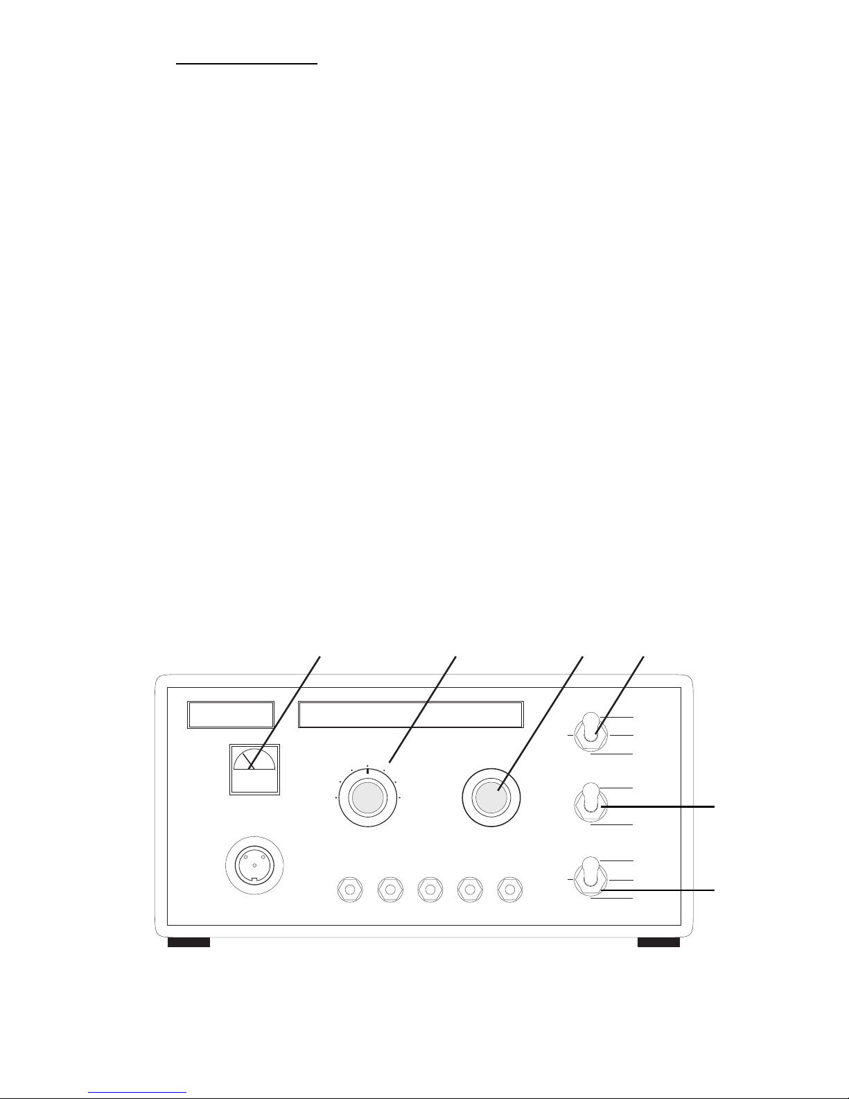
Figure 1
Isolated Preamplifier
INPUT
R.A. L.A. R.L. L.L. V
RED YELLOW BLACK GREEN WHITE
I
II
III AVR AVL
AVF
V
D.C. LEVEL
FREQ
CUT
GAIN
15 xHz
150 Hz
30 Hz
A. C.
D.C.
x1000
x100
x10
HARVARD
(4)(3)(2)(1)
(6)
(5)

4
Operating Procedure
Please note the “Important Notice” on page 2
The instructions that follow are for use with the Modular Universal
Oscillograph and the Student Oscillograph. To use the Isolated
Preamplifier with the Harvard Electrophysiological Teaching Unit,
please refer to the instruction manual supplied with that unit.
Points About Recording with Electrodes
Human Subjects: First, always clean the area of electrode applica-
tion with surgical spirit or similar, to remove grease, dirt, grime etc..
When using Coupland-Davis type electrodes or ANY type of needle
electrode ALWAYS STERILIZE THE ELECTRODES BEFORE AND
AFTER USE ON EACH SUBJECT to reduce the chance of skin
infections or blood-carried diseases being transmitted.
Always ensure that the electrodes are clean. This reduces noise on
your chart recordings.
Choose the siting of the electrodes carefully. Avoid areas of excess
fat (fat will reduce the amplitude of your signals).
Animal Subjects: If you are using needle electrodes, there is a
chance that a small DC voltage will develop at the electrode site
which may well “swamp” the input of the amplifier,causing the sig-
nal to get progressively smaller until it finally disappears. This can
be countered by connecting the 50-8390 Harvard Capacitor Box
between the electrodes and the Isolated Preamplifier.

Siting and Fixing the Electrodes
Fig. 2 below shows a suggested positioning of electrodes for ENG
(EOG). Note the positioning of the reference electrode (or zero volt
electrode). This electrode (within reason) can be placed anywhere.
5
For EMG, just place the electrodes over the group of muscles to be
monitored, see Fig. 3 below.
Figure 3
Figure 2
+
–
To 3-pin socket
on Isolated
Preamplifier
To3-pin socket
on Isolated
Preamplifier
Bicep
Ticep
Earth

}
6
Siting and Fixing the Electrodes (continued)
Fig. 4 on this page shows the conventional positions of electrodes for
recording ECG. You will notice that the patient’s RIGHT LEG is the
0 volt reference.
Essentially an ECG can be recorded from any part of the body, but
unless the conventional positions are used, the interpretation of the
results would be difficult. For more guidance, please refer to one of
the many books published which cover the recording of ECG wave-
forms.
2
1
3
45
6
Figure 4
0 volt
reference
black
green
red
blue
yellow
To Isolated
Preamplifier

7
AVL
I
AVR
II
III
AVF
V1
++
V2
+
+V4
+
+V5
V6
V3
–
–
–
–
–
–

Recording Waveforms Using the
Harvard Modular Universal Oscillograph
Numbers in brackets, e.g. (1), (2) etc. refer to Fig. 1 on page 3.
Letters in brackets, e.g. [A], [B] etc. refer to Fig. 5 on page 9 and
Fig. 12 in the Modular Universal Oscillograph Instruction Manual.
1) Have you read the complete Operating Procedure section?
2) Check that the Isolated Preamplifier is fitted with batteries
(see page 12).
3) Refer to Fig. 2, 3 or 4 on pages 5, 6 and 7 to apply the elec-
trodes to your subject.
4) Connect the electrodes to the Isolated Preamplifier using
either the 3-lead input cable or the ECG limb cable.
5) With reference to the Harvard Modular Universal Oscillograph
Instruction manual section 3.4.0, follow steps 1 to 13 inclu-
sive.
6) Plug the Isolated Preamplifier to the Isolator Interface.
7) Switch the Isolator Interface on and check that the battery
indicator (1) on the Preamplifier is in the green zone. If it is
not, refer to page 12.
8) Set the Preamplifier’s AC/DC switch (5) to the DC position
and set the filter switch to 15 kHz.
9) Set the Preamplifier's GAIN switch (6) to 10 and select posi-
tion I on switch (2).
10) Set the Oscillograph's Direct-OFF-Interface switch [AC] to
INTERFACE, the AC/DC switch [AA] to DC, the chart speed
control [T] to 2.5, and start chart drive by pushing chart drive
lever [M] to ON.
11) Adjust the Oscillograph’s GAIN control [W] to about 1. The
pen will move on the chart.
12) Adjust the Preamplifier’s DC LEVEL control (3) until the pen
returns to its central position on the chart. At this point you
should see a small waveform on the chart.
8
The amplitude of the waveform can be increased or decreased by
using the Oscillograph's GAIN control [W] and the Preamplifier's
GAIN control (6).
If either of the GAIN controls are re-adjusted, it may be necessary to
adjust the Preamplifier's DC LEVEL control (3) to bring the pen back
to the center of the chart.
Drift caused by the polarization of the electrodes can be overcome
by selecting AC on the Preamplifier's AC/DC control (5).
Filtering can be introduced using the Preamplifier's FREQ CUT
control (4).
If you are performing a 5-lead ECG you may select the various limb
configurations using switch (2).
Calibrate the waveform,using the Oscillograph's the CAL 0.1 switch
[Z].
This will cause the pen to move on the chart. The distance moved
by the pen when this switch is operated, is equivalent to 0.1 V (100
mV). You can now calculate how many mV equals 1 mm of pen
deflection. Let this equal d.
Measure the height of the waveform in mm. Let this value equal h.
Let g equal the gain selected on control (6).
Therefore the waveform (mV) = d x h
g
9
Figure 5
PEN ZERO
GAIN
2
3
456
7
8
9
10
1
0
MONITOR CAL. 0-1V. DIRECT INPUT
D.C.
A.C. DIRECT
INTERFACE
POLARITY
OFF
+
–
[W] [Z] [AA]
[AC]

Recording Waveforms with the
Harvard Student Oscillograph
Numbers in brackets, e.g. (1), (2) etc. refer to Fig. 1 on page 3.
Letters in brackets, e.g. [A], [B] etc. refer to Fig. 6 on page 11 and
Fig. 13 in the Student Oscillograph Instruction Manual.
1) Have you read the complete Operating Procedure section?
2) Check that the Isolated Preamplifier is fitted with batteries
(see page 12).
3) Refer to Fig. 2, 3 or 4 on pages 5, 6 and 7 to apply the elec-
trodes to your subject.
4) Connect the electrodes to the Isolated Preamplifier using
either the 3-lead input cable or the ECG limb cable.
5) With reference to the Harvard Student Oscillograph
Instruction manual section 3.4.0, follow steps 1 to 13 inclu-
sive.
6) Connect the Isolated Preamplifier to the INTERFACE socket [S]
on the Student Oscillograph.
7) Check that the battery indicator (1) on the Preamplifier is in
the green zone. If it is not, refer to page 12.
8) Set the Preamplifier’s AC/DC switch (5) to the DC position
and set the filter switch to 15 kHz.
9) Set the Preamplifier’s GAIN switch (6) to 10 and select posi-
tion I on switch (2).
10) Set Oscillograph’s AC/DC switch [N] to DC, the chart speed
control [L] to 2.5 and the chart drive lever [A] to ON.
11) Adjust the Oscillograph’s GAIN control [M] to about 1.
The pen will move on the chart.
12) Adjust the Preamplifier’s DC LEVEL control (3) until the pen
returns to its central position on the chart. At this point you
should see a small waveform on the chart.
10

The amplitude of the waveform can be increased or decreased by
using the Oscillograph’s GAIN control [M] and the Preamplifier’s
GAIN control (6).
If either of the GAIN controls are re-adjusted, it may be necessary to
adjust the Preamplifier’s DC LEVEL control (3) to bring the pen back to
the center of the chart.
Drift caused by the polarization of the electrodes can be overcome
by selecting AC on the Preamplifier’s AC/DC control (5).
Filtering can be introduced using the Preamplifier’s FREQ CUT
control (4).
If you are performing a 5-lead ECG you may select the various limb
configurations using switch (2).
Calibrate the waveform, using the Oscillograph’s the CAL 0.1 switch [Q].
This will cause the pen to move on the chart. The distance moved by
the pen when this switch is operated, is equivalent to 0.1 V (100 mV).
You can now calculate how many mV equals 1 mm of pen deflection.
Let this equal d.
Measure the height of the waveform in mm. Let this value equal h.
Let g equal the gain selected on control (6).
Therefore the waveform (mV) = d x h
g
11
Figure 6
PEN ZERO 8
GAIN
2
3
456
7
9
10
1
0
CAL. 0-1V. DIRECT INPUT
D.C.
A.C.
EVENT
INTERFACE
OFF
CHART SPEED
2
3
456
7
9
10
1
0
POWER
HARVARD
[L]
[Q]
[N]
[M]

Problems
If “noise” is seen superimposed on the waveform, then check the
following:
1) Have you sited the electrodes correctly? Check that the elec-
trodes are not sited on excessive fat. Check that they
are not sited over large muscles, otherwise, EMG will also be
displayed.
2) Check the earth or reference electrode.
3) Check that the correct leads are attached to the correct elec-
trode and correct socket on the Isolated Preamplifier.
4) If the Isolated Preamplifier is sited close to a main power lead,
then move one or the other or preferably both as far apart as
possible.
Service Information
Fitting or Replacing Batteries
The type of batteries required are 9 volt, size PP3 (IEC designation
6LR61) of the alkaline type.
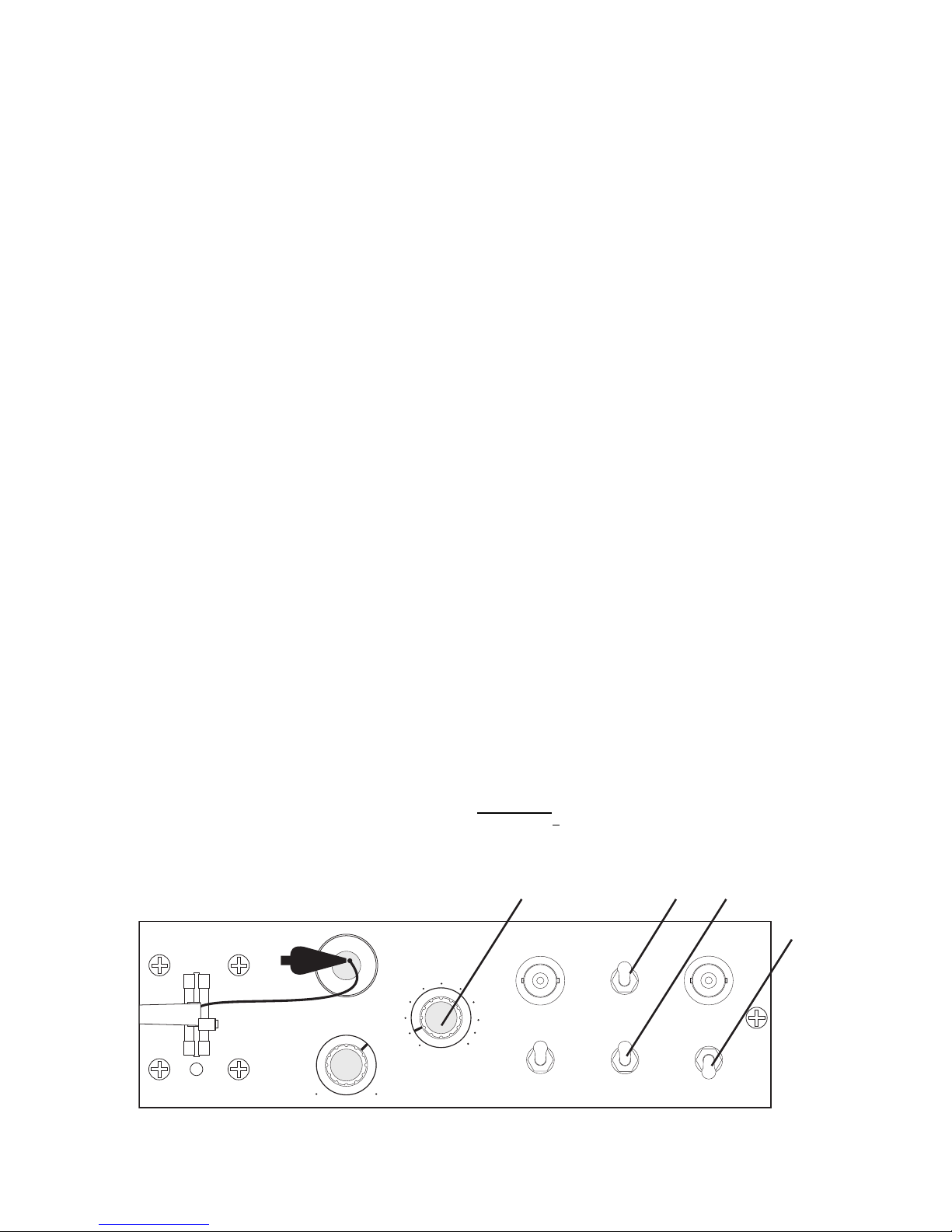
Locate the battery holders on the back panel of the amplifier (see
Fig. 7 below). Lift the plastic covers. Remove spent batteries and
connect new batteries to the connectors inside. Place the batteries
inside the holders and close the lids.
12
Figure 7
Lift here to gain
access to battery

Customer Contact Addresses
Customers located in the U.K., U.S.A., CANADA and FRANCE
In the event of a system breakdown, please contact our local office
(address etc. below) stating the nature of the fault and the approxi-
mate date of purchase, if possible.
Customers located in places other than listed above
In the event of a system breakdown, please contact our local agent
or, if one is not available, contact our U.K. office direct (telephone
number, fax number, telex number and address below) stating the
nature of the fault and the approximate date of purchase, if possible.
ENGLAND
Harvard Apparatus Ltd. Telephone: (0732) 864 001
Fircroft Way Fax: (0732) 863 356
Edenbridge Telex: 95292 SRI G.
Kent TN8 6HE ENGLAND
U.S.A.
Harvard Apparatus, Inc. Telephone: 508-893-8999
84 October Hill Road Toll Free: 800-272-2755
Holliston, MA 01746 USA Fax: 508-429-5732
CANADA
Harvard Apparatus Canada Telephone: 514-335-0792
6010 Vanden Abeele Street Toll Free: 800-361-1905
Saint-Laurent, Quebec Fax: 514-335-3482
CANADA H4S 1R9 Telex: 05-824064
FRANCE
Ealing S.A.R.L. Telephone: (1) 64 46 25 00
6 Avenue Des Andes Fax: (1) 64 46 94 38
Miniparc – Bât. 8
91952 LES ULIS Cédex FRANCE
13
Table of contents


