Haseman Electric R4D4 User manual

HASEMAN ELECTRIC
R4D4
USER MANUAL
Haseman R4D4 combines 4 relay outputs and 4
powerful universal dimmers (user selectable Leading /
Trailing Edge) produced by using of Z-Wave Plus the
latest version of Z-Wave.
WHAT IS Z-WAVE?
Z-Wave is international standard protocol for wireless
communication in smart homes and buildings.
Z-Wave enables smart home products to talk to each
other. This creates the backbone of your smart home
and enables you to use your smartphone or tablet to
create one-touch scenes that help with daily activities
like: saving energy keeping your home secure and
being more comfortable.
Z-Wave technology is simple: each transmitted
message is reconfirmed (2-way communication) and
every mains powered device can act as a repeater for
other devices (mesh network). The more Z-Wave
products you have in your smart home the stronger
your smart home network is.
Z-Wave technology is the leading solution in smart
home automation. There is a wide range of Z-Wave
devices that are fully compatible independently of the
manufacturer. It gives the system the ability to evolve
and expand over time.
SAFETY INFORMATION
Read this manual before attempting to install the
device! Failure to observe recommendations included in
this manual may be dangerous or cause a violation of
the law.
The manufacturer will not be held responsible for any
loss or damage resulting from not following the
instructions of operating manual.
DANGER OF ELECTROCUTION!
All works on the device may be performed only
by a qualified and licensed electrician. Observe
national regulations.
The device is designed to operate in electrical home
installation. Faulty connection or use may result in fire
or electric shock.
Even when the device is turned off voltage may be
present at its terminals.
Any maintenance introducing changes into the
configuration of connections or the load must be
always performed with disabled fuse.
CONNECTION DIAGRAMS
When connecting the module observe the
proper Neutral (N) and Line (L) terminals.
Each relay channel has its own Input (In) and
Output (O) which allows controlling of
devices supplied by different voltages (12
24 48VDC / VAC 110-240 VAC etc.)
During operation each channel status
is indicated by a panel indication LED.
INSTALLATION
Mount the module on standard DIN Rail.
Connect the local control lines S1 to S8 (if local
control is used). Depending on the BUTTON TYPE
Parameter (separate for each Channel) Push Buttons
or Toggle Switches can be connected:
Only Volta e Free contacts must be connected
between terminal Com and terminals S1 to S8.
Connect the controlled lines. Depending on the load
type (Dimmable or On-Off) load power and supply
voltage use one of the following connection diagrams.
DIMMER OUTPUTS (CH. 1 – CH. 4):
For dimmable li hts up to 500W per channel:
For dimmable li hts up to 300W per channel:
RELAY OUTPUTS (CH. 5 – CH. 8):
For 230V On/Off controllable loads:
For low volta e AC/DC loads:
For On/Off controllable loads with current
consumption more than 10 Amps:
When necessary the dimmer channels (CH.1
to 4) can also be used to control not
dimmable loads in On/Off Mode by
configuring the channel as a TRUE SINE (see
configuration parameters below).

Z-WAVE NETWORK
Z-Wave uses a mesh network topology where any non-
battery powered device acts as a signal repeater
enabling reliable connections from one node to the
other. Battery powered devices do not act as repeaters
as this would result in high levels of battery drain.
The frequencies used for Z-Wave are below that of the
normal Wi-Fi band and this enables better penetration
of walls and other items found in all homes but in
addition to this the mesh network means that the
transferred data can intelligently routed by the
network to get around obstacles and thereby obtaining
robust whole-home coverage.
Z-Wave typically has a range of about 50 meters in
open air. However walls and other items in the home
will considerably reduce this and therefore it is
recommended that the maximum device spacing Z-
Wave network is around 10 meters. Anything closer
will provide better communications.
In order to have a hierarchy within a wireless network
various types of Z-Wave device are specified:
Controller
As the name implies these devices are those that
control other Z-Wave devices. Controller devices are
factory programmed with a Home ID which cannot be
changed by the user.
Slave
Slave devices are those that are controlled by
controllers. Slave devices do not have a pre-
programmed Home ID but instead they take the Home
ID assigned to them by the Z-Wave network controller.
Routin slave
This form of Z-Wave slave is one that knows its
neighbors and has partial knowledge of routing table.
It can reply to the node from which it has received the
message. It can also send unsolicited messages to a
number of predefined nodes to which it has routes.
Z-Wave networks can be linked together for even
larger deployments. Each Z-Wave network can support
up to 232 Z-Wave devices allowing the flexibility to
provide sufficient devices for a complete automated
home.
Z-WAVE NETWORK
INCLUSION / EXCLUSION
On factory default the device does not belong to any
Z-Wave network. The device needs to be added to an
existing wireless network to communicate with the
devices of this network. This process is called
Inclusion. Devices can also be removed from the
network. This process is called Exclusion. Both
processes are initiated by the primary controller of the
Z-Wave network. This controller is turned into
exclusion respective inclusion mode. Inclusion and
Exclusion is then performed doing a special manual
action right on the device.
INCLUSION
Bring the module at max. 1 meter distance from
the main controller.
Connect the module to power supply.
Set the Z-Wave controller into INCLUSION mode
(adding new device to the Network).
Triple click the Z-Button on the front panel.
Be patient until the inclusion process is
completely finished. Multichannel devices
usually need a bit more time for complete
confi uration.
R4D4 also supports Auto Inclusion (by
switching On its power supply while the Z-
Wave Controller is in Inclusion Mode).
After the inclusion it will appear a separate instance
(Node) for each relay and dimmer channel. All
module parameters are set to their default values
(see the configuration parameters below).
You can hide unwanted Nodes and rename those
which you need. Depending on the model of your
main controller you can also edit Node icons in order
to suit your current project needs.
EXCLUSION
Bring the module at max. 1 meter distance from
the main controller.
Connect the module to power supply.
Set the Z-Wave controller into EXCLUSION mode.
Triple click the Z-Button on the front panel.
After the EXCLUSION all configuration
parameters of the module will be reset to their
default values.
CONFIGURATION PARAMETERS
This Z-Wave product is designed to work out of the
box after inclusion. However certain configuration can
customize its functionality and fit it to your specific
project needs.
Configuration parameters are accessible
from the main controller User Interface
(UI). You should find detailed instruction on
configuration procedure into your main
controller User Manual.
When proceeding with parameter modification please
refer to the parameter Range and Data Type as they
are specified below
POWER UP MEMORY (separate for each channel)
When Power Up memory is active the module will save
actual status of all outputs in case of power break.
After restoring the supply all outputs will be switched
to their previously saved statuses.
Parameter No: 64 to 71 (for Channel 1 to 8)
Data type: 2 bytes
Default value: 0 (inactive)
Available Settings:
1 – ACTIVE
0 (or any other number) - INACTIVE
BUTTON TYPE (separate for each channel)
Parameters No: 72 to 79 (for Channel 1 to 8)
Data type: 2 bytes
Default value: 1
Available Settings:
1 – PUSH BUTTON
On dimmer channels:
- Short press is switching On/Off.
- Long press is Dimming / Brightening.
- Double press is directly switching to MAX LEVEL
On Relay channels - each press is changing the
output status from ON to OFF or vice versa).
2 – TOGGLE SWITCH. Each changing of the switch
position will change the Output between ON and OFF
statuses.
3 – FOLLOWER SWITCH. The output is following
the status of the switch: open switch – inactive output
closed switch – active output.
4 – PULSE. This value is available for the relay
channels only. When the button is pressed (or toggle
switch position is changed) the output is switching On
for 3 sec and then it’s switching Off.
ANY OTHER number will disable the local control of
this channel (remote control over the Z-Wave network
will remain active).
DIMMING MODE (separate for each channel)
Parameters No: 80 to 83 (for Channel 1 to 4)
Data type: 2 bytes
Default value: 0 (Trailing Edge)
Available Settings:
0 – TRAILING EDGE
1 – LEADING EDGE
Leadin Ed e mode is suitable for resistive and
inductive loads (conventional incandescent and halogen
light bulbs ferromagnetic transformers).
Trailin Ed e control is suitable for capacitive loads
(dimmable FL Tube lights CFL with electronic ballast
electronic transformers dimmable LED light (check the
maker recommendations).

SOFT START (separate for each channel)
Parameters No: 84 to 87 (for Channel 1 to 4)
Data type: 2 bytes
Default value: 1
Available Settings:
0 – DISABLED
1 - ENABLED
MIN LEVEL (separate for each channel)
Parameters No: 88 to 91 (for Channel 1 to 4)
Data type: 2 bytes
Default value: 1
Available Settings: 1 to 98
MAX LEVEL (separate for each channel)
Parameters No: 92 to 95 (for Channel 1 to 4)
Data type: 2 bytes
Default value: 99
Available Settings: 2 to 99 or 555
MAX Level must be > MIN Level. In case a
wrong value is configured by the user the
parameter will be reset to its default value.
TRUE SINE MODE (555)
If the MAX LEVEL (parameter 92 to 95) of a dimmer
(CH 1 to 4) is set to value 555 such a channel will
operate in ON/OFF Mode with a real 100% sine on the
output when the channel is ON (TRUE SINE) instead
of 99%.
This option allows the usage of a dimmer channel as a
SSR (solid state relay) in order to control not
dimmable loads in On/Off mode.
The major advantages of this mode are the
arc prevention switching and suppression of
the high inrush currents. The option can be
used for frequently switching loads with a
total consumption less than the dimmer maximum
rated power.
Sample confi uration screen in Z-Way UI.
Sample confi uration screen in Fibaro HC UI:
ASSOCIATIONS
Associations provide direct control of other devices
within the Z-Wave network using the switches
connected to the module inputs.
Association ensures direct transfer of control
commands between devices i.e. it is
performed without participation of the main
controller and requires associated device to
be in a direct range.
ASSOCIATION GROUPS:
Association Group 1 (Lifeline)
Reports state of the device.
The main Z-Wave+ network controller is
added to this group by default. It is not
recommended to modify this group.
Association Groups 2 to 9 (User Groups 1 to 8) are
assigned to switches S1 to S8 respectively.
The module sends BASIC command class frame
(On/Off/Last Dimming Value) following the state of
the corresponding Output 1 to Output 8 (behavior
depends on the value of the configuration parameter
for the Button Input type (parameter 72 to 79).
OVER TEMPERATURE PROTECTION
If the max load of the dimmer channels exceeds the
module rated power or the ambient temperature in
the panel is too high the module over temperature
protection will automatically disable the dimmers
operation at 95°C temperature of the heatsink. Over
temperature will be reported to the Z-Wave controller.
Dimmer operation will be enabled only when the
heatsink temperature decreases to less than 85°C
(the outputs will remain Off until On command is sent
by the user).
Active over temperature protection will be also
indicated by a flashing LED indicators of the
dimmer channels (running light).
Sample view in Z-Way UI:
CONFIGURATION
PARAMETER No
DIMMER CHANNELS RELAY CHANNELS
CH. 1 CH. 2 CH. 3 CH. 4 CH. 5 CH. 6 CH. 7 CH. 8
Power Up Memory
64 65 66 67 68 69 70 71
Button Type
72 73 74 75 76 77 78 79
Dimmin Mode
80 81 82 83
* * * *
Soft Start
84 85 86 87
* * * *
MIN Level
88 89 90 91
* * * *
MAX Level
92 93 94 95
* * * *
Sample view in Fibaro Home Center:
Sample view in Vera controller:
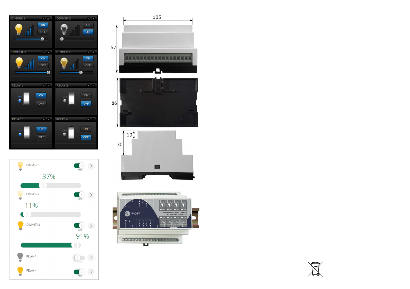
ENCLOSURE DIMENSIONS (mm)
DIN RAIL MOUNTING
COMMAND CLASSES
• Basic • SwitchBinary • SwitchMultilevel • Version
• SensorBinary • ZWavePlusInfo • Association
• AssociationGroupInformation • MultiChannel
• Configuration • PowerLevel • FirmwareUpdate
• ManufacturerSpecific • MultiChannelAssociation
WARRANTY
We warrant that the device is free from defects in
parts and workmanship under normal use for 24
months from date of purchase. The original purchase
invoice or sales receipt is the proof of date of purchase
by the Customer.
If the Device has manufacturing defects or in any case
of alleged lack of conformity the Customer shall send
a claim. Once we receive the Warranty Claim we must
inform the Customer if the Warranty is applicable and
the address where the Device shall be sent in order to
verify the defects (if any). The Device shall be sent by
the Customer at its own costs and expenses and with
the original packaging the supplied accessories and
documents proving date of purchase. We must then
inform the Customer about the defects and on its
repair or replacement (where applicable). The
Warranty Period of the replaced or repaired Device
shall not be extended. We will ship the repaired or a
replaced Device to Customer freight prepaid. We will
not be liable for damages to property caused by faulty
device. We will not be liable for indirect incidental
special consequential or punitive damages or for any
damage including inter alia loss of profits savings
data loss of benefits claims by third parties and any
property damage or personal injuries arising from or
related to the use of the Device. If the Device cannot
be replaced with another of the same type (e.g. the
Device is no longer in production or no longer available
for selling in the Customer’s country) it may be
replaced with a different one having similar technical
specifications to the faulty one. Such replacement shall
be considered as a total fulfillment of our obligations.
Warranty exclusion:
- Defects caused by normal wear of parts or especially
subject to wear such as parts that require periodic
replacement during the normal operation of the
system;
- Splits cracks scratches dents scratched or
discolored surfaces and parts breakage of plastic parts
and any other cosmetic damage;
- Damages resulting from use of the system other
than that provided including but not limited to the
failure to follow instructions contained in the operating
manual;
- Damages caused by accident abuse misuse dirt
viruses liquid contact fire earthquake improper or
inadequate maintenance or calibration negligence or
other external causes;
- Environmental damage and/or defects caused by
smoke dust dirt or other external influences;
- Damages caused by modifications and alterations in
the functionality or features;
- Damages resulting from transportation or
inadequate packaging when returning the product to
an authorize service center;
- Damages resulting from surges in the power network
or improper connection to the grid in a manner
inconsistent with the operating manual.
- Damages caused by operating or storing the device
in extremely adverse conditions such as high
humidity dust too low (freezing) or too high ambient
temperature;
- Products whose warranty sticker has been removed
damaged or rendered illegible;
- Expiration of the Warranty Period.
If a defect is not covered by the Warranty we will
inform the Customer about the extra expenses for the
repair or replacement.
TECHNICAL SPECIFICATIONS
4 dimmable outputs with user configurable dimming
mode – Leading or Trailing Edge (individual setting
for each dimmer channel).
4 Relay Outputs capable to control AC or DC loads.
High quality low RDS MOSFET power transistors.
Durable relays with long life contact system.
Zero Cross switching provides long relay life and
suppressing of any high inrush currents.
Over temperature protection.
User configurable Power Up Memory function.
User configurable button type - push button toggle
switch or follower switch (individual setting for each
channel).
User configurable Soft Start (individual for each
dimmer channel).
User configurable MIN and MAX dimming levels
(individual for each dimmer channel).
Power Supply range: 110-240VAC 50Hz.
Maximum power ratings:
Dimmer channels (CH. 1 to 4):
- 500W/channel (at 25°C ambient temperature).
. - 400W/channel (at 35°C ambient temperature).
Relay channels (CH. 5 to 8):
- Max. AC output: 10A / 110-230V (resistive load).
- Max. DC output: 12A / 12-30VDC.
16A rated PCB power tracks and terminals.
Front panel LED indication of active outputs.
ABS enclosure for standard DIN Rail mounting.
Durable tactile button on the front panel.
Dimensions: 105x86x57mm.
Conforms to EU regulations: EN55022 EN610006.
Radio protocol: Z-Wave Plus GEN 5 868.42MHz.
Antenna range: up to 50m outdoor / 30m indoor.
DISPOSAL GUIDELINES
The product does not contain hazardous chemicals.
Do not dispose of electrical appliances as
unsorted municipal waste use separate
collection facilities. Contact your local
government for information regarding the
collection systems available.
Popular Switch manuals by other brands

SMC Networks
SMC Networks TigerSwitch SMC6128PL2 Management guide

Cisco
Cisco 3750-24PS - Catalyst Switch - Stackable datasheet

TP-Link
TP-Link Omada DS105G-M2 installation guide

3Com
3Com SuperStack II 3C16670A user guide

Toyama
Toyama T13H-125B installation manual

Cisco
Cisco Catalyst 2820 Frequently asked questions


