Hatz BEAM E4 Advance User manual


WARNING!
(~~)
An RIC Helicopter is not a toy.
(RIC
~2.I~EH=
8ee.!-
~H::,f~OI
Of'8LICf.)
A radio controlled helicopter is a technical machine, operating at high RPM and
velocity.
(.~t!~l'H,!IJlc
:2",.
:2§J~5::§'.
6!§ofe
JIJjlgJLICf.)
It requires specialized skill and knowledge
in
its assembly, operations and
maintenance.
(~Ei,
6!§.
~:AI';C*~
~DHMe
~\i11E!
JI~J2I
:A1~OI
B:;:>~LICf.)
It
is
the user's responsibility to assemble, operate and maintain it
in
a safe manner,
without endangering the user or others.
Because the manufacturer has
no
control over its assembly, operation and
aintenance, the user assumes full responsibility for any and
all
claims, including
damages, bodily injury, death, or property damage, caused
by
the assembly,
operation and maintenance, whether negligence
is
present or otherwise.
(M*:AfLf
Cfe
MEi
011
Jil
~loHJf
JI:AI
eJ:2
2f~ofJiI
~JI~
~Ei,
6!§,
~:Zl.'r:*ofe
~g
fH~:Af~
:2igjgJLICf.
Ail~Me
~JI9-1
~Ei·.
6!§.
~:A1.'r:*0I1
2!()j~
*
:i'.!JI
[JI~OII
~JI~
~Ei,
6!§.
~:AI
';C*S'."f!Ei
\1i~ofe
~DH.
Mgj,
AHt!
ej]
§~
£~E!
(}iITiE!
~H~SO
Af*:Af~
-'!igjOlI
"'oVIl
~LlCf.)
By assembling, operating and maintaining the Beam
E4
Helicopter, the user
or person assembling, operating and maintaining the Beam
E4
Helicopter
indemnifies and agrees to hold harmless Beam
Inc.
and any of its employees,
distributors, dealers and agents from any and all claims asserted based on the
manufacturing, quality, assembly, operation and maintenance
of
the Beam E4
Helicopter. (Af*:AIJI
~
E4
~JI~
~Ei,
6!§.
~:AI.'r:*~
~Cfe
~g
~
Af~
J:!*2!,
*gJ~.
~c~.
::::OH~OI
gJ
E4
~JI~
Ail~.
~~.
~Ei.
6!§.
~:AI.'r:*'i'1
2!~i\H
(}i[iEl
~H~~:;:>~
;!igjSO
:AI:AI
PJ
1§
011
§~~~
9-IOI~LICI.)
Because of the potential for harm, the utmost care must be used
in
its assembly,
operation and maintenance, as one would with its full-scale counterpart.
It
is imperative that the user read these instructions carefully and understands
the associated danger of such occurrences as fire, bodily injury, death and
property damage.
woH9.J
~1~OI
£15::'='.S'.
fi<t!~§~JI~
~Ei.
6!§.
~:AI';C*OIle
~Ail
~JIOII
B:;:>£Ie
~:ilf
Of~Jf:Al§'.
e
"'?9-IJf
.2:;:>~LlCI.
Af*:Zfe
~~M~
Ail~of)1I
~:AIDHO~2fof[Jj
~JI'i'I
2!~DH
:2.IAH.
~DH.
Mg,>,
AW~9-1
e~:ilf
gg
~~Ol
'§j(}i'§t * £1Cfe
2j~
~~DHO~
gLlCfj
If for any reason you cannot agree or comply with the information contained
herein, return this product
in
saleable condition accompanied by a receipt within
1 year of purchase
to
the distributor below and your money, less and shipping
and handling fees will
be
refunded.
(Ol~~
LH*OII
§9.Jof:A1
§!'oft!Cfe! All§
:;:>OH
1~
OILHOII
2J*g:ilf
B>ml:;:>gJ
Ail§§
OIJH*
~EH
:::lOIS'.
OfcH
JIAH§
'1"gJx~OII
'2!~ofAIe!
~H§tll~
Ail'i'lE!
:;:>gJJf~~
§cl-,=cl1:l!i3L1Cf)
- 1 -

------
---
----
---
Table ofcontents
(~xf)
• Warning!
(~:L2)
.....•..............
1
~._---
• Table
of
contents
(~~f)
2
1.
Safety guidelines for the RIC helicopter (RIC
~2.1
§E1~
8:3!
JfOIEO) 3
1-1. Before a flight
(~I~m
3
1-2. During the flight
(~I~AI)
4
1-3. After the flight
(~I
~~)
4
2.
Tools needed & Additional items
(~~0I1
!!i£(~
'i:-T'2f
JIEf
§~)
5
3.
Assembly
(;;:;;~)
6
• Read before assembly
(;;:;;~:3!
;:;;~Af~)
6
3-1. Frame 7
3-2. Rotor
11
3-3. Gear 16
3-4. Tail 17
3-5. Etc.
21
4. Pitch and Throttle setting
(DHI2f
~£~
~~)
24
4-1. Pitch Range setting
(lIl~1
2(
~~) 24
4-2. Suggested RPM
of
the main rotor
(OII'2J£Ej~
~~
RPM)
24
4-3. Pitch curve setting
(1II~1
7l~
~~)
25
4-4. Pitch curve settings on the transmitter
($~JI~
lIl:!:1
3j'::'
~~
:J2H~)
25
4-5. Throttle curve settings
on
the transmitter
(~~JI~
::':£~
7i.'::'.
{g~
:J2H~)
26
5.
Movement
of
Transmitter Sticks and the Heli
($~JI
~~:ilI
~JI~
§~)
27
6.
Checkup points before flying
(~I~:3!
EM)
28
---"
-
-_
..
_---
7.
Data Sheet, 120· CCPM
(A11
~
[jl
01
En 28
8.
Tracking adjustment
(§ClI'bi~
~~) 29
9.
Selecting motor pinions
(2Ej2f
lIILI2!
JI()j~
~~)
29
10. Parts List
(¥§
~~)
30
10-1. Frame 30
10-2. Gear, Swashplate 32
10-3. Rotor 34
10-4. Tail 36
10-5. Etc. 39
11. Option Part
41
--_
..
_------_.
-
-_._-
-_.-
12. Flybarless System 42
-
2-

IT]
Safety Guidelines for the RIC Helicopter (RIC
~2.I~E~~
£f~
)fOI~)
1.
Beginners should get guidance and supervision from experienced flyers.
2.
Fly only at approved airfields.
Do
not fly at school, residential area or near roads, railways and
power lines.
(oD18
2!~OIIAl'2!
~I@~CI.
~:ll!.
?~,
C;::5".
~~.
@c:!C':!
2xiOilAle
~CIAI
aleCI.)
3.
Make sure there are
no
other pilots flying with the same radio frequency
as
yours.
Interference can
be
very dangerous to all.
(~~~
?IlI4'5"
~I@ole
Ala'OI
2x10¹¹
~eJ.:l
'iCf.<=AI
~'2!~Cf.
4.
Keep the helicopter at least 5-1
Om
away from the flyer for safety.
('2!C:!)jcle
~~
5-10MOI~
~AloiDt
tll@E!CI.)
5.
Do
not fly the helicopter behind
the
flyer himself.
(lO§AI
§!E:!~£
~JI~
~1@oIAI
aleCl.)
6.
Never fly near or above other flyers, spectators or cars.
7.
In
case of emergency, priority should be given to the safety of other flyers and spectators.
1-1. Before a flight
(~I@C:I)
1.
Make sure batteries
in
the helicopter and the transmitter to
be
fully charged before flying.
(~I~C:I
~JI2I
@t.lJI~
~HEicIJI
'2!~c:!01
901~eAI
~'2!E!CI.)
2.
Do
a range check ofthe radio before the first flight. The radio should work at least 20 meters
away from the helicopter with the transmitter antenna collapsed.
(?!~1@0I1
~Al
@t.I~~)jcl~
~'2!E!CI
~t.lJI~1
'2!ElILI~
~g
~EHOIIAl
~JI£'i'-Ei
~~
20m
~OI~
)jcIOiIAlC;::
~;\il~OI
~JIJI
~50HOIE!CI.)
3.
Inspect the helicopter thoroughly so that there are no missing or loose bolts.
Important checking points: linkages, rotor blades, motor, gears.
(~1@0I1
~Al
~JI~
Zf
'i'-'i'l~
~'2!011
~§JI
~~CI)jLI
UHj~AI
algAl
~'2!~Cf
iSH
~'2!
'i'-'i'l: [33IAI,
5"E1~21101-'=,
2Ei,
JIOI)
4.
If there
is
too much slops or breakage
in
the linkages, replace
it
with a new one.
The linkages should not
be
too loose or too tight and they just fit snugly.
5.
Carefully check that the rotor blades are not damaged or cracked, especially around
the hole ofthe blade holder. Check that the rotor blade
is
safely fastened.
(5"Ei~
All
2J
<5IJlI
~AloHA1
~ol,
5Cl
?~0I1
;:;01
~)jLl2~01
~~'2'I ~-'=AI
AH
5"85"
:il!!ie!CI.)
6.
Make sure the motor is fastened securely
to
the mount as
it
produces high degree
ofvibration.
(28e
~ol
PJg
~~§
~{!!01~5"
2EiJi
@t
:J:!2)901
~eAI
~'2!~CI.)
7.
Check that the servos operate smoothly and properly. (21 Al';:!JI
'i'--'=~JlI
;\1101£
§~oleAI
~'2!E!CI.)
Their malfunctioning may cause a loss of control that will result dangerous situation.
8.
Be
sure to keep the following sequences to turn
on
or
off
the power:
(C:I~~
~
[He
CI~
~Al~
[leCl.)
CD
When you start flying, turn
on
the transmitter first and then the heli.
® After flying, turn
off
the heli first and then the transmitter.
- 3 -

1-2. During the flight
(tJl~AI)
1.
We strongly recommend you to spend time
in
practicing the helicopter simulation program
before you fly the real model.
(2~~]1~
tJl~ol]1
~Oll
~
~IJI
AI~ClIOIC'1
!!~.:J~~
~;l:j
e!ecr']I~
l'!~~c'.)
This will get you confidence and will significantly reduce the cost of repair.
(OIi'JlI
~~~}'\i
UleOiI
[IE
*2.ltJlg~
3JlI
~~
-*
£.!CI.)
Keep practicing the simulation program and that will accelerate your learning curve.
2.
If you face any problem during the flight, force the heli down straight away.
(tJl~~OII
~AiIJ'
!§,~Ofe!
~AI
~IJI~
2011
~~AI~CI.)
3.
If there
is
other helis
in
the airfield, you are advised not to fly at the same time.
But if you really want
to,
make sure
to
check the radio frequencies
to
prevent interfering.
4.
In
case there are people or animals
in
the airfield, a flyer should pay special attention
to
these objects coming to him or the helicopter
as
the flyer usually occupy himself
in
the
flying only.
(1:J1~~0I1
CIE
Af~OILi
§~Ol
£.!~
f,l£f
OI~OI
]ImOI
CI]I2~:A1
~!;11crl
'?~~
]1~OlOI~CI.
~§:AI~
~]IOII~
2iUOI
~~9
Ol~~
@!
!:i'!:A1
,)"ol]IIDI§"OICI.)
1-3. After the flight
(tJl~~)
1.
Conduct a through inspection
on
the helicopter
to
insure
no
parts have come loose
or become damaged during the flight.
2.
Check the temperature of motor and battery.
(2Ei'?l
~HEi2.l~
g'Z.~
~~~CI.)
If they are too hot
to
touch, something goes wrong.
(OI~OI
LW
~Ji"i'~
]1;\jIOlI
~]I
~AilJl
£.!§~
~DI~[f.)
In
this case, you should find the problem and fix
it
before the next flying.
3.
Disconnect the battery from the speed controller.
If you leave the battery connected overnight, this will seriously damage the battery.
(t'!~]I~!;2Ei
~HEi2.1
Z:I'=!jEi~
lO"2.I~[f
.
.:J(jj~
~f,l"i'
~HEi2.IOII
~2{e!
2~~
'?JlI§CI.)
4.
When the helicopter has crashed, inspect,
in
particular, main rotors, tail rotors, main mast,
tail shaft, the flybar. and the feathering shaft.
If any part
is
damaged, it must
be
replaced with a new part.
(2~§
~gg
\:O!~AI
All
~g>?5'.
:ll2;\~lelCl.)
Do
not try to repair damaged or broken parts with glue.
The parts
in
the helicopter are under high stress due
to
vibration.
If parts fail during the flight, this will lead
to
a loss of control that
is
highly dangerous.
-4-

[:IJ
Tools needed & Additional items
(~~0I1
~Qe!
~-=jJ-2f
JIEf
~!:?,)
Tools needed
Socket Driver
Hex
Wrench Screw Driver
4)
Ball
Link Plier
(Small, Large) (5.5mm 2pcs)
(1.5mm,2.5mm) 7
/)
-_.#
..
,
~.
.~
_7
r
(/~
.--'-
//
~
c/
Ball
Reamer Pitch Gauge Gimlet (for canopy)
Long Nose Plier
_.----:>-
0,
....
~
~··-···-··
...•....
I··
/
//"/
~
..........
I
~/
l / ,
/ /
'-'-("
J
'/
~/
~
-~
~
~
C.A Glue Cutting Knife
Thread Lock Scissor
(Cyano Adhesive)
~
/7
-:-:;/1
~
~
~/
I~~/
I I
\(
.//
~/
l
..
//
I
~
Additional items
Transmitter
Motor
Receiver
Electronic Speed
Controller
Servo
Li-Po Battery
Gyro
Battery Charger
-5-

---------
---------
---------
-------
WAssembly
(~~)
• Read before assembly
(~iEJ~
-9-£IA~gj-)
1.
Before assembly, read the instruction manual thoroughly familiarizing yourself with
the model and assembly procedures.
2.
Check the contents of the box and make sure there is no missing part and all parts
are
in
good shape. After the packaging has been opened and parts have been used,
parts cannot be exchanged or returned.
(!;>{:'::2!~
LH~~~
~2!of:i}.
UUfl!
¥i§OI
~JiLf
3.
Tapping screws cut threads
in
the hole
of
the parts. When screws are difficult to tighten,
fasten the screw unit the parts
is
part
is
properly set. However, do not over-tighten
the screw to the point
of
stripping the threads or warping the part.
4.
Apply Locktite
(~EfOI§
Af~'iYtgj)
: Use Blue Locktite
(.:L1~JJI)
(Threadlock
on
all
screws)
~
:
Use
Red
Locktite
(~'?
.:L1~Jil)
~
: Use Cyano Adhesive glue (6:2f
~"um
5.
Check Rudder Servo Type
(em
Jd~
CI~)
~~---
l._
Micro
Rudder
Servo
(Nexus
DSW300
Series)
-r
I_".~~O
~
(Nexus
DSW600
Series)
\'"''''
R"dd"
s,~
I
I~?
~
..
~))(/
/~'
f:/
..
~
-
6-

I 3-1. Frame I
WJ
0
P""'9
P""'9
F_b::
::«-3
lTlTUlT
[flJ
~~~H
eeee
IT IT
IT
(UJ
@JJ
0== 0==
r=::Q:o:
) o
~~
-7-

~
Upper Bearing Block
@
[J:::::::::J
----- 2 pcs
Socket Head Bolt, 2x8mm
@
[J:::::J
------
2 pcs
Socket Head Bolt, 2x5mm
@0
.----
1 pc
Ball Bearing, #MR115zz
&.
Caution
@
IP
------ 2 pcs
Flat Head Bolt, 2x6mm
@
IP
-------- 2 pcs
Flat Head Bolt, 2x3mm
@ 0
---------
2 pcs
Ball Bearing, #MR52zz
Antirotation Plate
(1
pc)
Socket Head Bolt,
~
2x8mm
(2
pcs)
~
,.
~
:"'i'
"
~
...
/~
Socket Head Bolt,
Body Catch
-----------~,.
:
:/
.... 2x5mm
(2
pes)
(2
pcs)
,0
..
,~,Q
~
"~
Upper Bearing
------
~~~
:
Block
(1
pc) 0 :
((5)
Ball Bearing,
~
c::::r
#MR115zz
(1
pc)
[ill
Lower Bearing Block & Motor Mount
d Ball Bearing,
@0
-----
1 pc #MR115zz
(1
pc)
Ball Bearing, #MR115zz
~
Up
..L
IIaJaI
Up
..L
If?)
j;jl
&.
Caution
Mind the direction of
the Bearing Block.
Motor Mount
(1
pc)
Mind the direction of
the Bearing Block.
[ill
Belt Guide Pulley
~
~
n----
Flat Head Bolt, 2x6mm
(2
pes)
@,
Y®---Ball Bearing, #MR52zz
(2
pes)
H
--00--
Bot
Go;d,
Poll",
9.5
(2
Pc.)
+
~
Spacer, 3.5xO.7mm
(2
pes)
~
Crossmember, 30mm
(1
pc)
~"V
Pulley Support, 33mm
(1
pc)
~
Jr--
Flat Head Bolt, 2x3mm
(2
pes)
- 8 -
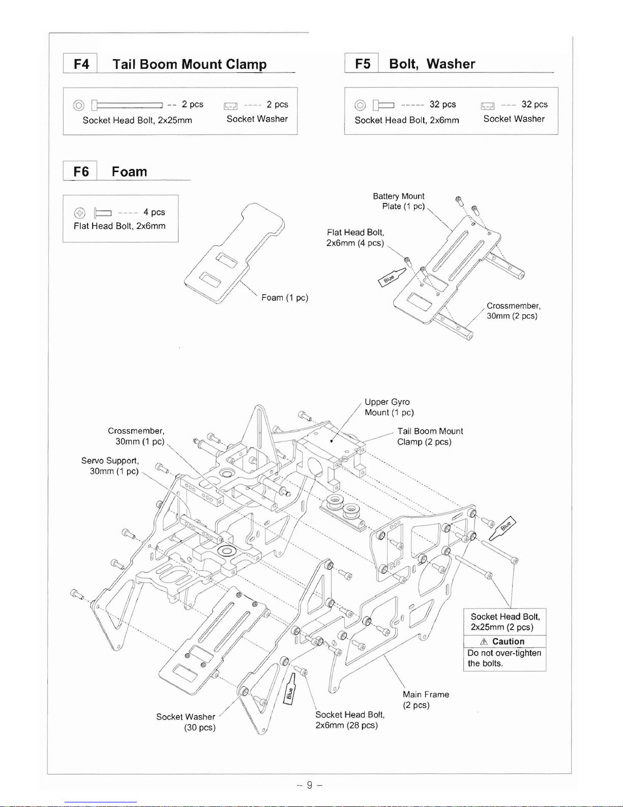
[£!J Tail Boom Mount Clamp
~
Bolt, Washer
@
[p
----- 32 pes g
---
32 pes
@ D i
--
2pes g
----
2pes
Socket Washer
Socket Head Bolt, 2x25mm Socket Washer Socket Head Bolt, 2x6mm
[£!] Foam
@ p ---- 4 pes
Flat Head Bolt, 2x6mm
Foam
(1
pc)
Battery Mount
Plate
(1
pc)
Crossmember,
30mm
(2
pes)
Upper Gyro
Crossmember,
30mm
(1
pc)
Servo Support,
rA
30mm
(1
pc)
~
~"
""-
~'
Socket Washer
(30 pes)
/ Mount
(1
pc)
\\a:,,==~::r-.<:-/
Tail Boom Mount
Clamp
(2
pes)
Socket Head Bolt,
2x25mm
(2
pes)
& Caution
Do
not over-tighten
the bolts.
Main Frame
(2
pes)
- 9 -

Self Tapping Screw,
2x7mm (4
pes)
Antenna Tube (L)
Landing Strut
(2
pes)
Socket Washer
(4
pes)
Socket Head Bolt,
2x8mm
(2
pes)
Socket Head Bolt,
I F7 -
Fal
Landing Skid & Main Frame Bottom Plate
@
~
------
4 pes @ p ------- 6 pes @
[p
------ 2 pes
SelfTapping
Screw, 2x7mm Flat Head Bolt, 2x6mm Socket
Head
Bolt,
2x8mm
Main Frame Bottom
Plate
(1
pc)
Antenna Tube (S)
Silicon Tube
$J
Landing Skid
(2
pes)
Landing Skid
~
P
Cap (4 pes)
'-0----
2x6mm
(4
pes)
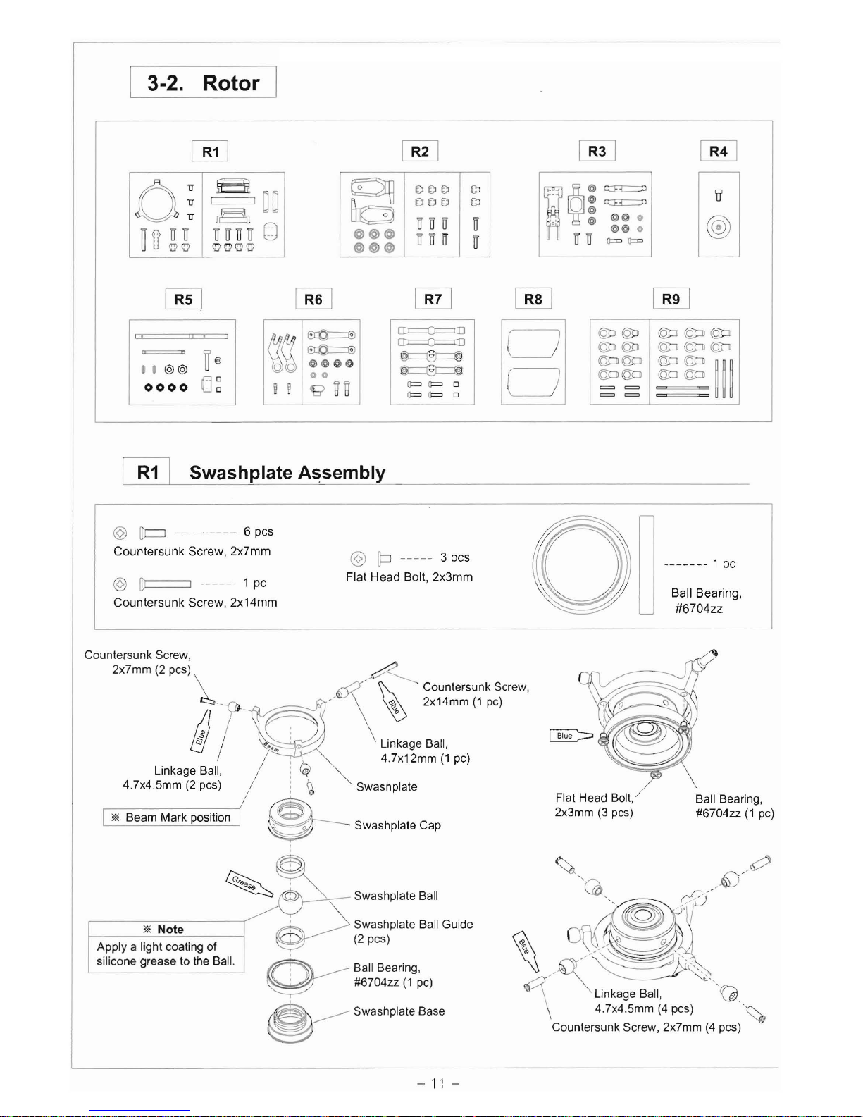
3-2. Rotor I
[ill
0:
g~~
r§
~
a
gg
UUUIT
[)
"''''''''''
~
i.
I
".
=
IT@
••
@@
00
0000
. 0
~
~~
ij ij
~
~
@@@@
00
~~
[B!J
~
~
~
DDD
GJ
0
DDD
GJ
UUIT
IT
@@@
@@@
ITITU
IT
"
O:~
'0' ;
@@
0
IRO
o =
@@
0
ITIT
==
~
[ill [ill
~
[D::::::::():::
[D::::::::():::
~
~
Q:= Q:=
0
Q:= Q:=
0 8
@:D @:D
@::li @::li @::li
@:D @:D
@::li @::li @::li
@::li@::li
@::li @::li
~~~
@::li@::li @::li @::li
==
==
[B!] Swashplate
A~sembly
@
[t=J
---------
6 pes
Countersunk Screw, 2x7mm @ [p
-----
3 pes
.------
1 pc
Flat Head Bolt, 2x3mm
@ [[t:::::=J .
--
-
-'
1 pc Ball Bearing,
Countersunk Screw, 2x14mm o #6704zz
Countersunk Screw,
2x7mm (2 pes)
~r
'~
~
~
Countersunk Screw,
~:2=:::::::;!v"
\
~
2x14mm
(1
pc)
~
. Linkage Ball,
4.
7x12mm
(1
pc)
Linkage Ball,
:~
4.7x4.5mm
(2
pes) !
~
Swashplate Flat Head Bolt, Ball Bearing,
2x3mm
(3
pes)
#6704zz
(1
pc)
* Beam Mark position
~
Swashplate Cap
Swashplate Ball
Swashplale Ball Guide
(2
pcs)
Apply a light coating of
~
silicone grease to the Ball.
0---
Ball Bearing,
~
~
#6704zz
(1
pc)
~
Linkage Ball,
'Vi>.
\ 4.7x4.5mm
(4
pes)
.~
~
Swashplate Base Countersunk Screw, 2x7mm
(4
pes)
* Note
-
11
-
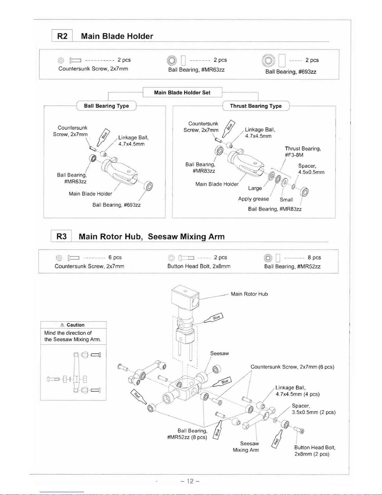
~
Main Blade Holder
@
IlJ::=J
---------- 2 pes © D
-------
2 pes @ 0
-----
2 pes
Countersunk Screw, 2x7mm Ball Bearing, #MR63zz Ball Bearing, #693zz
Main Blade Holder Set
[ill
Main Rotor Hub, Seesaw Mixing Arm
@
IP
-------- 6 pes @ Q::=o
-----
2 pes @ 0
-------
8 pes
Countersunk Screw, 2x7mm Button Head Bolt, 2x8mm Ball Bearing, #MR52zz
Main Rotor Hub
&. Caution
Mind the direction of
the Seesaw Mixing
Arm.
~D~
Q:=r::l-
-fi
t I
{]
.-o~
rt:::::tJ,
l:2
"
~,
3.5xO
5mm
(2
pes)
'a
11'(1"
Ball Bearing, !/
;fJ
#MR52zz
(8
pes)
as
Seesaw
,J
Bulton Head Bolt,
Mixing
Arm
2x8mm
(2
pcs)
Ball Bearing Type
Countersunk
SO",""
2><7m\~
;'~~~9;m"~"
t,,-'
Ball Bearing,
#MR63zz
Main Blade Holder
Ball Bearing, #693zz
Countersunk
I"
Screw,2x7mm
;3
/
~
d Linkage Ball,
47x45mm
{{6}"
r " Thrust Bearing,
#F3-8M
Ball Bearing, _ / Spacer,
#MR83ZZ',(@)~,
4
5xO
5mm
M,,"
61'd'
Hold"
/!~
j
APPI~a;~:ase
sm~1I
"rw
Ball Bearing, #MR83zz
-
12-

~
Head Button
~
Feathering Shaft, Main Shaft
@
[p
------ 1 pc @
O====J
-----
1pc @ ----- 1pc @
ldJ
-----
2 pcs
Socket Head Bolt, 2x4mm Socket Head Bolt, 2x11 mm
Nut,2mm
Nylon Nut, 3mm
Sockel Head
Bolt,
2x4mm
(1
pc)
~
/
";::1:':::
Sh,'
~
O-Ring -Soft
~
~--
~/~
o5x1.7mm -Ball Type
I
roo
-
J@L
"':p",,,
0
5,13mm
-
Th"'1
Typo
~---~
~
Soeket Head Bolt,
2x11
mm
(1
pe)
Nylon
Nut,
NUl,
2mm
(1
pe)
3mm
(2
pes)
Main Shaft
~
Washout Arm, Washout Base
@
/tC=l
------
2 pcs @
Q::::::o
----- 2
pes
@ 0
------
4 pcs
Counlersunk Screw, 2x8mm Button Head Boll, 2x8mm Ball Bearing, #MR52zz
@~
W
Sp",,,.
a2r~
C,",I,moo'
S,,~.
Washoul Link Boll,
1 7x7.5mm
(2
pes)
\
Washout Base
Washout
Arm
3.5xO.5mm
\ 2x8mm
(2
pes)
(2
pes)
!/%
Linkage Ball,
Bulton Head Boll, Ball Bearing, 4.7x5.5mm
(2
pes)
2x8mm
(2
pes)
#MR52zz
(4
pes)
-
13-

~
Flybar [B!] Flybar Paddle
@
(j:::::::::J
------
4 pes
Button Head Bolt, 2x7mm
---------------------
2 pes
@ 0
----------
2 pes
Washout
Arm
to Flybar Arm Spacer
Set Screw, 3x3mm (Linkage Rod 1.3x1Omm)
Set Screw,
3x3mm (2 pcs)
A
---
<-"
• -
__
--.----
~
~-
-.....:@/
~
~--~-
6:
./'
___
r\
--
Flybar
Control Arm
Flybar, 210mm
Button Head Bolt,
2x7mm
(4
pes)
Flybar Paddle,
(2
pes)
::'
-{I.L-
L1
Caution
[ill
Mintl the direction
of
the Flybar Arm Swashplate Assembly
Spacer to Flybar Control Arm.
~-
1
----'~
(p--
::'
-IT.'--I
_~
L1
Caution
Make sure both sides of
the Flybar are equal in length.
31\
80mm
Equal Distance
31\
80mm Equal Distance
+-

~
Linkage Rod, Ball Link
11.3 2.4
Washout Arm to Flybar Arm Spacer Seesaw Mixing Arm to Swashplate Cap
(Linkage Rod, 1.3x10mm) (Linkage Rod, 1.3x29mm)
13.4 21.2 13.4
13.4 2.6 13.4
----------
2 pes
29
48
---
2 pes
29.4
Main Blade Holder to Seesaw Mixing Arm Swashplate to Servo Arm
(Linkage Rod, 1.3x10mm) (Linkage Rod, 1.3x21mm)
--------
3 pes
-
------------
2
pes
Ball Link
(S),
11.3mm
(4
pes)
Ball Link
(L),
13.4mm
(14
pes)
'*
Note
Mind the direction of
the Ball Link
to
Linkage Ball.
~¢J-~
•
~
~T
Linkage Ball
Number mark Ball Link
& Caution
When the transmitter pitch stick
in
middle position.
Servo horn should
be
perpendicularity.
ll~1
~
-
15-

3-3. Gear
= @
ppp
[Q!] Main Drive Gear
@
[]::===:J
----~
1 pc <Nut, 2mm
(1
pc)
Socket
Head
Bolt,
2x11mm
©
~
----------
1
pc
Nut,2mm
@ p -------- 6
pcs
Lt
Caution
Do not over-tighten the bolt.
Socket Head Bolt
2x11mm
(1
pc) ,
Flat
Head
Bolt,
2x5mm
Main Drive
Pulley,51T
<0
0
-------~
2 pes Collar, 9.5x2mm
(1
pc)
Ball
Bearing,
#MR106zz
Flat Head Bolt,
2x5mm (6 pcs)
P
OD---1
C
Ball Bearing,
#HF0612zz
Main Drive Gear, 150T
lIE
Note
Apply a light coating
of
grease
to the One-way Bearing.
Lt
Caution
The word is in the bottom.
{OJ
Up
Lt
Caution
iJ:;;"'.
,I
Mind the direction
of
---'-
the Autorotation Case.
II
H,
"
"
III
"
'I
II,
I,
!i~:l---
Ball Bearing,
::~
#MR106zz
ii'::i:
, ,
c!>
'" , Autorotation Case
~
One-way Bearing,
#HF0612
(1
pc)
~
Collar, 10x1mm
(1
pc)
~
: Ball Bearing,
It #MR106zz
U----One-way Sleeve
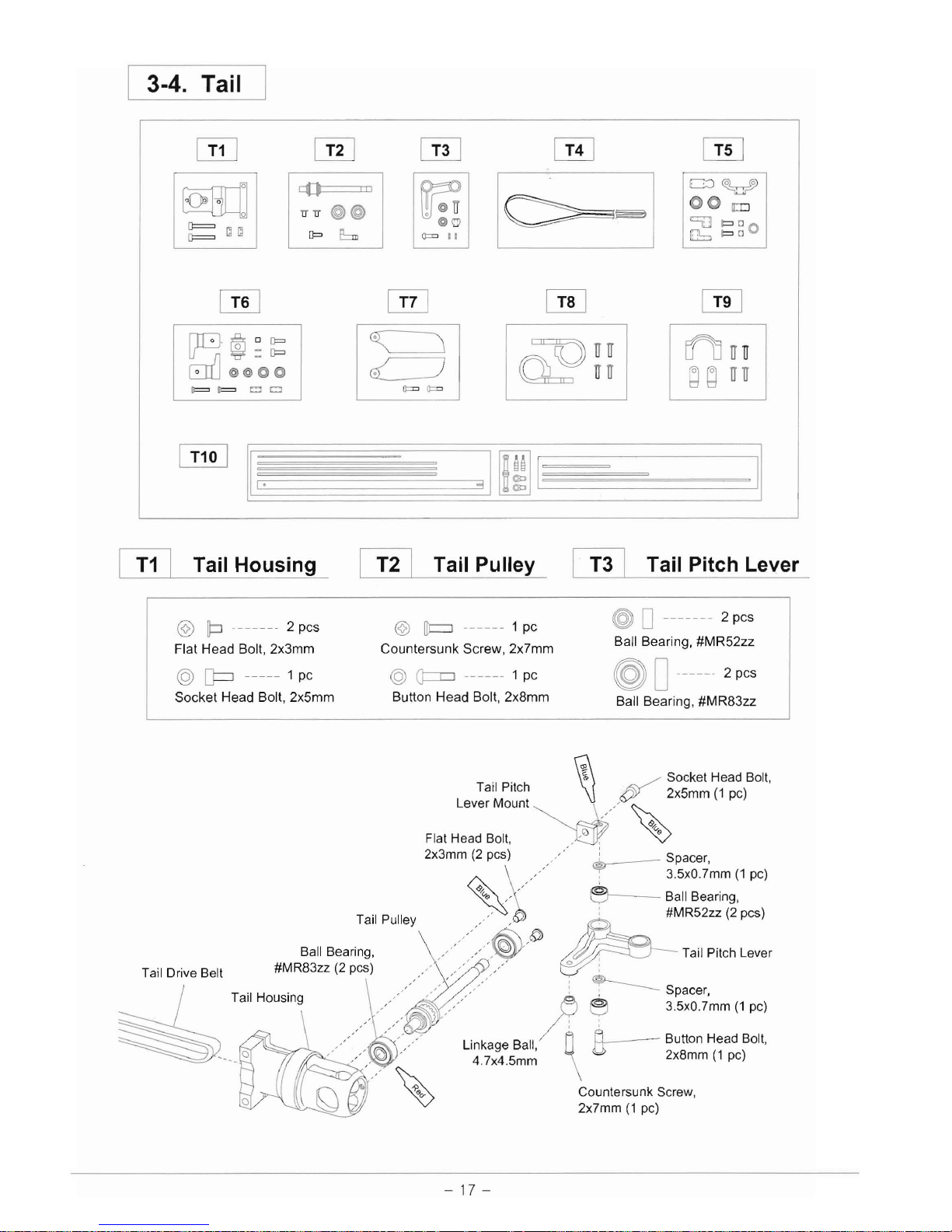
I 3-4. Tail
WJ
[ill
[ill [ill [ill
III
c:J~
c:()
00
a::o
lTlT
@@
~
~
@o
c:::u
I=>
0 0
[~~I
0==
~
~
[p
EJl::::,
I=>
0
=11
[ill
@]
[ill [ill
[Iq@oQ=
0==
o _
Q=
LflJuu
8{]
@@~@
~
19j
la~gl
d
~
uU
F=F=
00
==
[!ill
II,.
31ml
C!IJ
Tail Housing
~
Tail Pulley
~
Tail Pitch Lever
@ 0
.--.--.
2 pcs
@ p
------
2 pcs ©
[t::::J
-.----
1 pc Ball Bearing, #MR52zz
Flat Head Bolt, 2x3mm Countersunk Screw, 2x7mm
@
[J::=J
-----
1 pc @
Q=::o
------ 1 pc @ 0
------
2 pcs
Socket Head Bolt, 2x5mm Button Head Bolt, 2x8mm Ball Bearing, #MR83zz
m
~
Socket Head
Bolt,
Tail Pitch
\!
~
2x5mm
(1
pc)
Lever
Mount~,,-
~
~
~v.
Flat Head
Bolt,
,.0
, •
2x3mm
(2
pcs)
,":
Spacer,
,/
~
3.5xO.7mm(1
pc)
~,,-
e--
Tail Pulley
..
v~.':
: -
~~~~~~~~'
pes)
"~6i)
~
Ball Bearing,
,,-/
,
..
<~r
~
Tail Pitch Lever
83ZZ
(2
Pcs~)
\
A;----
~'s:~'imm
(1
po)
Tail
Drive Belt Tail
Ho::n:
/////
~
~
...
,,<'
.<,.",.
Linkage Ball,
0:
-
~
Button Head
Bolt,
~
--
__
()
,
,,-,~'
4
7x4
5mm
\ 2x8mm
(1
pc)
'-~
-.
Countersunk Screw,
2x7mm
(1
pc)
-
17-
II

~
Tail Pitch Plate, Tail Pitch Slider
@ p ---- 2 pcs
Flat
Head
Bolt,
2x6mm
~
0
------
2 pcs
Ball Bearing,
#MR74zz
& Caution
t:l
Apply just a little drop
of thread lock
to
the
I---
Tail Pitch
~
tip of the screw.
Make sure the Tail Plate ,,,"
",,"
)
~'
pitch link moves freely.
/,
T
'1
p't
hL' k
, ,
al
IC
In
Spacer Collar,
Spacer,
(ff;)~'
J)
fi
~
3x2.6mm
(2
pes)
6x0.4mm
(1
pc)
~
/~
~
Flat Head Bolt,
2x6mm
(2
pcs)
Ball Bearing,
~
""
#MR74zz
(2
pcs)
~
""
rA!1'
~
Tail Pitch Slider
~
""
~
Tail Slide Sleeve
[!!]
Tail Blade Holder
C!ZJ
Tail Rotor Blade
& Caution
Mind the direction
of the blade.
© [c::=J
-----
2 pcs
Countersunk
Screw,
2x10mm
@
[]:::::::J
------ 2 pcs
Socket
Head
Bolt,
2x6mm
@
Q=::r=J
------ 2 pcs
Bulton
Head
Bolt,
2x8mm
@ 0
----------
1 pc
Set
Screw,
3x3mm
@ 0
----------
2 pes
Ball Bearing,
#MR52zz
@ 0
---------
2 pcs
Ball Bearing,
#MR63zz
& Caution
Apply just a little drop
of thread lock to the
tip of the screw.
Make sure the Tail
pitch link moves freely.
Countersunk Screw,
-~
'R
2x10mm
(2
pes)
11
Spacer Collar,
,-----{j,
,
3,61mm(Z",,)
/M
o
'
v;
, /
~
Tail Rotor Blade
Socket Head Bolt,
2x6mm
(2
pes)
Ball Bearing,
#MR52zz
(2
pcs)
Button Head Bolt,
:
~
2x8mm
(2
pcs)
~
T,U
BI'd'
Hold"
-L
:
~
Ball Bearing,
~
#MR63zz
(2
pcs)
::
Tail Center Hub
3x3mm
(1
pc)
/'
Set Screw,
__
0
-
18-

~
Tail Servo Mount
~
Tail Fin Mount I T10 I Tail Boom
@
~
--------
8 pes @
[J:::::=J
------ 2 pes g
----
2 pes @
[J:::::=J
------ 2 pes
Self Tapping Screw, 2x7mm Socket Head Bolt, 2x13mm Socket Washer Socket Head Bolt, 2x8mm
2x7mm
(2
pes)
Tail Horizontal Fin \
Self Tapping Screw,
2,7mm
(4
p~)
\
~
~
--\
__
c?,~
Socket Head
Bolt,
2x13mm
(2
pes)
~
\
\i)
Self Tapping Screw,
2x7mm
(2
pes)
1 Tail Boom Brace,
Clockwise
\
Tail Boom,
Alumium
Caution
~
i,
<~~
Tail Fin Mount
Self Tapping Screw,
:~
, ,
~
i
Mind the direction
of the Tail Boom.
& Caution
Mind the direction
of the Tail Drive Belt.
Tail Brace Support
Tail Servo
Mount
Tail Drive Belt
Clockwise
3x263mm
K/~
/ •
0.,.
Micro, Mini servo type : 3x315mm
Tail Brace
Connector Standard servo type : 3x263mm
'*
CUlling
Tail Control
Rod
Socket Head Bolt,
2x8mm
(2
pes)
r--
--
Bali Link
(L),
\
13.5mm
(2
pes) Tail Control
Rod
End
-
19-
Table of contents
Popular Toy manuals by other brands


Topmodel CZ
Topmodel CZ MDM 1 FOX De-luxe quick guide

Accucraft
Accucraft Dora instruction manual

Babyhug
Babyhug Sporty Manual Ride-on user manual

Thames & Kosmos
Thames & Kosmos Ooze Labs 575004 Instructions for use

Multiplex
Multiplex FlightRecorder operating instructions

Eduard
Eduard Bismarck part 3 chain bar railings 1/200 quick start guide


