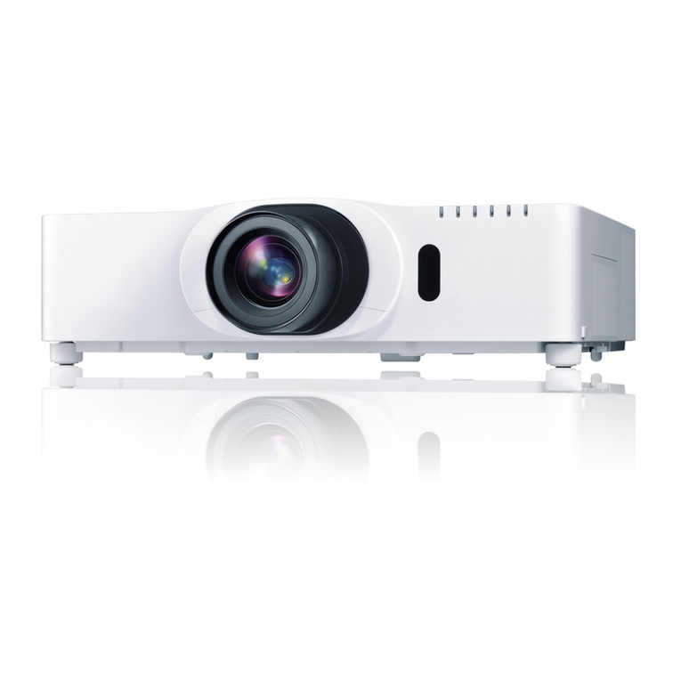
HDMI Sirius-PJ2 Quick start guide

Model Sirius-PJ2
Machine Codes:
Y076/Y077/Y078
Field Service Manual
June, 2015


Important Safety Notices
•RISK OF ELECTRIC SHOCK DO NOT OPEN
• TO REDUCE THE RISK OF ELECTRIC SHOCK, DO NOT REMOVE COVER. NO USER-
SERVICEABLE PARTS INSIDE. REFER SERVICING TO QUALIFIED SERVICE PERSONNEL.
This symbol warns the user that uninsulated voltage within the unit may have sufficient
magnitude to cause electric shock. Therefore, it is dangerous to make any kind of
contact with any part inside of this unit.
This symbol alerts the user that important literature concerning the operation and
maintenance of this unit has been included.
Therefore, it should be read carefully in order to avoid any problems.
• HEAT SINK MAY BE ENERGIZED. TEST BEFORE TOUCHING.
• The heat sink located on the power board is electrified. A mark is attached to the primary heat
sink. Pay attention to this area.
During servicing carefully observe the following.
1. OBSERVE ALL PRECAUTIONS
Items and locations that require special care during servicing, such as the cabinet, chassis, and
parts are labelled with individual safety instructions. Carefully comply with these instructions and all
precautions in the instruction manual.
2. BE CAREFUL OF ELECTRIC SHOCK
The chassis carries an AC voltage. If you touch the chassis while it is still live, you will get a severe
shock. If you think the chassis is live, use an isolating transformer or gloves, or pull out the plug
before replacing any parts.
3. USE SPECIFIED PARTS
The components have been chosen for minimum flammability and for specific levels of resistance
value and ability to withstand voltage. Replacement parts must match these original specifications.
Parts whose specifications are particularly vital to safe use and maintenance of the set are marked
on the circuit diagrams and parts list.
Substitution of these parts can be dangerous for you and the customer, so use only specified parts.
4. REMOUNT ALL PARTS AND RECONNECT ALL WIRES AS ORIGINALLY INSTALLED
For safety, insulating tape and tubes are used throughout, but some lift-off parts on the printed
wiring board require special attention.
1

All wires are positioned away from high-temperature and high-voltage parts, and, if removed for
servicing, they must be retuned precisely to their original positions.
5. LAMP
Be very careful of the lamp because it generates high heat while it is used at high voltage. When
replacing the bulb, make sure it is cool enough.
6. LENS
Do not look into the lens during projection. This is important to avoid damage to the eyes.
7. SERVICING
At the time of repair or inspection services, use an earth band (wrist band), without fail.
8. RUN A COMPLETE SAFETY CHECK AT THE COMPLETION OF SERVICING
After completion of servicing, confirm that all screws, parts, and wiring, removed or disconnected
for servicing, have been returned to their original positions. Also examine if the serviced sections
and peripheral areas have suffered from any damage as a result of servicing. In addition, check
the insulation between external metallic parts and the blades of wall outlet plugs. This examination
is indispensable in confirming complete establishment of safety.
Insulation check:
Pull out the plug from the wall outlet to disconnect the connection cable. Then turn on the POWER
switch. Use a 500V ohmmeter (Note 2) and make sure that the insulation resistance is 1M or
more between each terminal of the plug and exposed external metal (Note 1). If the measured
value is below the specified level, then it is necessary to inspect and fix the machine.
Note 1: Exposed external metal....RGB input terminals, control terminals, etc.
Note 2: If a 500V ohmmeter is not available for an unavoidable reason, then use a circuit tester or
the like for inspection.
2

Symbols, Abbreviations and Trademarks
This manual uses several symbols and abbreviations. The meaning of those symbols and abbreviations
are as follows:
Screw
Shoulder screw
Black screw (TCRU)
Connector
FFC (Flat Film Connector)
Harness clamp
Clip
E-ring
C-ring
Timing belt
Spring
SEF Short edge feed
LEF Long edge feed
[A] Short edge feed [SEF]
[B] Long edge feed [LEF]
3

Trademarks
HDMI and High-Definition Multimedia Interface are trademarks or registered trademarks of HDMI
Licensing, LLC.
Mac OS is a registered trademark of Apple Inc., registered in the U.S. and other countries.
PJLink trademark is a trademark applied for registration or is already registered in Japan, the United
States of America and other countries and areas.
VGA is a trademark of International Business Machines Corporation in the United States, other
countries, or both.
Crestron is a registered trademark of Crestron Electronics, Inc.
Microsoft®and Windows® are registered trademarks or trademarks of Microsoft Corporation in the
United States and /or other countries.
The proper names of the Windows operating systems are as follows:
The product names of Windows 7 are as follows:
• Microsoft® Windows® 7 Home Premium
• Microsoft® Windows® 7 Professional
• Microsoft® Windows® 7 Ultimate
• Microsoft® Windows® 7 Enterprise
Other product names used herein are for identification purposes only and might be trademarks of their
respective companies. We disclaim any and all rights to those marks.
4

TABLE OF CONTENTS
Important Safety Notices................................................................................................................................... 1
Symbols, Abbreviations and Trademarks.........................................................................................................3
Trademarks..................................................................................................................................................... 4
1. Product Information
Specifications....................................................................................................................................................11
Overview.......................................................................................................................................................... 12
Front and Top View......................................................................................................................................12
Rear View..................................................................................................................................................... 14
Control Panel/ Indicator.............................................................................................................................15
Names of the Terminals on the Rear Panel................................................................................................17
Part Names of the Remote Controller.........................................................................................................18
2. Installation
Installation Requirements................................................................................................................................. 23
Fire and Shock Precautions.........................................................................................................................23
Caution on Handling the Optional Lens.................................................................................................... 25
Lamp Replacement.......................................................................................................................................25
About High Altitude Mode..........................................................................................................................26
3. Replacement and Adjustment
Replaceable Part Hierarchy............................................................................................................................ 27
Special Tools.................................................................................................................................................... 28
Parts Replacement............................................................................................................................................31
Zoom Lens.................................................................................................................................................... 31
Lamp Unit......................................................................................................................................................31
Filters............................................................................................................................................................. 32
Top Cover.....................................................................................................................................................33
PCB Key-Pad................................................................................................................................................34
Front Cover...................................................................................................................................................35
PCB SCAP.....................................................................................................................................................36
PCB LED........................................................................................................................................................ 37
Lens Shift Dial............................................................................................................................................... 39
Rear Panel.................................................................................................................................................... 39
PCB Remote Controller................................................................................................................................40
USB Network Board....................................................................................................................................40
5

PCB Main Ass'y............................................................................................................................................41
PCB Network................................................................................................................................................43
PCB EX.......................................................................................................................................................... 43
Lamp Temp Sensor.......................................................................................................................................44
Exhaust Fan.................................................................................................................................................. 44
Speaker........................................................................................................................................................ 45
Lamp Fan (Upper)........................................................................................................................................46
Lamp Fan (Lower)........................................................................................................................................ 47
Reflector Fan.................................................................................................................................................48
G-LCD Fan....................................................................................................................................................49
R-LCD Fan.....................................................................................................................................................51
Internal Temp Sensor...................................................................................................................................53
B-LCD Fan.....................................................................................................................................................54
PS-Converter................................................................................................................................................ 55
Integrator 1...................................................................................................................................................57
Integrator 2...................................................................................................................................................57
IRIS Unit........................................................................................................................................................ 58
OPT Base...................................................................................................................................................... 59
Thermostat.................................................................................................................................................... 60
PCB Lamp Interlock......................................................................................................................................61
PSU Fan........................................................................................................................................................ 62
Power Supply-Ballast...................................................................................................................................64
Power Supply-DC........................................................................................................................................ 64
Replacement of Optical Parts..........................................................................................................................66
Polarizer-B....................................................................................................................................................66
Polarizer-G...................................................................................................................................................67
Polarizer-R.................................................................................................................................................... 67
Optical Parts Adjustment............................................................................................................................. 68
Adjusting and fixing parts...................................................................................................................68
Adjustment of the optical axis (Shadow adjustment)....................................................................... 69
Adjustment of the polarization plate (Contrast adjustment).............................................................76
Electrical Adjustment........................................................................................................................................ 80
6

Model-Specific Data Writing Procedure (When replacing of the PCB Main Ass’y on PJ WX6181N)...
.......................................................................................................................................................................81
Model-specific data writing procedure.............................................................................................81
Operation Procedure..........................................................................................................................81
Error Messages................................................................................................................................... 86
Procedure for rewriting EDID data............................................................................................................. 86
Outline software descriptions.............................................................................................................86
Equipment to be used and environment............................................................................................ 86
Software installation procedures....................................................................................................... 87
Rewrite procedure...............................................................................................................................87
Rewriting HDMI terminal EDID.......................................................................................................... 88
Rewriting D-SUB terminal EDID......................................................................................................... 91
Rewriting DP (Display Port) terminal EDID........................................................................................ 94
Miscellaneous......................................................................................................................................97
Procedure for writing of a serial number and a model number...............................................................99
Software installation............................................................................................................................99
Writing of a serial number and a model number............................................................................. 99
Data readout.....................................................................................................................................101
PC control software for service.................................................................................................................101
Outline software descriptions.......................................................................................................... 101
Equipment to be used and environment..........................................................................................102
Software installation procedures.....................................................................................................102
Repair and adjustment procedures................................................................................................. 102
Error messages..................................................................................................................................111
4. System Maintenance
Firmware Upgrade........................................................................................................................................ 113
Upgrading the firmware........................................................................................................................... 113
Functional Test................................................................................................................................................115
Analog RGB signal connection................................................................................................................ 115
Digital RGB signal connection..................................................................................................................116
Cautions when connecting an HDMI cable................................................................................... 117
Cautions when connecting a DisplayPort cable............................................................................ 118
Connecting an External Monitor..............................................................................................................120
7

Connecting the Blu-ray Player or Other AV Equipment................................................................ 121
Connecting Component Input.................................................................................................................. 123
Connecting HDMI Input............................................................................................................................124
Connecting to a Wired LAN.....................................................................................................................126
5. Troubleshooting
LED Display.................................................................................................................................................... 127
Indicator Messages...................................................................................................................................127
Power Indicator.................................................................................................................................127
Status Indicator................................................................................................................................. 127
Lamp Indicator.................................................................................................................................. 130
Temp. Indicator................................................................................................................................. 130
If the temperature protector is activated......................................................................................... 131
Service Mode.................................................................................................................................................132
Mode change............................................................................................................................................132
How to enter the Expert Mode........................................................................................................ 132
Additional functions...................................................................................................................................132
Menus and functions to be added by the Expert Mode................................................................132
Menus and functions to be added by the Service Mode..............................................................134
How to withdraw from the mode............................................................................................................. 137
Troubleshooting Guide..................................................................................................................................138
Operation Check for the Main Board..................................................................................................... 138
For Video....................................................................................................................................................139
For Audio................................................................................................................................................... 140
For Multi Media.........................................................................................................................................141
Operation Check for the PCB Network...................................................................................................141
Error Log......................................................................................................................................................... 142
Error Log Screen Image............................................................................................................................ 142
Displaying the error log screen....................................................................................................... 142
Service Information: Page-1............................................................................................................ 142
Service Information: Page-2............................................................................................................ 143
Service Information: Page-3............................................................................................................ 144
Service Information: Reset................................................................................................................144
Contents of Error Log (Page1) Display....................................................................................................145
8

Status Columns..................................................................................................................................145
PJ Usage Columns............................................................................................................................ 146
TEMP Columns..................................................................................................................................146
Other Columns..................................................................................................................................146
Contents of Error Log (Page2) Display....................................................................................................147
TEMP Columns..................................................................................................................................147
Lamp/Filter Clear Count..................................................................................................................148
Lamp ON/OFF Count..................................................................................................................... 148
Projector Hours Used........................................................................................................................148
Iris Current/Past................................................................................................................................148
Lamp Voltage: Indicated exceeding the Service Power................................................................148
Contents of Error Log (Page3) Display....................................................................................................149
Contents of Error Log (Reset) Display...................................................................................................... 150
ALL DATA...........................................................................................................................................150
9

10

Overview
Front and Top View
The lens is sold separately. The description below is for when the Standard Lens Type 1 lens is mounted.
No. Name
1 Indicator Section
2 Remote Sensor (located on the front and the rear)
3 Securing lever cover
4Lens Cap
(The optional lens is shipped with the lens cap.)
1. Product Information
12

No. Name
5 Lens
6 Focus Ring
7 Lens Release Button
8 Monaural Speaker (10 W)
9 Adjustable Tilt Foot
10 Security Bar
11 Controls
12 Lamp Cover
13 Exhaust vent
14 Zoom Lever/Zoom Ring
15 Lens Shift Dial (vertical/horizontal)
Overview
13

Rear View
No. Name
1 Remote Sensor (located on the front and the rear)
2 Exhaust vent
3 AC IN Terminal
4 Built-in Security Slot
5 Intake vent / Filter Cover
6 USB (LAN) Port (located inside the projector)
7 Terminals
1. Product Information
14

Control Panel/ Indicator
No. Name Function
1 POWER Indicator
When power is ON, the POWER indicator lights up in blue.
If the standby mode is set to "Normal" and the projector is in
standby mode, the POWER indicator lights up in red.
2 STATUS Indicator
If the standby mode is set to "Normal" and the projector is in
standby mode, the STATUS indicator is OFF.
The indicator lights up or flashes when the button has been
pressed while the projector is in key lock mode or the
projector has a problem.
3 LAMP Indicator Indicates the lamp status and replacement grace period.
4 TEMP. Indicator Lights up in orange when the surrounding temperature is
high.
5 Power Button
Turns the projector on and then off (standby).
To turn the projector off (standby), then press the Power
button one time. When the confirmation message appears
on the screen, press the Power button again.
6 AUTO ADJ. Button Auto adjustment for Computer (Analog RGB), HDMI 1,
HDMI 2, DisplayPort projecting.
Overview
15

No. Name Function
7 EXIT Button
Returns to the previous hierarchical menu in the currently
displayed on-screen menu. When the cursor is placed over
the main menu, the menu closes. When a confirmation
message appears, the operation is canceled.
8 / Volume Buttons
• While an on-screen menu is displayed, use the , , ,
and buttons to select the item to set or adjust.
• If no on-screen menu is displayed, use the and
buttons to adjust the volume.
9 ENTER Button
Proceeds to the next hierarchical menu in the currently
displayed on-screen menu.
Applies the selected item while the confirmation message is
displayed.
10 MENU Button Displays an on-screen menu for setting or adjusting a variety
of items.
11 INPUT Button
Selects the signal input.
Pressing the INPUT button briefly displays the "INPUT"
screen.
Pressing the INPUT button for one second or longer checks
the signal inputs automatically in the following order: HDMI
1 HDMI 2 DisplayPort BNC BNC(CV)
BNC(Y/C) COMPUTER USB-A. When the projector
detects a signal input, it projects the input signal.
12 Geometric. Button
Displays the “GEOMETRIC CORRECTION” screen of the
on-screen menu. Corrects horizontal and vertical keystone
distortions.
1. Product Information
16

Names of the Terminals on the Rear Panel
No. Name
1 HDMI OUT Connector (Type A)
2 HDMI 1 IN Connector (Type A)
3 HDMI 2 IN Connector (Type A)
4 DisplayPort IN Connector
5 BNC Input Connectors (BNC × 5)
6 COMPUTER IN/ Component Input Connector (Mini D-Sub 15 Pin)
7 COMPUTER AUDIO IN Mini Jack (Stereo Mini)
8 BNC AUDIO IN Mini Jack (Stereo Mini)
9 REMOTE Connector (Stereo Mini) (not available on this series of projectors)
10 PC CONTROL Port (D-Sub 9 Pin)
11 BNC (Y/C) Input Connector (BNC × 2)
12 BNC (CV) Input Connector (BNC × 1)
13 3D SYNC Connector (Mini DIN 4 Pin)
14 AUDIO OUT Mini Jack (Stereo Mini)
15 USB-A Port (Type A)
Overview
17

No. Name
16 Ethernet Port (RJ-45)
Part Names of the Remote Controller
1. Product Information
18
Table of contents


