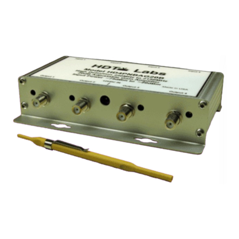
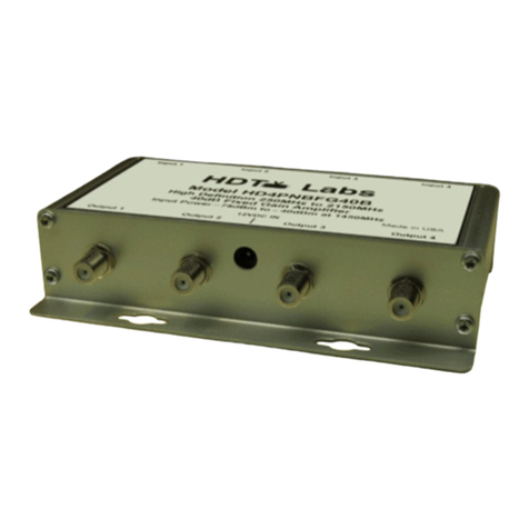
HDTV Labs HD4PNBFG20B User manual

20 dB Fixed Gain 4-Port Amplifier
Model HD4PNBFG20B
Instruction Manual
www.hdtvlabs.tv

Model HD4PNBFG20B
High Definition 250MHz to 2150MHz
20dB Fixed Gain Amplifier
Connection Instructions
Caution: Ensure all cables and connectors have no short circuits. Make all cable connections before
energizing the power supply connection or damage to the unit could occur.
1. Using High Definition RG-6 coaxial cable for all connections, attach amplifier inputs and outputs to
corresponding devices.
2. Connect the external power supply to the amplifier "12VDC" jack.
3. Built-in DC blocking capacitors eliminate the need for any external capacitors.
4. The input signal level to this amplifier is only -75 dBm as compared to a typical -35 or -40 dBm level
for existing amplifiers. With the exceptionally wide signal level input range of -75dBm to -20dBm,
installers can connect very weak input signals as well as having a much lower risk of overdriving the
amplifier.
5. If poor C/N ratio is seen at the output of the amplifier, it is being overdriven and the installer must
reduce the input power for it to work correctly. Proper output signal should be checked with a meter
to prevent overdriving any of the system's four channels.
6. Check our website at www.hdtvlabs.tv for the latest instruction manual updates. This is
HD4PNBFG20B Rev. 1.1

Model HD4PNBFG20B
High Definition 250MHz to 2150MHz
20dB Fixed Gain Amplifier
Description
The HD4PNBFG20B is a Professional-Grade 4-channel 20dB fixed gain amplifier designed to
recover low-level signals that may be well below the threshold of most satellite power meters.
Each channel has a fixed gain in excess of 20dB with 6dB slope compensation and covers a
frequency range of 250MHz to 2150MHz. The HD4PNBFG20B is used in conjunction with
stacked, multiswitch, and head-end systems to overcome cable, splitter, tap, and other system
losses. The inputs and outputs of each of the four amplifier channels have internal DC blocking
capacitors, thus eliminating the need to add external DC blocking capacitors. MADE IN USA
Features:
Wide signal dynamic range capability
Ultra-low level signal recovery
Corrosion-resistant connectors
Rugged aluminum construction
Specification Minimum Typical Maximum
Frequency…………………………………………. 250MHz 2150MHz
Noise Figure…………...………………………….. 4.0dB 5.5dB
Absolute Maximum Total Input Power1………….. 0dBm
Input Power Range……..…………………………. -75dBm2-20dBm3
Individual Transponder Output Power……………. 0dBm
Gain
at 250MHz..…………………………... 14.5dB 15.5dB 16.5dB
at 750MHz..…………………………... 17.5dB 18.5dB 19.5dB
at 950MHz……………………………. 18.0dB 19.0dB 20.0dB
at 1450MHz…………………………... 20.0dB 21.0dB 22.0dB
at 1650MHz..…………………………. 20.5dB 21.5dB 22.5dB
at 2150MHz…………………………... 20.5dB 21.5dB 22.5dB
Channel-to-Channel Isolation4……………………. 45dB

Specification Minimum Typical Maximum
Input Return Loss
at 250MHz……………………………. 11dB
at 950MHz……………………………. 20dB
at 1450MHz…………………………... 20dB
at 2150MHz…………………………... 11dB
Output Return Loss
at 250MHz……………………………. 15dB
at 950MHz……………………………. 18dB
at 1450MHz…………………………... 20dB
at 2150MHz…………………………... 11dB
1dB Input Gain Compression Point5
at 250MHz…………………………….. -3dBm
at 950MHz…………………………….. -3dBm
at 1450MHz…………………………… -3dBm
at 2150MHz………..………………….. -5dBm
Input Signal Power for 3rd Order Intermod Rejection Ratio of 40dB6
at 250MHz…………………………….. -7dBm
at 950MHz…………………………….. -10dBm
at 1450MHz…………………………… -12dBm
at 2150MHz………..………………….. -15dBm
DC Supply Voltage ………………………………. 12VDC
DC Supply Current………………………………... 650mA
For Indoor Use Only. The HD4PNBFG20B is supplied with an external 12VDC power supply.
Operating temperature of the HD4PNBFG20B is –40 C to +85 C. The mechanical dimensions are
6.4”W 4.4”L 1.5”H
(Specifications subject to change without notice.)
Notes:
1. Absolute Maximum Power is the total power that arrives at the amplifier input from 250MHz to 2150MHz. Satellite power
meters typically read the power level of a single transponder at a time. If all transponders are active from 250MHz to
2150MHz and the power of all transponders are equal, then total available input power across the 250MHz to 2150MHz
bandwidth is approximated by taking the satellite power meter reading at 1450MHz and adding 20dB. Make sure not to
exceed -20dBm as measured with a satellite power meter at 1450MHz.
2. The –75dBm level assumes that the overall system noise figure is not too high such that the carrier-to-noise ratio of the
satellite signal has not been degraded such that signal recovery is not possible. Signal levels lower than –75dBm can be
recovered with properly designed systems having over-all low system noise figures. Low noise figure systems are
achieved by avoiding the addition of too many attenuators or too much loss in front of an amplifier block. It is always
better to add loss after an amplifier to minimize system noise figure as long as the signal at the amplifier input does not
over-drive that amplifier.
3. Assumes maximum power levels as measured with a satellite power meter and all transponder signals active from
250MHz to 2150MHz. (See note 1) A frequency response loss slope of 6dB is assumed, i.e. transponder power measured
at 250MHz with a satellite power meter is 6dB higher than power measured at 2150MHz due to cable loss versus
frequency characteristics. If transponder power levels are equal, limit the maximum power to –20dBm at all frequencies.
An easy method to determine if the amplifier is being over-driven is to connect a satellite power meter to the output of the
amplifier and check C/N, BER, and IRD performance. If acceptable transponder power levels are measured but low C/N
values, high BER values, and low IRD levels are measured, reduce the input level into the amplifier until good C/N, BER,
and IRD results are measured.
4. Channel-to-Channel Isolation is measured referenced to the output of each amplifier. Channel-to-Channel Isolation has a
typical value of 35dB at 2150MHz.
5. Measured using a single CW signal. No transponder signals present.
6. Measured using two CW signals with 1MHz spacing. No transponder signals present.
Copyright © 2010 HDTV Labs, All Rights Reserved. HD4PNBFG20B Manual Version: Rev. 1.1
Table of contents
Other HDTV Labs Amplifier manuals
