True Systems pT2-500D User manual
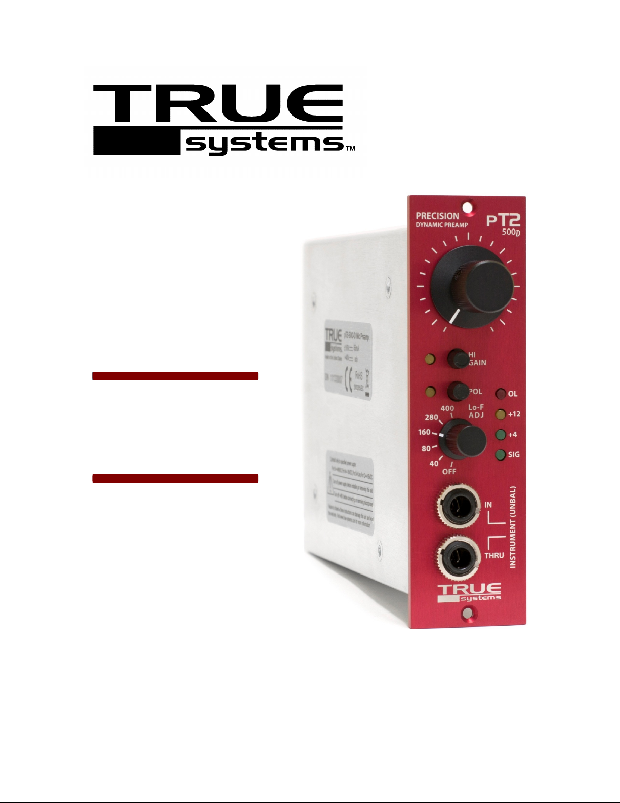
pT2-500D
PRECISION
DYNAMIC MICROPHONE
PREAMPLIFIER
with Direct Input and
Low-Frequency Adjust Control
500 series compatible module
OPERATION MANUAL
Version 1.0

pT2-500D Microphone Preamplifier OPERATION MANUAL
Version 1.0
2
©2011 TRUE Y TEM
CERTIFICATION
Declaration of Conformity
Sunrise Engineering and Design Inc. hereby declares the True ystems pT2-500D
single channel microphone preamplifier module to be in material conformity with the
following EC directives and related standards:
•2006/95/EC Low Voltage Directive
•2004/108/EC EMC Directive
•EN60065: 1998 Safety requirements for audio equipment
•EN55103-1: 1997 Electromagnetic compatibility of audio equipment: Emission
•EN55103-2: 1997 Electromagnetic compatibility of audio equipment: Immunity
Technical files are maintained at corporate headquarters of Sunrise Engineering and
Design Inc., 1630 S. Research Loop, Suite 150, Tucson, Arizona 85710, U.S.A
RoHS
Certificate of Compliance
This is to certify that the True ystems pT2-500D is RoHS compliant and meet the
requirements and specified limits of restricted substances according 2002/95/EC
directive.
WEEE
pT2-500D is marked with the WEEE symbol to comply with the European Union’s
Waste Electrical & Electronic Equipment (WEEE) Directive 2002/96/EC. The symbol
indicates that this product should not be treated as household waste. It must be
disposed and recycled separately as electronic waste. Please assist to keep our
environment clean.
Above declarations are void by modification of the device without approval,or unau-
thorized servicing.
Tucson, 09-01-2011
Tim Spencer, president

pT2-500D Microphone Preamplifier OPERATION MANUAL
Version 1.0
3
©2011 TRUE Y TEM
SAFETY & OPERATING PRECAUTIONS
Important symbols:
This symbol appearing on the product or in this manual indicates the
presence of dangerous voltage within the product enclosure that presents
the risk of electric shock injury. When this symbol appears next to an
operation discussed in this manual, only qualified technical personnel should
perform that operation.
This symbol indicates important operating or maintenance instructions that
should be read carefully. Failure to observe these instructions could result in
damage to this product or other equipment.
WARNINGS:
While no hazardous voltage is present within this product during normal
operation, please observe the following warnings regarding any AC-powered
equipment into which this product is installed:
•To reduce the risk of electric shock injury, do not remove the access
covers on AC-powered equipment. Refer servicing to qualified personnel.
•This unit is intended for indoor operation only
•Do not operate this unit in the presence of rain, liquids or condensing
moisture.
•Do not expose the unit to dripping or splashing liquids.
•Do not place liquid-filled objects on the unit.
•Do not defeat the earth ground connection in the AC power cable.
•Do not defeat intended AC power connection polarization.
•Do not use a damaged or excessively worn cord to connect the equipment
to AC power.
CAUTIONS:
•Severe damage to pT2-500D will occur if incorrect power supply
voltages are applied to the card edge connector. Please consult the
“CONNECTIONS” section in this manual for proper power supply
specifications/connections.
Disclaimer:
Product failure caused by improper voltage application cannot be
covered under warranty.
•Liquid entering the product enclosure is likely to cause performance
degradation or failure. Failures due to moisture entering the enclosure
cannot be covered under warranty. Should liquid spill on the unit,
immediately disconnect it from the AC power source and contact TRUE
ystems for servicing instructions
•This product is designed to operate in an ambient temperature range of
10°C to 50°C (50°F to 122°F).

pT2-500D Microphone Preamplifier OPERATION MANUAL
Version 1.0
4
©2011 TRUE Y TEM
CONTENTS
CERTIFICATIONS…………………………………………………………...
CE
RoHS
WEEE
2
SAFETY and OPERATING PRECAUTIONS…………………………….
3
TABLE of CONTENTS……………………………………………………...
4
PRODUCT OVERVIEW……………………………………………………..
New Type 2 Circuit Design
Features
5
INSTALLATION……………………………………………………………...
Unpacking
Card Rack Installation
Card Edge Connections
Ventilation
6
OPERATION………………………………………………………………….
Connections
Output
Microphone Input
Instrument Input and Thru (DI)…………………………………………………..
A Word About Cables……………………………………………………………………
Cable Types
Instrument cables
Microphone and Line Level cables
Front Panel Layout……………………………………………………………………….
Controls
Gain, LO/HI
Low Frequency Adjust
Phantom Power
Instrument Input
Level Indicators
7
8
9
10
SPECIFICATIONS…………………………………………………………...
11
TROUBLESHOOTING………………………………………………………
12
13
WARRANTY & SERVICE INFORMATION……………………………..
Registration and Warranty
Service and Support……………………………………………………………………..
14
15

pT2-500D Microphone Preamplifier OPERATION MANUAL
Version 1.0
5
©2011 TRUE Y TEM
PRODUCT OVERVIEW
Thanks for using our product! We appreciate the confidence you place in TRUE
ystems by purchasing the
pT2-500D
microphone preamplifier/instrument DI. We
design our products to deliver stunning musical accuracy, uniquely useful features,
exceptional value, and reliability. Every aspect of this product design was determined by
careful listening tests and extensive user feedback. Please feel free to contact us with
questions or comments.
The
pT2-500D
utilizes our Type 2 design to achieve ultra-resolution musicality and
provide optimum performance with dynamic mics, ribbon mics, and self-powered tube
mics. We’ve eliminated the components required for phantom power in order to provide
higher input impedance and reduced distortion and noise. More preamp gain is typically
required by dynamic and ribbon microphones, so we’ve provided up to 76dB – in two
ranges selected for easy control.
Lo-F Adjust (low frequency adjustment control):
The Lo-F Adjust selector allows nuanced attenuation of low-end signal content. The five
frequency selections are reciprocal to proximity effect characteristics of various
commonly-used microphone types, and can be particularly effective in removing low
frequency “mud“ from vocals and bass instruments.
FEATURES
API™ 500 series module format
Totally Balanced Topology for:
•insensitivity to ground noise/loops
•Insensitivity to EMI, both external and from adjacent modules/power supplies
•reduced distortion
Rail-to-Rail design for:
•higher internal headroom
•higher maximum input level without pad (up to +21dBu)
•higher output level without transformer and excessive power supply current
0.1% precision resistors for:
•exceptional Common-Mode and Output Signal Balance performance
•excellent unit-to-unit sonic consistency
“Real DI” IN and THRU jacks for:
•Easy hookup to amps for simultaneous DI and amp’d tracking or live sound
•Easy hookup to other DI’s or effects for simultaneous tracking or live sound
Detented, continuous Gain Control and Dual Gain Ranges for:
•easy gain resetability
•easy gain setting over wide gain ranges
Steel Enclosure for:
•protection from EMI and RFI
•protection from ESD and handling contamination/damage
Lo-F Adjust control
4-Level Signal Meter

pT2-500D Microphone Preamplifier OPERATION MANUAL
Version 1.0
6
©2011 TRUE Y TEM
INSTALLATION
Unpacking
Please read and follow instructions on the Caution sticker on the anti-static bag
enclosing the pT2-500D:
•Please ground yourself to dissipate static electricity before opening anti-static bag
and handling the pT2-500D.
•Save the anti-static bag, carton, and foam supports for future storage or ship-
ment.
Card Rack Installation
1. Turn off card rack AC power and remove AC power cord.
2. Carefully align the pT2-500D with the desired card slot edge connector. This is a
blind installation, so take your time in order to avoid scratching this unit or adjacent
units in the card rack.
3. Press the unit firmly and evenly until you feel it seat in the card edge connector.
4. If you have difficulty inserting this unit, check for debris in the card rack edge
connector. It may help to rearrange adjacent modules in the card rack.
5. Secure the front panel with two 4-40 flat head philips mounting screws (supplied with
API™ card racks and Lunchbox™).
6. Reconnect the AC power cord and turn on the rack power.
Card Edge Connections
Note:
Disclaimer:
If you are using a custom card rack, or a
card rack not manufactured by API™, please
verify the following power supply
terminations:
Pin 12 = +16VDC
Pin 13 = Power Common
Pin 14 = -16VDC
Pin 1 is located at the top of the card edge
connector.
Damage caused by incorrect power
supply termination or voltage cannot be
covered under warranty.
Ventilation
We recommend that the card rack containing the pT2-500D have adequate ventilation
to maintain the unit within an operating ambient temperature range of 10°C to 50°C
(50°F to 122°F).
15 +48VDC
14
13
12
11
10
9
8
7
6
5
4
3
2
1
-16VDC
POWER COMMON
+16VDC
NC
+INPUT
NC
-INPUT
NC
NC
AUDIO COMMON
-OUTPUT
NC
+OUTPUT
CHASSIS GROUND
pT2-500D Microphone Preamplifier OPERATION MANUAL
Version 1.0
7
©2011 TRUE Y TEM
OPERATION
Connections
Read “Safety and Operating Precautions”on page 3, and “Installation” on page 6 of
this manual before making any connections to the pT2-500D.
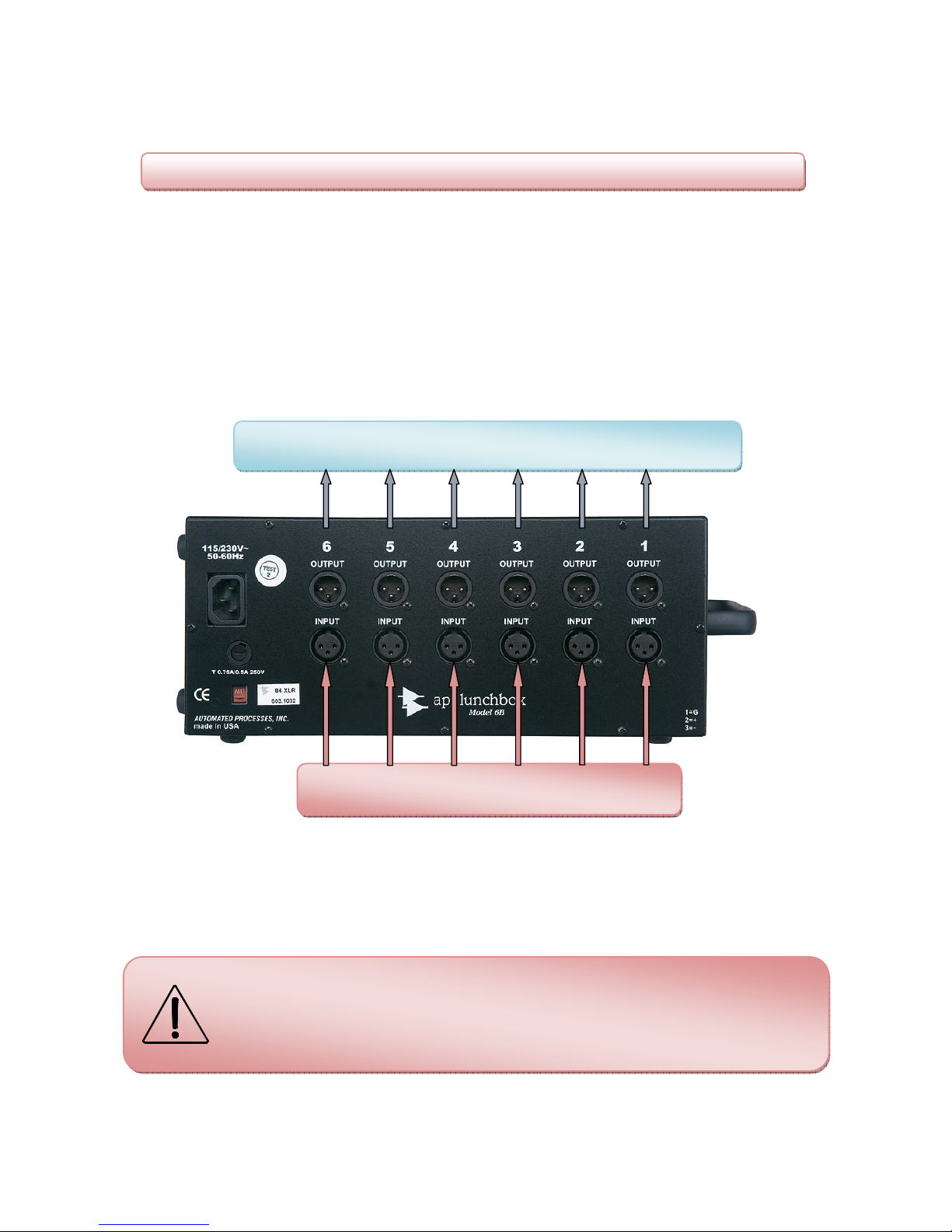
1. Connect output signal cables from the XLR OUTPUT connectors on your 500-series
compatible card rack to the analog line-level inputs of your DAW, recorder, mixer,
A/D converter, signal processor, etc.
XLR outputs used with unbalanced cable configuration must be wired correctly.
See page 9 “Output Cable Connection – unbalanced”.
DAW, Recorder, Mixer, A/D Converter, Signal Processor, etc.
Microphones
(for card slots with Mic Preamps installed)
2. Connect microphone cables to the XLR INPUT connectors on card slots that contain
your pT2-500D or other mic preamp.
Do not attempt to connect unbalanced microphones to the pT2-500D
It is not intended to operate with this type of microphone.
NOTE: The input and output connector locations on some 500-series
compatible card racks are different than on API™ units. In order to prevent
time-consuming errors and possible damage to your equipment, please
consult the manufacturer’s documentation for the particular card rack you are
using.

pT2-500D Microphone Preamplifier OPERATION MANUAL
Version 1.0
8
©2011 TRUE Y TEM
Instrument Input and Thru (DI)
1. Connect your instrument cable to IN. This interrupts the microphone input on the rear
panel and routes your instrument to the discrete FET DI in the pT2-500D. This
input is intended for unbalanced signal sources.
DO NOT use TRS plugs for this input or the DI will not be activated
2. If desired, connect a cable from THRU to a guitar/bass amp, another DI, or additional
signal processing device.
3. The IN and THRU jacks are directly connected as in any typical standalone DI. Since
the input impedance of the pT2-500D FET DI is 2.5 Megohms, it does not provide
any significant electronic load to the instrument pickup. When connection is made via
the THRU jack to an amp or other device, the input impedance of that device will
essentially determine the electronic load on the instrument pickup. Keep in mind that
lower impedance may alter the tonal character of your instrument.

pT2-500D Microphone Preamplifier OPERATION MANUAL
Version 1.0
9
©2011 TRUE Y TEM
A Word About Cables…
Most users of the pT2-500D have invested much time and money in their selection of
microphones and preamplifiers. We recommend that you give some consideration to the
microphone, instrument and output cables you select, as well.
•Use high-quality, low capacitance cable. Braided shielding and “star quad” type mic
cables will perform better in electrically noisy environments. Manufacturers such as
Canare, Mogami(and others) make high performance cable of this type.
•Some “house brand” cables are made by quality manufacturers, but others can be
inferior. Be careful. Use cables with high-quality connectors (Neutrik, Switchcraft,
etc.).
•Our studio testing has shown that some of the more esoteric guitar/instrument
“super-cables” do, indeed, sound better. Noticeable improvement, but at a stiff price.
Try before you buy!
•Avoid excessive cable length.
•Replace damaged connectors.
Cable Types
There are two styles of audio cables used for connections to the pT2-500D in a 500-
series rack:
•Shielded / single-conductor type for unbalanced signals (Instrument cables)
•Shielded / twisted-pair type for balanced signals ( Microphone / Line level cables)
We recommend that all interconnecting cables are wired according to the following
standards. Failure to do this can result in malfunction or audible distortion.
For Instrument cables (unbalanced)
on TS connectors:
•Tip = positive (+) signal
•Sleeve = shield
tip
sleeve
TS connector (¼” plug, mono)
For Microphone and Line level cables (balanced)
on XLR connectors:
•Pin 1 = shield
•Pin 2 = positive (+) signal
•Pin 3 = negative (-) signal
female male
XLR connector (front side)
Output cable connection – unbalanced
NOTE: When connecting an XLR output from pT2-500D to a subsequent
audio device with an unbalanced input, the negative signal lead (from Pin 3)
must be wired to shield (Sleeve) at the TS connector. For this type of
connection, the Maximum Output Level is reduced to +23dBu.
pT2-500D Microphone Preamplifier OPERATION MANUAL
Version 1.0
10
©2011 TRUE Y TEM
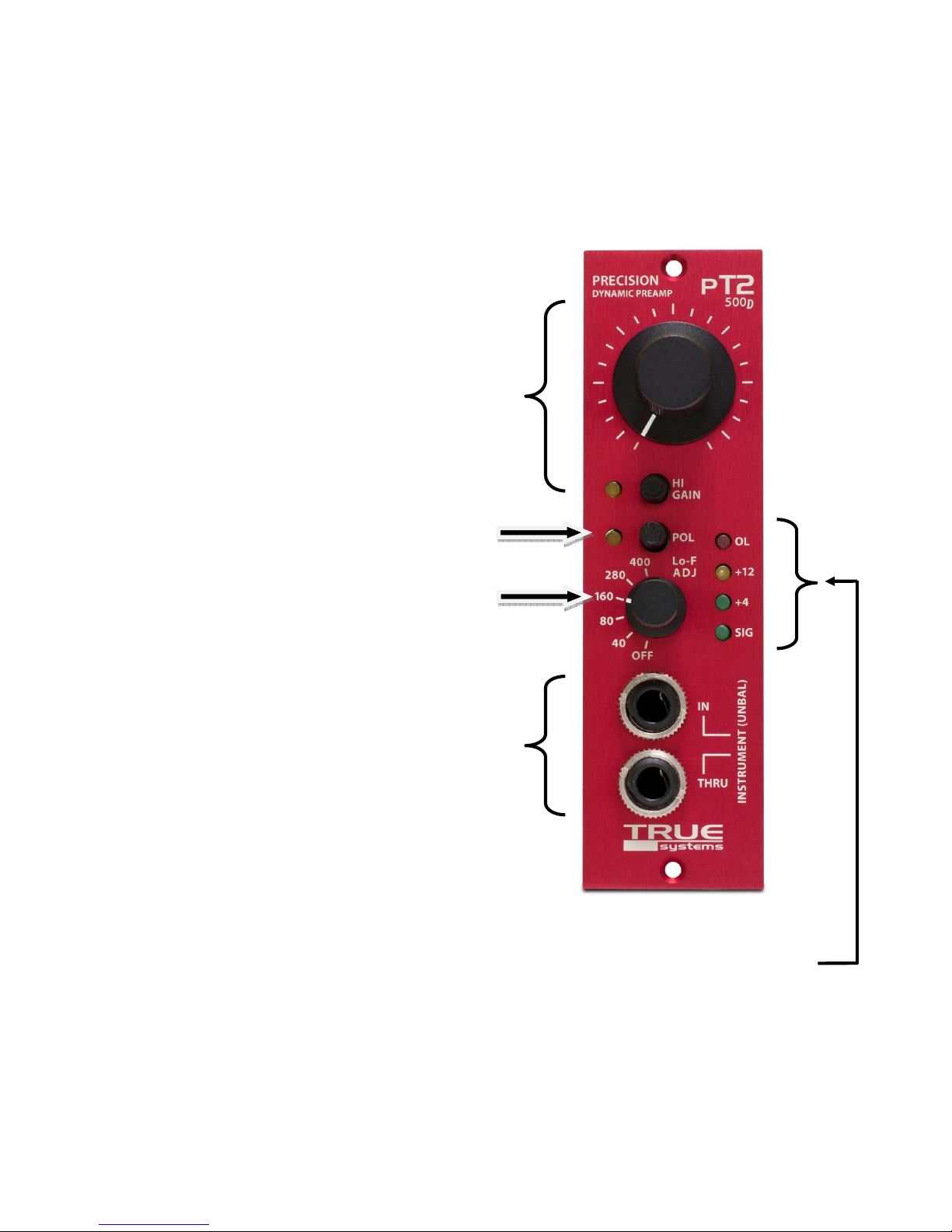
Front Panel Layout
CONTROLS
Gain
The detented rotary gain control along with the
HI GAIN button setting determines the overall
gain through the preamp. When HI GAIN is off,
the rotary gain control range is from 6.5dB to
60dB and maximum input level is
approximately +21dBu. When HI GAIN is on,
the rotary gain control range is from 24dB to
76dB with maximum input of +10dBu.
Polarity
Output signal polarity is reversed when the
POL button is depressed.
Low Frequency Adjust
The Lo-F ADJ switch activates a -6dB per
octave filter at the selected frequency.
CONNECTIONS
Instrument Input
Discrete FET Instrument Direct IN. Connect
your instrument cable to the IN jack
(unbalanced instrument cable only). If desired,
connect a cable from THRU to a guitar/bass
amp, another DI, or additional signal
processing device. See previous section for
details.
LEVEL INDICATORS
The level indicators show output signal level. SIG illuminates at -24dBu and indicates
that a signal is present on the channel. +4 illuminates when the output signal reaches
normal operating level of +4 dBu. +12 illuminates when the output signal reaches
+12dBu. OL illuminates when the output signal level exceeds +26dBu which is 3dB
below actual preamp overload.

pT2-500D Microphone Preamplifier OPERATION MANUAL
Version 1.0
11
©2011 TRUE Y TEM
SPECIFICATIONS*
Frequency Response
@ 40dB gain (-3 dB) 1.5 Hz – 550 kHz
THD+N
@ 40dB gain,+26 dBu out, 20Hz to 20kHz BW 0.0004%
Intermodulation Distortion
SMPTE/DIN 4:1 (60Hz/7kHz), @40dB, +26dBu
0.0009%
Noise (E.I.N)
Rs = 0 Ohms -133 dB
CMRR
@40dB gain, Vcm = +10dBu 85 dB
Slew Rate 50 V/us
Microphone Input 1x balanced (XLR-type)
(via card edge connector)
Maximum Input Level + 21 dBu
Input Impedance 10 kOhm
Gain +6.5 to +60 dB (LO gain)
+24 to +76 dB (HI gain)
Low Frequency Filter Selection (-6dB/Oct) Off, 40, 80, 160, 280, 400Hz
Instrument Input (DI)
FET discrete circuit
1x unbalanced, (TS jack)
(IN jack on front panel)
Maximum Input Level (DI) +11 dBu
Input Impedance (DI) 2.5 MOhm
Gain (DI) -10 to +43.5 dB (LO gain)
6.5 to +60 dB (HI gain)
Output 1x balanced (XLR)
(via card edge connector)
1x unbalanced (TS jack)
(THRU jack on front panel)
Output Impedance 100 Ohm (50 X 2)
Maximum Output Level
+29 dBU
Power Requirements ±16 VDC
(power supply - 500 format rack)
(via card edge connector)
Power Consumption 65 mA = 1.04 W (±16V)
Dimensions
1.5“ x 5.25“ x 6.05“ (W x H x D)
38.1 x 133.4 x 153.8 mm
Weight
1.4 lbs. (0.64 Kg)
*Typical performance. Specifications subject to change without notice.

pT2-500D Microphone Preamplifier OPERATION MANUAL
Version 1.0
12
©2011 TRUE Y TEM
TROUBLESHOOTING
Symptom Solution
No signal output. Main power switch
on rack power supply is ON, but no
LED’s illuminate on pT2-500D.
•Check AC power source and cord connection
•Check fuse on rack power supply.
•Check that preamp card edge connector is
properly seated.
No signal output. Main power switch
on rack power supply is ON and
appropriate LED’s illuminate on
pT2-500D.
•Check status of phantom power.
•Check continuity of mic and electric
instrument cables.
•Check continuity of output cables.
•Make sure GAIN control is adjusted.
Output signal is distorted. Outputs
are connected for balanced
operation.
•Make sure GAIN is adjusted so that the OL
indicator does not activate during the audio
program.
•Make sure the high output capability of this
unit is not overloading the device or
monitoring system to which it is connected.
•Check continuity of output cable.
•Make sure outputs are not connected to a
load impedance of less than 600 ohms.
Output signal is distorted. Outputs
are connected for unbalanced
operations.
•Make sure the minus (-) output signal pins
are connected to the shield and not left
unconnected. See “Output Cable
Connection” section, page 9.
•Check troubleshooting tips for balanced
operation (above).
Hum can be heard in the audio
program.
•Check continuity of output cables
(particularly shields).
•Alternatively, disconnect shields on one end
of output cables (not appropriate for
unbalanced connections).
Electric instrument connected to a
Direct Input does not produce a
signal or signal is distorted.
•Check continuity of electric instrument
cables.
•Check the batteries or AC power source of
any “foot pedal” effects processors
connected to the Direct Input.
•Make sure that the instrument cables have

pT2-500D Microphone Preamplifier OPERATION MANUAL
Version 1.0
13
©2011 TRUE Y TEM
Symptom Solution
standard tip-sleeve ¼” phone plugs.
DO NOT use TRS plugs!
Radio Frequency Interference can
be heard in the audio program
(swishing sound or audio from a
radio transmitter)
•Make sure that mic cables are of good
quality and that the shield is properly
connected. Avoid excessive length.
•Make sure that earth ground connection is
maintained via the AC power cord.
DO NOT use an isolator!
•Make sure the unit is located away from
known sources of radio frequency energy.
(e.g. cell phone, walky-talky etc.)

pT2-500D Microphone Preamplifier OPERATION MANUAL
Version 1.0
14
©2011 TRUE Y TEM
WARRANTY & SERVICE INFORM
ATION
REGISTRATION
Don’t forget to register your pT2-500D by completing the registration form online at our
website www.synthax.de (Support / Product Registration). Alternatively, fill out the
enclosed Registration Card and return it to us. This allows Synthax GmbH to contact you
regarding any updates, upgrades or applications information that may become available.
WARRANTY
Synthax GmbH warrants the TRUE systems pT2-500D to be free from defects in
material and manufacture, when properly installed and used according to instructions in
the Operation Manual, for a period of two years from the date of sale to the original
purchaser. Units returned for warranty repair to Synthax GmbH or an authorized TRUE
ystems repair facility will be repaired or replaced at the manufacturer’s option, free of
charge. Supplementary shipping charges will apply to units returned to addresses
outside the continental USA. All units returned to Synthax GmbH or authorized TRUE
systems repair facility must be prepaid, insured and properly packaged. Purchaser
must obtain a Return Authorization (RA) number from Synthax GmbH prior to returning a
product. Synthax GmbH may require proof of the purchase date in the form of a copy of
a dated original retail invoice.
This warranty is void if, in the sole judgment of Synthax GmbH, the product has been
abused, neglected, misapplied, or has been damaged by an accident, modification, or
attempted repair by unauthorized personnel. This warranty will not apply to cosmetic
damage incurred due to normal handling and use. Synthax GmbH reserves the right to
change or improve the product design at any time without prior notice. Incorporation of
design changes in future versions of the product does not imply the availability of
upgrades for existing units.
This warranty is in lieu of all other warranties, expressed or implied, and Synthax GmbH
specifically disclaims all implied warranties, including, but not limited to, warranties of
merchantability and fitness for a particular purpose. The purchaser acknowledges and
agrees that in no event shall Synthax GmbH be held liable for any special, indirect,
incidental or consequential damage, or for injury, loss or damage sustained by any
person or property, that may result from the use of, or failure of this product to operate
correctly at any time.

pT2-500D Microphone Preamplifier OPERATION MANUAL
Version 1.0
15
©2011 TRUE Y TEM
SERVICE and SUPPORT
Other than cleaning the exterior surfaces of your pT2-500D and occasional inspection
of the audio cables for damage, no maintenance procedures should be attempted by the
user. Cleaning can be performed using a lint-free cloth dampened with Windex.
There are no user-serviceable components inside the product enclosure. Many of the
electronic components are selected and matched at the factory. For this reason, as well
as personal safety considerations, we recommend that you refer service requirements to
Synthax GmbH or authorized repair facilities.
All units returned to Synthax GmbH or authorized TRUE systems repair facility must be
prepaid, insured and properly packaged. Purchaser must obtain a Return
Authorization (RA) number from Synthax GmbH prior to returning a product.
Synthax GmbH Tel: +49 (89) 97 880 38-0
Semmelweisstraße 8 Fax: +49 (89) 97 880 38-19
Table of contents
Other True Systems Amplifier manuals


