Hearth and Home Technologies WSK100 User manual
1
Printed in U.S.A. Copyright 2007
Hearth & Home Technologies Inc.
20802 Kensington Boulevard, Lakeville, MN 55044
2050-910G 7/07
WSK100, WSK200 and WSK210 Wall Switches
- Installation and Operating Instructions -
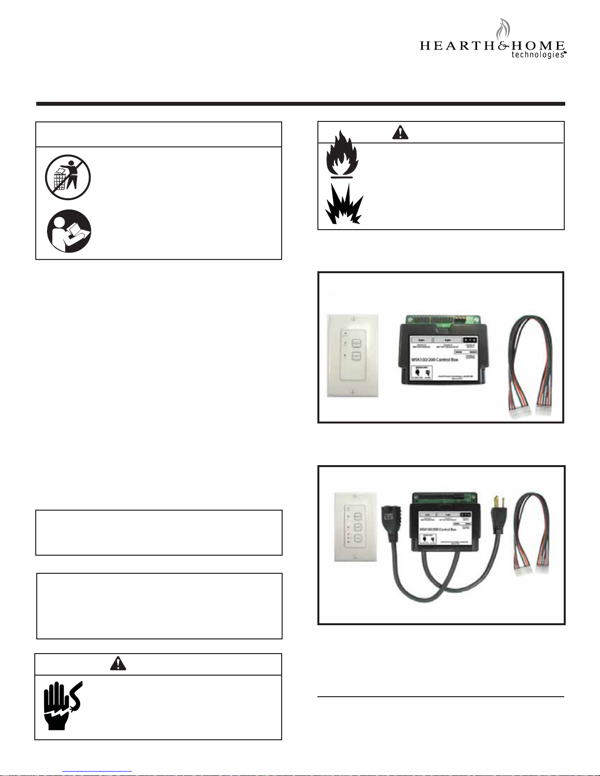
Figure 1. Items included in the WSK100 Wall Switch Kit
INTRODUCTION
The WSK100 and WSK200 wall switches are designed to
switchthefireplaceonoroff,andthepilotfunctionactivates
the pilot flame as well. These wall switches interface with
Intellifire™systems only.
INSTALLATION PRECAUTIONS
This wall switch is tested and safe when installed in
accordance with this installation manual. Do not install
any components that may be damaged. Do not modify,
disassemble,orsubstituteany of the components included
with this kit. Installation of this unit must be done by a
qualified service technician.
Placement of this wall switch may affect performance.An
assessmentofthespaceshouldbedonepriorto installation
for optimum performance. See Section 1.1 for location
recommendations.
NOTE:Theelectricaljunctionboxprovidedwiththe fireplace
must be wired with 110 VAC before installing this kit. See
owner’s manual for details.
WARNING
Shock Risk
WARNING
Inspect components for damage. Damaged
parts may impair safe operation.
• Do NOT install damaged components.
• Do NOT install incomplete components.
• Do NOT install substitute components.
Report damaged parts to dealer.
DO NOT DISCARD THIS MANUAL
CAUTION
•Importantinstallationand operation instruc-
tions included.
• Read, understand and follow these
instructions for safe installation and
operation.
• Leave this manual with party responsible
for use and operation.
Do NOT provide any power to this unit
until all wiring is complete.
•May destroy parts of this device and
render it unusable.
May lead to possible electrical shock.
•
NOTE: Allwiring should be done by a qualified electrician and
shall be in compliance with local codes and with the National
Electric Code ANSI/NFGA No. 70 - current (in the United
States),orwiththe current CSAC22.1 CANADIANELECTRIC
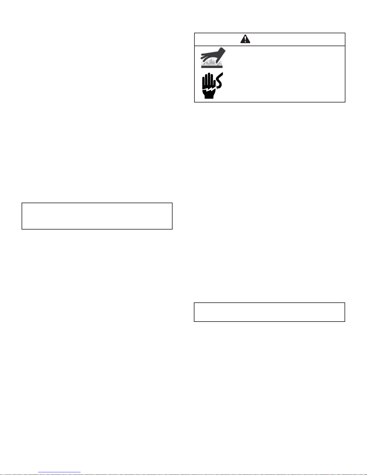
CODE (in Canada). Figure 2. Items included in the WSK200 and WSK210 Wall Switch
Kit. (Delay circuit not shown).
Wall Switch Control Box Wiring Harness
Wall Switch Control Box Wiring Harness
2
1.2 Wiring the wall switch
1.0 INSTALLATION INSTRUCTIONS
1.1 Determine Location
Determine the location for the wall switch. The selected
location should be in the same space as the gas fireplace.
Neverplacethisunit in a separate room.Thedistance from
the fireplace to the switch may be up to 50 ft.
The switch should be mounted into a UL-listed electrical
junction box. The junction box should be dedicated to this
wallswitch.Never install this wallswitch into a junctionbox
that is shared with other electrical service or devices. If
possible,install this unit onan interior wall ofthe residence
at a recommended height of 5 ft from the flooring.
Should the switch be installed on an exterior wall, be
certain wall insulation is kept intact and not damaged or
dislodged during the installation of the electrical junction
box. For exterior wall installations, it is recommended that
the junction box be sealed with caulking material. This will
minimize heat loss through this location.
1. Install the control wire from the fireplace to the switch
location.Usecautionnot to stress the wire around tight
or sharp corners. Do not run the control wire adjacent
to existing or future phone, data, cable, or electrical
lines. The wire should not come into contact with any
partofthe fireplace exterior withtheexceptionofwhere
it exits the outer wrap. Feed the wire to the electrical
junctionboxandthrough a provided or approved strain
relief.
2. Strip outer casing back about 1-1/2 inch. Use caution
to avoid stripping inner wires.
3. Strip the white or yellow, red and green wire casings
back about 3/8 inch.
4. Use a screw driver to connect the red wire to the “R”
terminal,white oryellowwiretothe “Y” terminal,andthe
green wire to the “G” terminal. Do not overtighten.
5. Use the screws provided to mount the switch to the
electrical junction box right side up.
6. Installprovided cover plate usingthescrews provided.
Do NOT use a substitute cover, even though it may
fit.
NOTE: Wiresupplied on theunit willbe red, whiteand green.
Wire purchased separately will be red, yellow and green.
1.3 Installing the Control Box
1.Placecontrol box into thebase pan area ofthe fireplace.
Place unit as close to the louvers or decorative front as
possible and to either the left or right side.
2. Connect the red, yellow or white and green wires to the
R, Y and G labeled terminals on the control box.
3. Unplug the 8-pin wiring connector from the ignition
module box and plug it into the 8-pin connector slot on
the WSK control box.
4. Using the supplied wiring harness, plug the 8-pin
connector into the ignition module and the 6-pin
connector into the WSK control box.
5. Unplugthe3 volt adapter fromthegreen IPI module and
plugit into thespade terminals of theblack WSK control
box.
WARNING
Burn Risk.
Shock Risk.
•Do not install the control box when fire-
place is hot.
Do not plug control box in until all con-
nections are complete.
•
NOTE: TheWSK200 and WSK210 havea built intimer
to turn the blower ON and OFF.
1.4 Installing the Blower (WSK200/210 Only)
1. See fireplace owner’s manual on fireplace for location
of the blower.
2. Plug the power cord from the blower into the receiver
box.
3. Disconnect and remove the temperature sensor switch
and speed control (rheostat) from the fireplace.
3
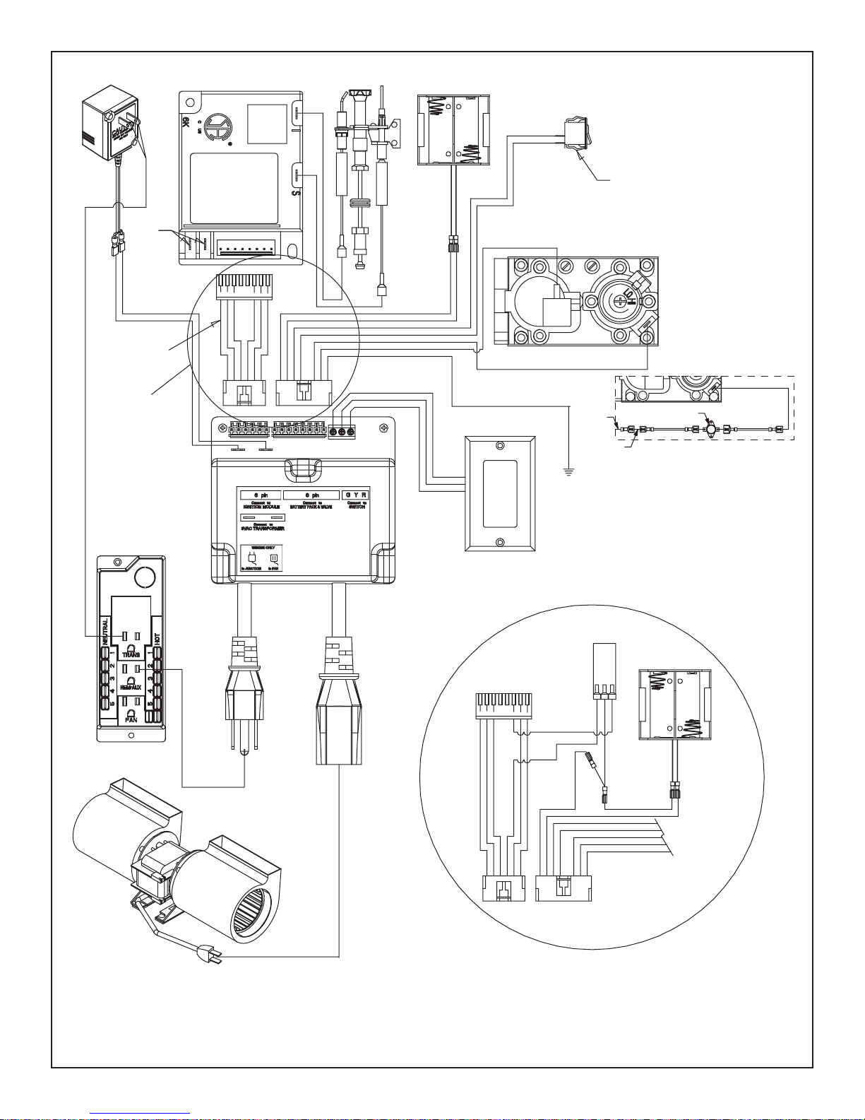
Figure 3. IPI wiring diagram with WSK100, WSK200 and WSK210 Wall Switch
WSK-100/200
CONTROL BOX
ORG
WHT
WSK210 DETAIL
DETAIL A - A
A - A FOR
SEE DETAIL
GRN
BLK
GRN
SWITCH
ON/OFF
ONLY
WSK210
CIRCUIT
DELAY
PACK
BATTERY
BLK
ORG
GRN
BRN
BRN
RED
BLK
RED
BRN
BLK
GRN
BLK
ORG
GROUND
J-BOX (110V)
ORG
GRN
BLK
ORG
GRN
BRN
BRN
RED
BLK
RED
YEL
GRN
PILOT
PACK
BATTERY
BRN
BRN
DEXEN IPI VALVE
WALL SWITCH
IPI MODULE
RED
BRN
BLK
GRN
BLK
ORG
NOT
USED
(7) 12" WIRES
BUNDLED
MINIMUM
NOT
USED
GRN BLK
BLK JUMPER
DETAIL B-B
FOR B-VENT
APPLIANCES
BLU
HIGH LIMIT SWITCH
BLK JUMPER

4
3.0 TROUBLESHOOTING
Condition (at time of power failure) Result
Wall switch is in ON mode with the main
flame on and has no battery backup or has
dead batteries.
The fireplace will shut down and the display lights in the wall switch will be off. When the
power is restored to the system, the display lights will remain unlit and the fireplace will
remain off.
Wall switch is in OFF mode with the main
flame OFF and has no battery backup or
has dead batteries.
The fireplace burner is not currently lit and will stay off. The display lights in the wall
switch will be off. When the power is restored to the system, the display lights will re-
main unlit and the fireplace will remain off.
Wall switch is in ON mode with the main
flame on and has battery backup. The fireplace will shut down and the display lights in the wall switch will be off. When
the power is restored to the system, the main burner flame and display lights will remain
off.
The wall switch is in OFF mode with the
main flame off and has battery backup. The fireplace will stay off and the display lights in the wall switch will be off. When the
power is restored to the system, the main burner flame and display lights will remain off.
Effects of Line Power Failure
The operating characteristics of your fireplace may vary during a power failure or power outage. The options listed below
will help determine the current state of your system.
2.0 OPERATION INSTRUCTIONS
NOTE: If the fireplace has an ON/OFF rocker switch
(located near the gas valve), the switch may either be
disconnected or turned to the OFF position. Rocker
switch is not required for operation of this control.
2.1 Wall switch button operation
On/Off Button
• Button Press: Turns fireplace ON
• Button Press: Turns fireplace OFF
During severe cold weather, homeowners may find that
activatingthepilotassistsinlightingthefireplace.Usethepilot
button to switch from “as-needed” pilot to “constant-on”.
Pilot Button
• Button Press: Turns Pilot to “Constant-on”
• Button Press: Turns Pilot to “As-needed”
Fan Speed Button (WSK200 Only)
• Button Press: Turns fan on high
• Button Press: Turns fan on medium
• Button Press: Turns fan on low
• Button Press: Turns fan on off
This manual suits for next models
2
Table of contents
Other Hearth and Home Technologies Switch manuals


