Hearth and Home Technologies WSK-MLT User manual

1
Copyright 2007
Hearth & Home Technologies Inc.
20802 Kensington Blvd., Lakeville, MN 55044
130-911G 12/07
WSK-MLT MULTIFUNCTION WALL SWITCH
- INSTALLATION AND OPERATING INSTRUCTIONS -
Figure 1.
Introduction
The WSK-MLT multifunctional wall switch is designed to
controlflameheight,blower speed,and auxiliaryfunctions
on your gas fireplace. For models equipped with the
Intellifiresystem (IPI), the cold climate function cancontrol
the pilot flame as well. The wall switch is equipped with
thermostat functions which can automatically control the
temperature in the room in which it is installed. The wall
switch interfaces with both intermittent and standing pilot
systems. An auxiliary function provides 110-120 VAC
sourcefor added featuresthe fireplace may haveinstalled.
Electrical ratings for the control box are 110 VAC, 60 Hz,
and is required for operation of this device.
Installation precautions
Thisremoteistestedandsafewheninstalledinaccordance
with this installation manual. It is your responsibility to
read all instructions before starting installation and to
follow these instructions carefully during installation. Do
not install any components that may be damaged. Do not
modify, disassemble,or substitute any of the components
included with this kit. Installation of this unit must be done
by a qualified service technician.
Placement of this wall switch may affect performance
or accuracy of the automatic (thermostat) control. An
assessmentofthespaceshouldbedonepriortoinstallation
for optimal performance. See the installation instructions
section I for recommendations.
1.0 Installation instructions
1.1 Determine location
Determine the location for the wall switch. The chosen
location should provide an accessible location in the
same space as the gas fireplace. Never place this unit in
aseparate room. The controlwire suppliedwith this switch
is 33 ft (10M) in length. The distance from the fireplace to
the switch may be lengthened provided that the wire used
neverexceeds50ft,andthatthedistancefromthefireplace
to the switch never exceeds 30 ft.
The switch should be mounted into a listed electrical junc-
tion box. The junction box should be dedicated to this wall
switch. Never install this wall switch into a junction box
that is shared with other electrical service or devices. If
possible,install this unit on aninterior wall of the residence
at a recommended height of 5 ft from the flooring. Should
the switch be installed on an exterior wall, be certain wall
insulationis kept intact and notdamaged ordislodged dur-
ing the installation of the electrical junction box.
For exterior wall installations, it is recommended that the
junction box be sealed with caulking material. This will
minimize heat loss through this location and improve the
accuracy of the automatic (thermostat) operation.
WARNING
Shock Hazard
Do not provide any power to this unit until all
wiringiscompleted.Failure todo somay destroy
parts of this device and render it unusable, and
may lead to possible electrical shock.
Fire Hazard
Modification of any parts or installation of
damaged components will void the warranty,
and you may possibly cause a fire hazard.
NOTE:The electricaljunctionbox providedwiththe fireplace
must be wired with 110 VAC before installing this kit. See
owners manual for details.
All wiring should be done by a qualified electrician and
shall be in compliance with local codes and with the
National Electric CodeANSI/NFGANo. 70- current (in the
United States), or with the current CSAC22.1 CANADIAN
ELECTRIC CODE (in Canada).
CONTROL
BOX
CONTROL
WIRE
WALL SWITCH
COVER
PLATE
FLAME
SOLENOID
2
WIRES WITH LABEL "FOR USE WITH WALL SWITCH
ONLY" (LOCATED UNDER FIREPLACE)
BROWN YELLOW
or
WHITE
BLACK
TOGETHER
CONNECTED
FACTORY
FAN THERMOSTAT
YELLOW
YELLOW
FLAME ON
3V DC
GREEN
RED
BROWN
BLACK
GROUND
BROWN
ADAPTER WIRES
BLACK
RED
RED
BLACK
FLAME HIGH/LOW
SOLENOID
FLAME
MODULE
IPI
ORANGE
G
W*
R
8
7
6
5
4
3
2
1
BATTERIES
ORANGE
CONNECTION
FAN
PLUG
AC BLACK
BLACK
G W* R
REAR VIEW
FRONT VIEW
CONNECTION
AUX
GREEN
PIGTAIL
GROUND
RED
RED
GREEN
ORANGE
VALVE
IPI
(MALE/FEMALE)
RED
RED
(FEMALE/MALE)
BLACK
RED
GROUND PIGTAIL
GREEN
BROWN
BROWN
USED
(LOCATED UNDER FIREPLACE)
WIRES WITH LABEL "FOR USE WITH
WALL SWITCH ONLY"
VALVE
FACTORY
CONNECTED
TOGETHER
PLUG
CONNECTION
AUX BLACK
CONNECTION
FAN
YELLOW
FAN THERMOSTAT
FLAME
AC
FLAME HIGH/LOW
SOLENOID
ORANGE
BLACK
ORANGE
RED
RED
RED
BLACK
YELLOW
FRONT VIEW
W
RED
NOT
BLACK G
REAR VIEW
R
R
W
YELLOW OR
WHITE RED
GREEN
G
USED
NOT
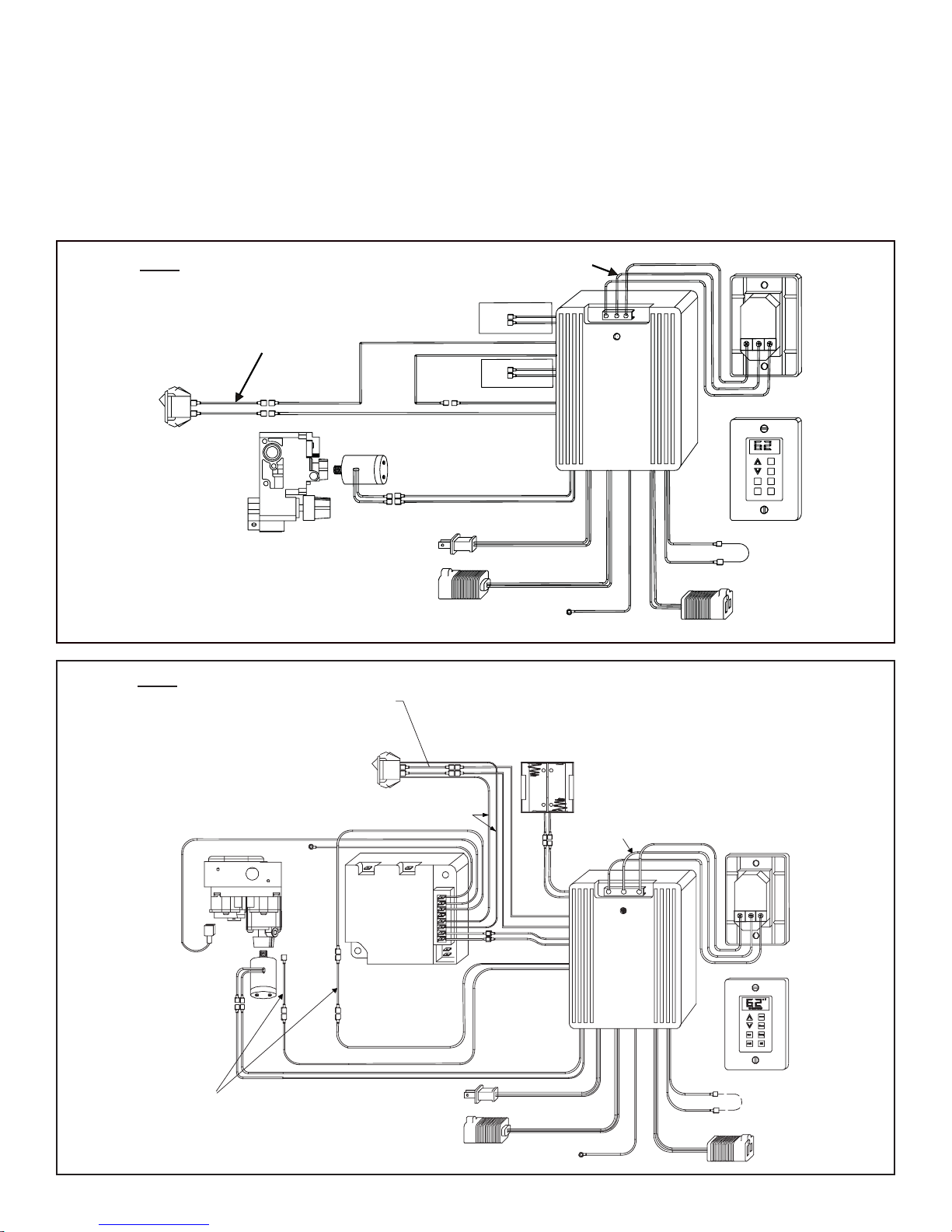
Figure 2. Standing Pilot Wiring Diagram
Figure 3. Intellifire (IPI) Wiring Diagram
to the electrical junction box and through a provided or
approved strain relief. Using a screw driver, connect the
red wire to the “R” terminal, the yellow or white wire to the
“W” or “Y” terminal, and the green wire to the “G” terminal.
Donot over-tighten. Using the screws provided, mountthe
switch to the electrical junction box right side up. Install
provided cover plate using the screws provided. Do not
usea substitutecover eventhough itmay fit.Theprovided
one is specifically designed for the automatic (thermostat)
function of the unit.
1.2 Wiring the wall switch
Oncea location ischosen and the electricalbox is installed
proceedasfollows.Installtheprovidedcontrolwirefromthe
fireplace to the switch location. (Control wire for Heatilator
products is supplied with the fireplace). Use caution not
to stress the wire around tight or sharp corners. Do not
run the control wire adjacent to existing or future phone,
data, cable, or electrical lines. The wire should not come
into contact with any part of the fireplace exterior with the
exception of where it exits the outer wrap. Feed the wire
For units WITH factory installed Rocker Switch
*May be labeled as “W” or “Y”.
*May be labeled as “W” or “Y”.
For units WITH factory installed Rocker Switch
*
*

3
1.3 Installing the control box
Figure 4. Standing Pilot Wiring Diagram
For units WITHOUT factory installed Rocker Switch
Standing Pilot Ignition:
Find these parts packed with WSK-MLT:
• Rocker switch
• Rocker switch bracket
• Strips of Velcro
• Black and white wire pigtails - (2)
• Female ends (only used on Standing Pilot
applications) - (2)
Cut male ends off black wires on each pigtail. Strip each
end of wire approximately 1/4 inch. Slide each stripped
wire into a female end and crimp. Slide rocker switch into
bracket until it snaps into place.Attach end of each pigtail
to each side of rocker switch. Find the top (brown) and
bottom (red) wires from the control box and attach to white
wiresfromrockerswitch.AttachoneblackwiretotheTH/TP
side of gas valve and the other to the TH side of the gas
valve.Attach the Velcro to the bottom of the rocker switch
bracket and mount in a convenient location next to gas
valve. (Refer to Figure 4).
For units WITHOUT factory installed rocker switch.
1. Placecontrolboxintothebasepan areaofthefireplace.
Place unit as close to the louvers or decorative front as
possible and to either the left or right side.
2. Connectthe red, yellowor white, and green wiresto the
appropriate labeled terminals on the control box.
For units WITH factory installed rocker switch.
3. Find the red and brown pigtail wire (labeled “ FOR USE
WITH REMOTE OR WALL SWITCH ONLY”) which are
attached to the fireplace ON/OFF rocker switch.
Standing Pilot Ignition: Connect these wires with the
red and brown wires extending from control box (Fig 2).
Intellifire (IPI): Connect these wires with the brown
wires extending from the control box (see Figure 3).
• Do NOT install the control box when fireplace is hot.
• Do NOT plug control box in until all connections are
complete.
* May be labeled as “W” or “Y”.
YELLOW
WHITE
BLACK
To
Thermopile
BLACK
BLACK
WHITE
WHITE
VALVE
FAN THERMOSTAT
YELLOW
YELLOW TOGETHER
CONNECTED
FACTORY
GREEN
RED
AC PLUG
BROWN
BROWN
G
W*
R
BLACK
RED
BLACK
RED
BLACK
BLACK
REAR VIEW
FRONT VIEW
CONNECTION
AUX
GREEN
GROUND PIGTAIL
RED
RED
FLAME HIGH/LOW
USED
NOT
G W* R
CONNECTION
FAN
ORANGE
ORANGE
SOLENOID
FLAME
USED
NOT
SWITCH AND WIRE
ASSEMBLY SUPPLIED
WITH WSK-MLT
CAUTION
4
Intellifire (IPI):
Find these parts packed with WSK-MLT:
• Rocker switch
• Rocker switch bracket
• Strips of Velcro
• Black and white wire pigtails - (2)
• Female ends (not used on IPI applications) - (2)
Slide rocker switch into bracket until it snaps into place.
Attachonepigtail to oneside of rockerswitch and the other
pigtail to the other side of the rocker switch. Find the two
brown wires from IPI module and attach them to the two
black wires from the rocker switch. Find the two brown
wires from the control box and attach them to the white
wires from the rocker switch. Attach the Velcro to rocker
switchbracket and place rocker switchnext to control box.
(Refer to Figure 5).
Proceed to Step 4.
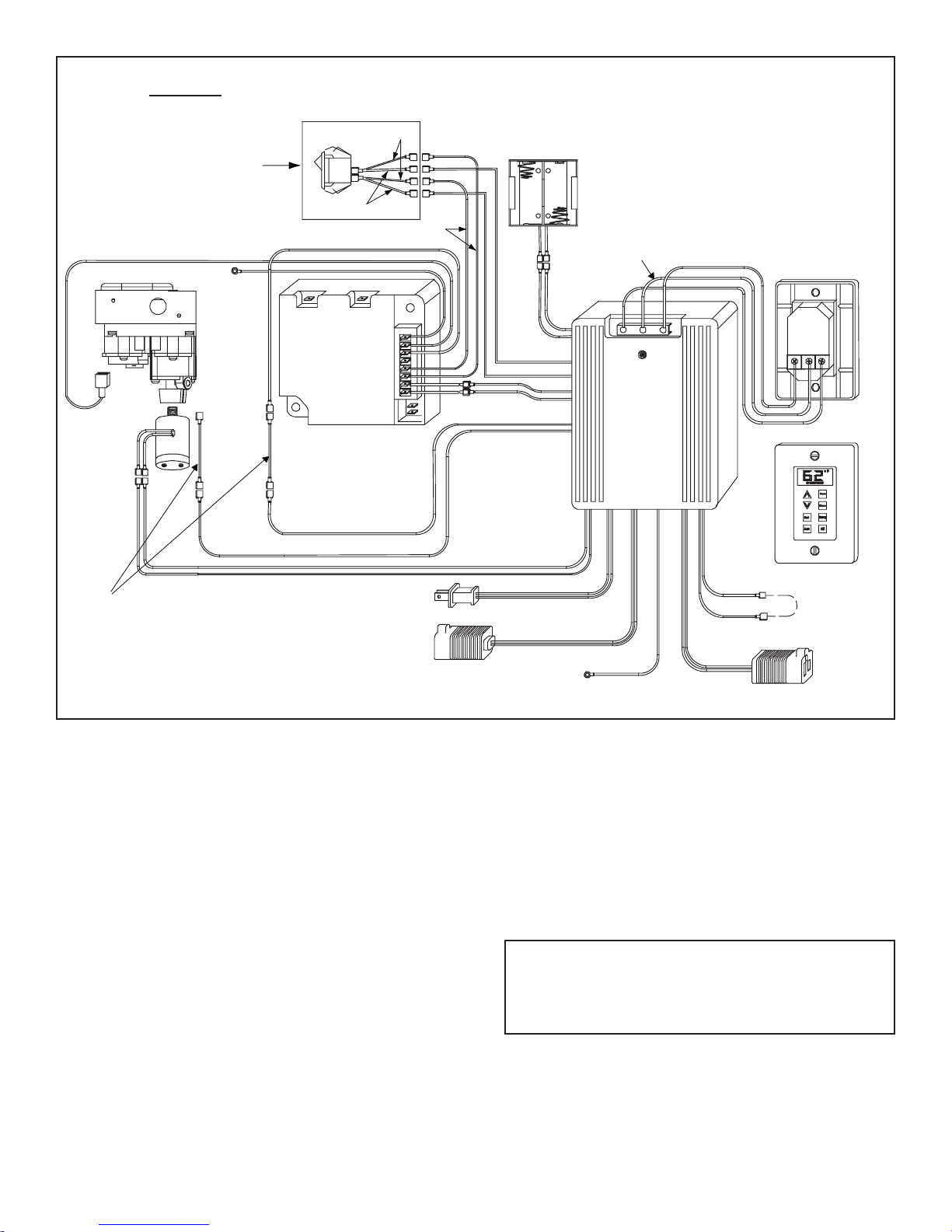
Figure 5. Intellifire (IPI) Wiring Diagram
For units WITHOUT factory installed Rocker Switch
* May be labeled as “W” or “Y”.
BROWN
WHITE
BLACK
YELLOW
or
WHITE
BLACK
TOGETHER
CONNECTED
FACTORY
FAN THERMOSTAT
YELLOW
YELLOW
FLAME ON
3V DC
GREEN
RED
BROWN
BLACK
GROUND
BROWN
ADAPTER WIRES
BLACK
RED
RED
BLACK
FLAME HIGH/LOW
SOLENOID
FLAME
MODULE
IPI
ORANGE
G
W*
R
8
7
6
5
4
3
2
1
BATTERIES
ORANGE
CONNECTION
FAN
PLUG
AC BLACK
BLACK
G W* R
REAR VIEW
FRONT VIEW
CONNECTION
AUX
GREEN
PIGTAIL
GROUND
RED
RED
GREEN
ORANGE
VALVE
IPI
(MALE/FEMALE)
RED
RED
(FEMALE/MALE)
BLACK
RED
SWITCH AND WIRE
ASSEMBLY
SUPPLIED
WITH WSK-MLT
Note: The fan rheostat has now been removed from the
circuit and is inoperable. Use the wall switch to change fan
speeds. The fan temperature sensor is still operable and
will turn the fan on and off when the fireplace heats up and
cools down.
5. Removethe screw and knobfrom the variableregulator
and discard.
6. Unscrew the nut from the regulator and discard.
7. Remove the bag containing a washer and blue and red
plungers from the side of the flame control solenoid.
8. Place washer on flame control solenoid (see Figure 6).
4. If equipped with a fan, plug the fan cord into the power
cord labeled “FAN”. Disconnect the two wires from the
fan thermostat switch on the fireplace. Disconnect the
two yellow wires from each other and connect them to
thefan thermostat switch. Use one of theexisting wires
on the thermostat to connect to the proper end on the
male terminated yellow wire.
5
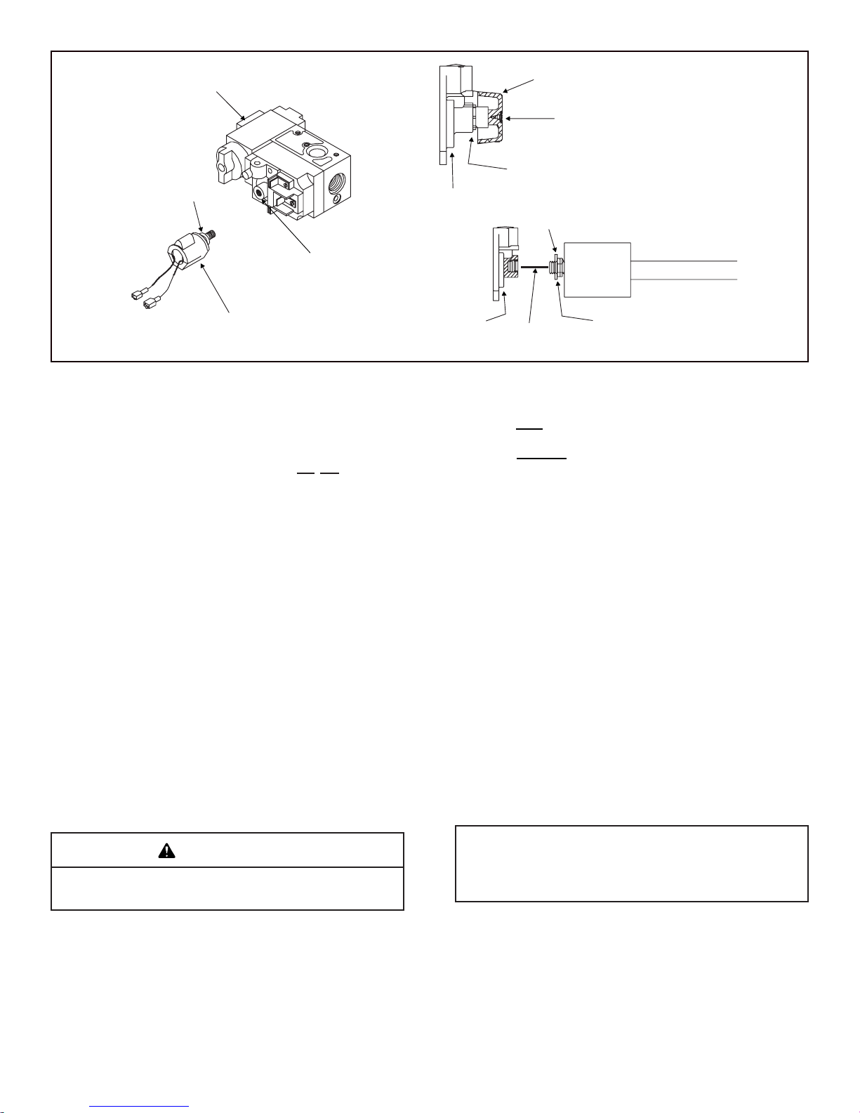
VARIABLE
REGULATOR
GAS CONTROL
VALVE
FLAME CONTROL
SOLENOID
KNOB
SCREW
NUT
VARIABLE REGULATOR
JAM NUT
VARIABLE
REGULATOR
SOLENOID
WASHER
WASHER
PLUNGER
Figure 6.
Intellifire (ipi) models only
For units with factory installed rocker switch see Fig. 3.
For units without factory installed rocker switch see
Fig. 5.
14. Disconnect main valve wire (green) from the front of
thevalve. Connectred control wire to red adapter wire
containing one large male end and one small female
end and connect to valve terminal (see Figure 3).
Connect the other red control wire to red adapter wire
containing one large female end and one small male
end and connect the green module wire (previously
disconnected from valve front).
15. Carefully unplug battery pack wires from IPI module.
Plug battery pack into red and black battery wires
(labeled “Battery”).
16. Plug red and black wires from control box (labeled
“3V DC”) to the red and black wires extending from IPI
module (labeled “3V DC”). Red connects to red, black
connects to black.
9. Insert the correct plunger (blue - natural gas, red - pro-
pane) into the flame control solenoid (see Figure 6).
10. Thread the flame control solenoid with correct plunger
into the thread hole in the variable regulator. Turn into
valve approximately two full turns. Do not tighten or
damage may occur.
11. Setthevalvemanifold pressure to thepropersetpoint.
The setpoint is adjusted by rotating the solenoid to
adjust its depth into the valve. Using a manometer
to monitor pressure, rotate the solenoid so that the
output is set to proper range.
12. Tighten the jam nut on the threaded shaft of the
solenoid against the valve regulator. Use an open-
ended ½” wrench to tighten the nut, while holding
the solenoid in the proper position. This step will en-
sure that the solenoid remains locked into the proper
position.
13. Connect orange wires from control box to the flame
control solenoid.
14. Ground the control box by attaching the green ground
wire (has round ring-terminal on end) to the fireplace
base pan or appropriate ground.
13. Connect auxiliary functions. This unit is equipped with
a 110 VAC supply cord (labeled “AUX”) for controlling
auxiliary functions such as an electric ember bed.
Lay the control box and wires flat on the base pan to avoid
potential overheating problems.
NOTE: Transformer supplied with the IPI system is NOT
used.Disconnectthe transformer fromtheelectricaljunction
box.Transformermay be removedfromthe fireplace, butwe
recommend leaving it connected to the IPI module.
CAUTION

6
2.2 Wall Switch Button Operation
(Refer to Figure 7)
Flame Button
• Button Press: Unit On / Flames High, Turns on auxiliary
power
• Button Press: Flames Low
• Button Press: Unit Off / Flames Off, Turns off auxiliary
power
Fan / Blower Button
• Button Press: Fan High (“3”)
• Button Press: Fan Medium (“2”)
• Button Press: Fan Low (“1”)
• Button Press: Fan Off
Temperature Button
• Button Press will toggle between Automatic and Manual
Operation
• PressandHoldthebuttonfor3secondstotogglebetween
Fahrenheit and Centigrade Temperature Display.
Automatic Operation: Controller will monitor temperature
and control unit according to the set point.
ManualOperation: Controller willnotautomatically change
settings.
SET
Set Temperature Button
• Button Press: Displays Set Point
• Use Up and Down Arrows to Adjust Set Point
• Press Set Button to Store New Set Point
Temperature Set Point can be adjusted between the ranges of:
45-900Fahrenheit or 7-320Centigrade
NOTE: The controller will turn off the fireplace at 20F over
set point and turn it back on at 20F below set point.
Up and Down Arrows
• Push to adjust set point temperature under automatic
control.
AUX
Auxiliary Button
• Button Press: Turns on auxiliary power
• Button Press: Turns off auxiliary power
Can be operated independently of all functions.
2.0 Operating Instructions
For units WITH factory installed rocker switch.
The ON/OFF rocker switch on the fireplace (located near
the gas valve) must be in the “OFF” position for use with
theWSK-MLTsystem.TheON/OFFrockerswitch will NOT
function with this device on Intellifire (IPI) models except
during a power outage.
For units WITHOUT factory installed rocker switch.
The ON/OFF rocker switch now installed on the fireplace
must be in the OFF position for use with the IPI or stand-
ing pilot system. The ON/OFF rocker switch will only be
used to control the fireplace in a no-power condition. For
standing pilot systems use the rocker switch to turn the
fireplace on and off. When power is restored switch the
rocker switch to OFF. For IPI system refer to “Operation
Under Battery Power” for instructions.
After all connections are made and the control box is
grounded, plug power cord into the fireplace junction box.
The wall switch will be functional at this time.
Figure 7.
<>
2.1 Setting Flame Height/manifold pressure
(To be done by a qualified service technician). Upon initial
power-up of this device, valve pressure must be set for
flame adjustment.
• Loosen output pressure tap on valve and connect with
pressure manometer.
• Press flame button once (Fig. 7); fireplace will light with
flames on high.
• Turn solenoid clockwise to increase pressure, counter-
clockwise to decrease pressure until manifold pressure
on high is 3.5” water column for natural gas (NG), 10.0”
water column for propane (LP).
• Oncepressureisachievedspinjam-nuton solenoid stem
tight against regulator face to prevent rotation. Do not
overtighten.
• Press flame button twice to turn fireplace off.
• Remove manometer tube and tighten or close pressure
tap. Use a soap solution to carefully check the pressure
tap for leaks.
NOTE: The temperature displayed by the wall switch may
take up to 30 minutes to stabilize on initial power-up.
NOTE: Check control box and assure switch is in the “OFF”
position. This switch is only used on Intellifire (IPI) control
systems under battery operation.
7
INTELLIFIRE (IPI) MODELS ONLY
Cold Climate Button
• Button Press: Turns on Climate Control
• Button Press: Turns off Climate Control
Thisallows the pilot flame to stay litwhen activated, a ben-
efit of this is reduced condensation on the glass at start-up
in colder climate conditions.
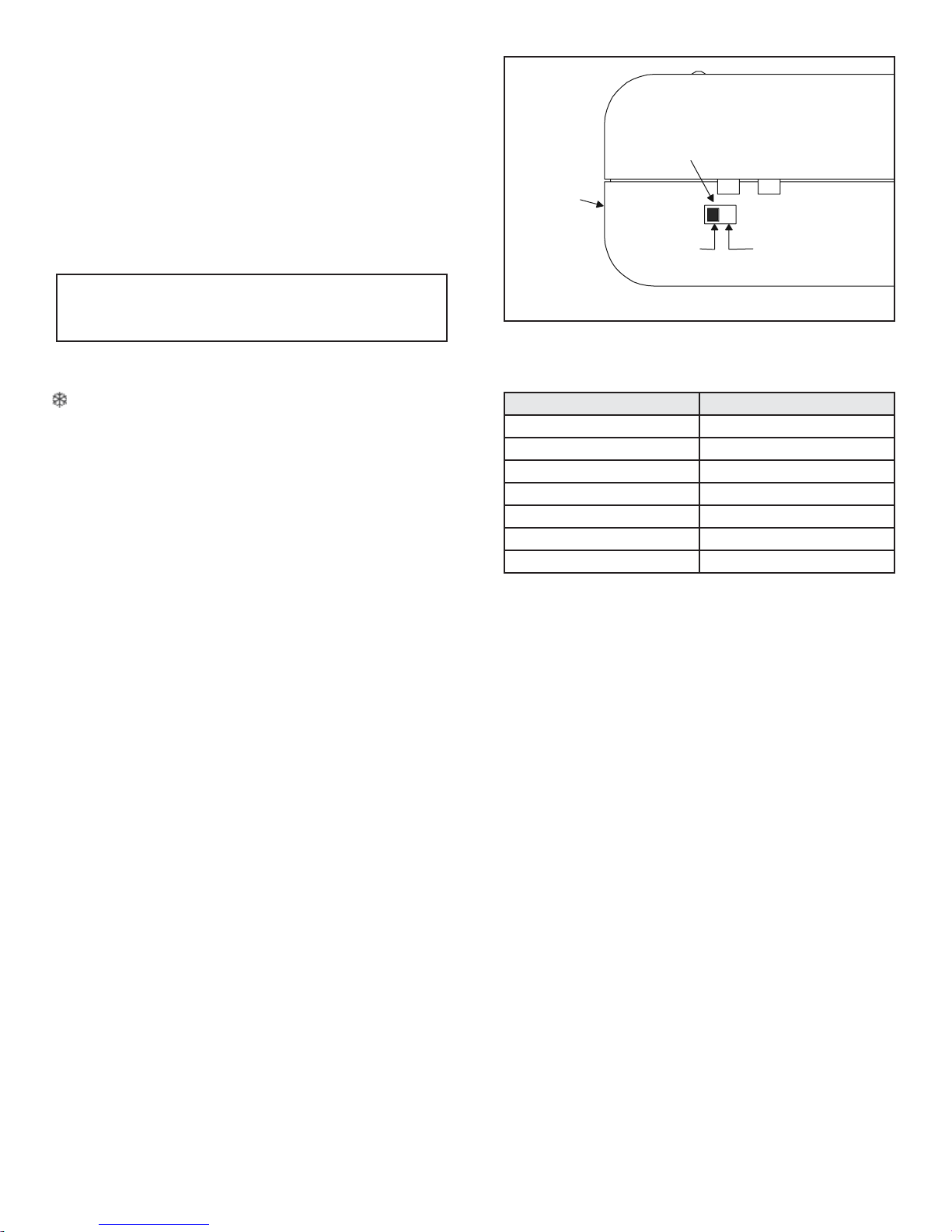
Operation Under Battery Power
Aswitch on the control box allows for battery power under
no-power conditions (see Figure 8). By controlling the
power supply with this switch, the batteries are supplying
power only when needed, thus extending battery life. The
switch also provides a convenient means for switching to
battery power should there be a loss of 110 VAC power to
the control box.
• In the event of a power failure, switch the battery
operation switch to the “Battery ON” position.
• The fireplace can now be turned on and off with the ON/
OFF rocker switch located near the gas valve.
• The wall switch functions will not operate under battery
power.
• Underbattery controlthe onlyavailable functionis flame
“On” and “Off” in the high position.
• To maximize battery life, and to restore full function
capability of the wall switch, flip switch to “OFF” position
after 120 VAC power is restored.
SERVICE PARTS LIST
Child Proof Mode
To Enter Child Proof Mode:
• Pressthe UpArrow Buttontwice and DownArrowButton
once. The unit will send out 3 beeps and an indicator in
the LCD panel will show that the child proof is on.
To Leave Child Proof Mode:
• Pressthe UpArrow Buttontwice and DownArrowButton
once. The unit will send out 3 beeps and the indicator in
the LCD panel that shows that the child proof is on will
disappear.
Figure 8
DESCRIPTION SERVICE PART NO.
SOLENOID HTI-17-006
WALL SWITCH/KEY PAD HTI-12-007
CONTROL WIRE HTII-23-007
COVER PLATE HTI-21-007
CONTROL BOX HTI-13-007
ACTUATOR PINS HTI-17-116
SWITCH KIT HTI-25-007
BATTERY
OPERATION
SWITCH
“BATTERY ON”
POSITION
POSITION
CONTROL
BOX
“OFF”
NOTE: When in Child Proof Mode, only the arrow buttons
will have functionality. Unit can enter Child Proof when the
fireplace is on or off.
Table of contents
Other Hearth and Home Technologies Switch manuals


