Heat Outdoors QHC18MR User manual
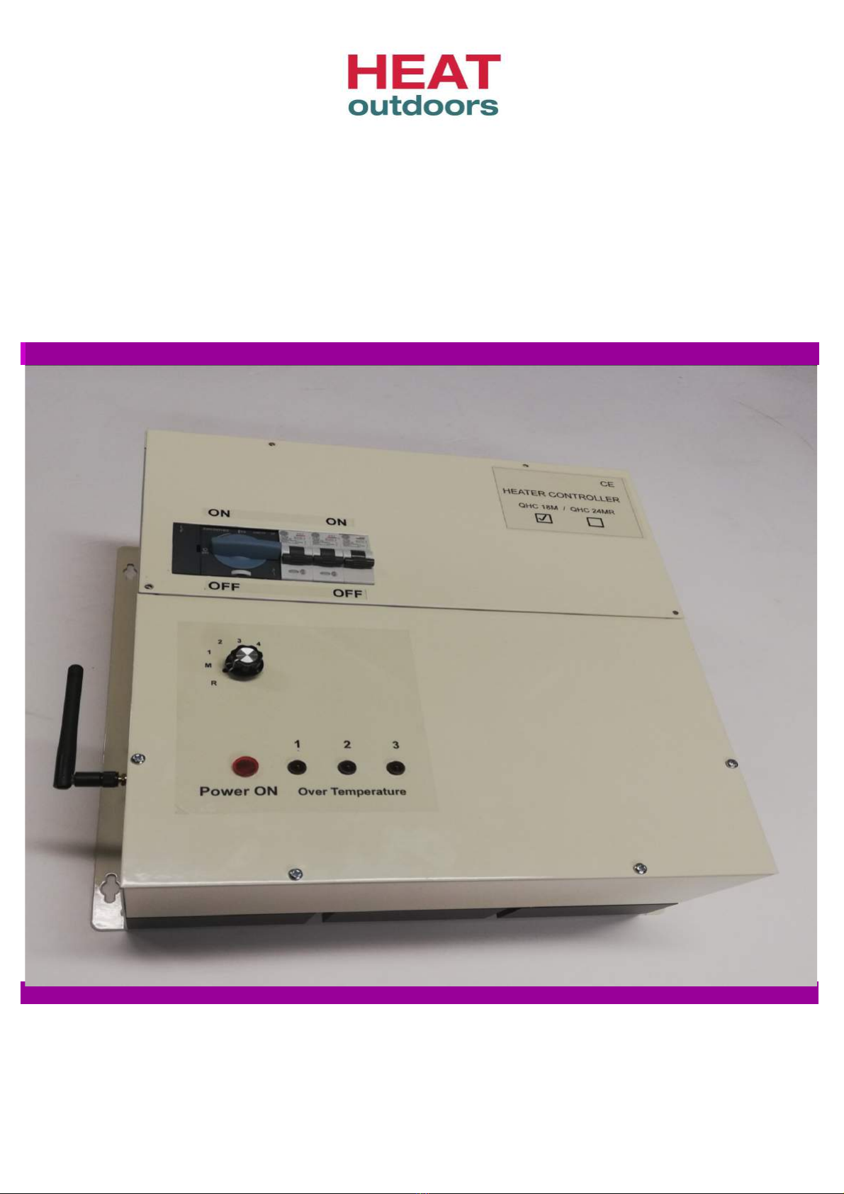
QHC18MR 18kW Heater Controller
3 channel (Receiver)
Remote & Manual Operation
Quick Start Gui e & Instructions
Three phase 415v / Three Zone / Remote & Manual / Soft start
Quick Start for QHC18MR
18kW Heater Controller with Soft start
Remote & Manual Operation.
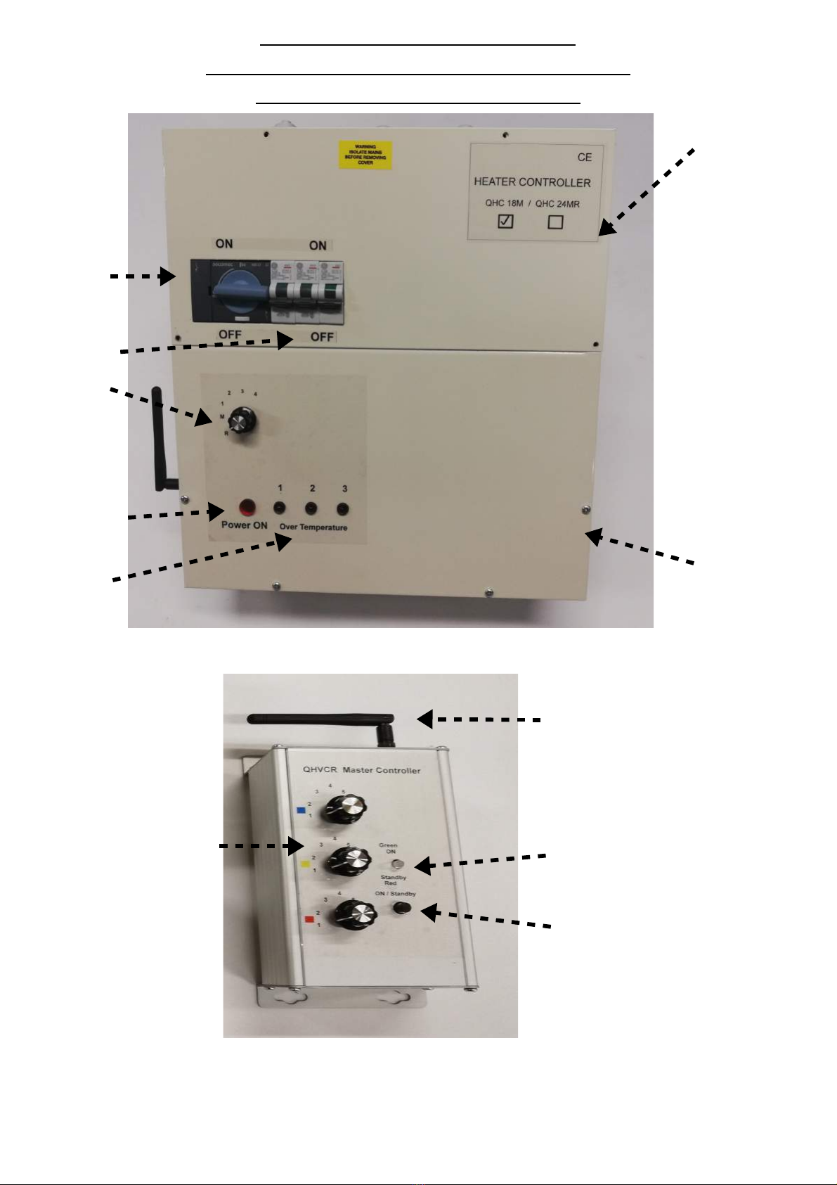
Service hatch
Isolation
switch 32A
O/P MCBs
32A Type C
Power
control ial
5 settings
Manual &
Remote
Power ON
in icator
Over Temp
in icators Front panel
Fig 1
QHVCR remote Master Controller
Antenna
Power
Power control ials
Blue, Re & Yellow Device ON / Stan by In icator
ON / Stan by Switch
Fig 2
Page 1
Quick Start for QHC18MR
See fig's 1,5 & 6
1) Start by removing the servi e hat h. Remove the 4 fixing s rews, 2 at the top and 2 in the orners. There is a
Din Rail revealed on e the servi e hat h has been removed.
2) Use the able grommets to bring the ables into and out of the ontroller base .
3) Conne t the Mains IN as follows, Neutral blue wire to terminal #1 – Neutral IN, Live Brown wire to
terminal #2 – L1 IN, Live Black wire to terminal #3 – L2 IN, Live Grey wire to terminal #4 – L3 IN
see fig 5.
4) There are two methods on how to onne t the Infrared Heaters to the ontroller.
a) Conne t the heater or heaters Live to O/P1 terminal #5 switche L1, the O/P has a maximum load apa ity
of 6kW or 32amps. O/P1 an also be referred to as Zone 1. Conne t the heater Neutrals to Neutral Out
terminals #8 – 13. The heater Earth is onne ted to the Earth terminal #14. The remaining heaters should be
distributed a ross the remaining two outputs O/P2 & O/P3.
Please ensure that the load is balan ed a ross the output terminals #5 – 7.
Do not excee the maximum loa capacity per output.
b) Conne t to an external distribution box. Conne t O/P1 to terminals marked 1, O/P2 to terminals marked 2
and O/P3 to terminals marked 3. Conne t the Neutral OUT to the blue terminals marked N. Conne t the Earth
to the green/yellow Earth terminals. Then onne t the heaters to the other side of the terminals to the
appropriate onne tions. Live onne tions to terminals 1,2&3. Neutral onne tions to blue terminals N and
Earth onne tions to the Earth terminals. See fig 6.
5) When all onne tions are omplete and onne ted orre tly, he k on e again that the wiring is orre t as per
3) & 4). Then repla e the servi e hat h over and tighten the fixing s rews.
6) Turn ON or re onne t the Main Power to the ontroller. The red neon lamp on the front panel will illuminate
to indi ate that the unit is LIVE.
7) There are auxiliary devi es su h as mains operated PIR motion dete tors & timer (lag) swit hes. These an be
onne ted to terminals #15 – 17. External push button swit hes whi h are voltage lean or free an be
onne ted to terminals #18 – 20. Go to pages 7,8 & 9 and see fig's 9 to 12.
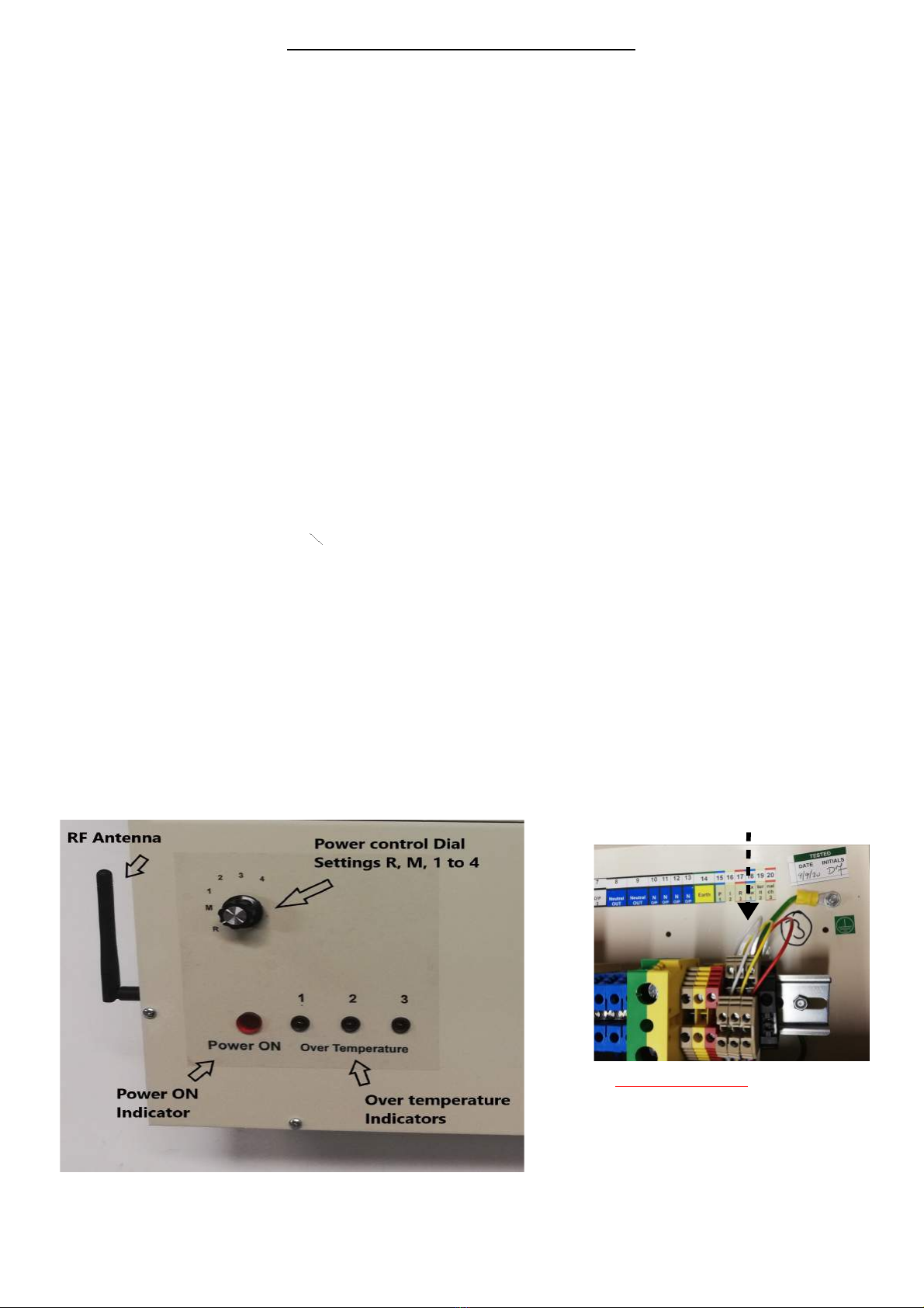
8) Remote operation ensure the Power ontrol dial is in position R. Follow the instru tions in page 3 for
QHVCR remote Master Controller .
9) Manual operation move the position of the dial through positions M, 1, 2, 3 & 4.
M = 0%, 1 = 33%, 2 = 50%, 3 = 66%, 4 = 100% see fig 3.
Remove wire links white, yellow & red.
Fig 4
IMPORTANT
If wire links or external push button
switches are not fitte the unit will not
operate when S2 is in the ON position.
See fig 4 &
Fig 3
Page 2
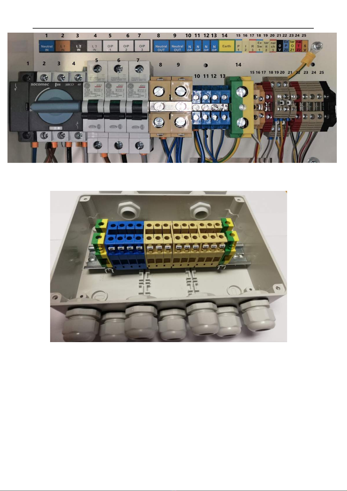
QHC18MR 18kW Heater Controller Din Rail & Connections
Fig 5
Distribution Box P/No. QHDB18 or QHDB24
Fig 6
Terminals 1 – O/P1, Terminals 2 – O/P2, Terminals 3 – O/P3
Blue terminals N – N out, Green/Yellow terminals – Earth
This item is sol separately
Important ! Only a qualifie electrician shoul install this evice.
Page 3

Controller Setup Manual Operation S1 & S2
To access S2, remove both the service hatch & front panel.
S2 is found on the printed ir uit boards QHPCB-A. There is a set on ea h board. See fig. 8
PIR & External Swit hes OFF - S2 Slide swit h is set in the Off position (sele t 2), fa tory set.
Set up for use with PIR's & External Swit hes – S2 Slide swit h must be set in the ON position (sele t 1)
See fig. 8
S1 – Manual & Remote is ontrolled using the power ontrol dial on the front panel. See fig. 1
This is set by turning the Power ontrol dial to R (remote) or M (manual) ontrol. There is a harness from the
Power ontrol printed ir uit board on the front panel down to S1 Remote ontrol ON/OFF header of ea h
QHPCB-A board on the ontroller base. See fig 16 page 10.
Fig 8
Fig 7
LED's D5,6 & 7 on the PCB
These are bi- olour LEDs and indi ate the status of the ele troni board.
LED D7 marked STAT, will flash GREEN to indi ate the board is running and the phase is dete ted.
If the D7 LED was RED this indi ates that the phase has not been dete ted and the board will not run.
LED's D5 (+5V) & D6 (+12V) are GREEN to indi ate that the on board power supply +5v & +12v are
both present and running. See fig. 7
Page 4

QHVCR remote Master Controller (Transmitter)
Fig 9
Supplied separately
1) There are three ontrol dials Blue, Yellow & Re one for ea h zone. The QHCxxMR units are preset
to operate in one of these zones. The QHCxxMR unit on e preset will only operate in that designated
zone. The fa tory setting is 1, this will be the Blue ontrol dial.
2) Turn ON the QHVCR unit by pressing the ON/Standby button on the front panel. The Led indi ator
will flash orange – green – orange – green and remain Green to indi ate that the unit is ready see fig 2.
3) The QHCxxMR unit is preset as a Blue zone (1). Turn the Blue ontrol dial to position 2. The heaters
onne ted to the QHCxxMR units will ome ON at the minimum setting 33%. Continue to turn the Blue
ontrol dial through position 3 to 5 until you rea h the desired setting. Settings are 1 = 0%, 2 = 33%, 3 =
50%, 4 = 66% & 5 = 100%.
4) QHCxxMR units whi h are preset to Yellow & Red zones are ontrolled by the Yellow & Red ontrol
dials respe tively and will operate as above see fig 9.
5) The QHVCR unit is powered by 3 x AAA battery's. The unit will automati ally go into standby mode
if the unit is ina tive for more than 30 se onds. When the unit goes into standby mode all the QHCxxMR
units will remain un hanged at the settings they were set at. Therefore the heaters will remain ON.
6) To hange a setting just press the ON/Standby button and pro eed as des ribed in 2) & 3).
However, while the QHVCR unit is ON, you an turn OFF all the heaters by pressing the ON/Standby
button. This is indi ated by the Led indi ator flashing Red.
7) The previous settings will be remembered and will be restored when you press the ON/Stand by button
again.
Please note: The QHVCR remote Master Controller an ontrol any number of
QHCxxMR ontrollers as long as they are within range, up to 100 meters *
(see spe ifi ation sheet for the QHVCR unit).
The QHVCR should be wall mounted.
* Longer antenna are available to extend the range up to 200 meters.
Page 5

Pairing (Programming) Devices
QHVCR & QHCxxMR
Fig 10
Pairing (programming) evices QHVCR (transmitter) an QHC18MR (receivers).
1) The Left Hand Side rotary swit hes (TEN) on both boards must be set the same.
The LHS swit h (TEN) is used to set the RF frequen y the setting must mat h on both
boards. There are 10 possible frequen ies that an be sele ted 0-9. If the settings on the LHS
swit h (TEN) do not mat h the devi es will fail to operate.
Designating the transmitter and re eiver. Both the left rotary swit hes are set at 0,
this ensures that the transmitter marked 0 will ommuni ate with the re eiver marked 0.
Setting the left rotary swit h to 1, so the transmitter marked 1 will ommuni ate with a
re eiver also marked 1.
If the transmitter and re eiver are not paired orre tly they will not ommuni ate and
therefore will not operate; transmitter marked 0 will not communicate with a
re eiver marked 1.
Remember a transmitter an be set at any number between 0-9 & the re eiver must be
mat hed orre tly.
2) The Right Hand Side rotary swit hes (UNIT) are for setting the devise to operate in a set
zone. There are 3 possible zones that the ontroller an be set to. The RHS swit h (UNIT)
should be set to 1,2 or 3.
Blue Zone 1 operation set RHS swit h (UNIT) to 1
Yellow Zone 2 operation set RHS swit h (UNIT) to 2
Re Zone 3 operation set RHS swit h (UNIT) to 3
See fig 10.
Note : QHCxxMR = QHC03MR, QHC06MR or QHC18MR
Page 6
PIR Motion Detectors Connection & Operation
PIR motion dete tors are passive infrared sensors, an ele troni devi e whi h is triggered by infrared light
from the movement of obje ts in its field of view.
We re ommend the QHPIR is used with our QHC ontrollers.
When using a PIR – S2 slide swit h must be in the ON position (sele t 1). See fig 8 page 4.
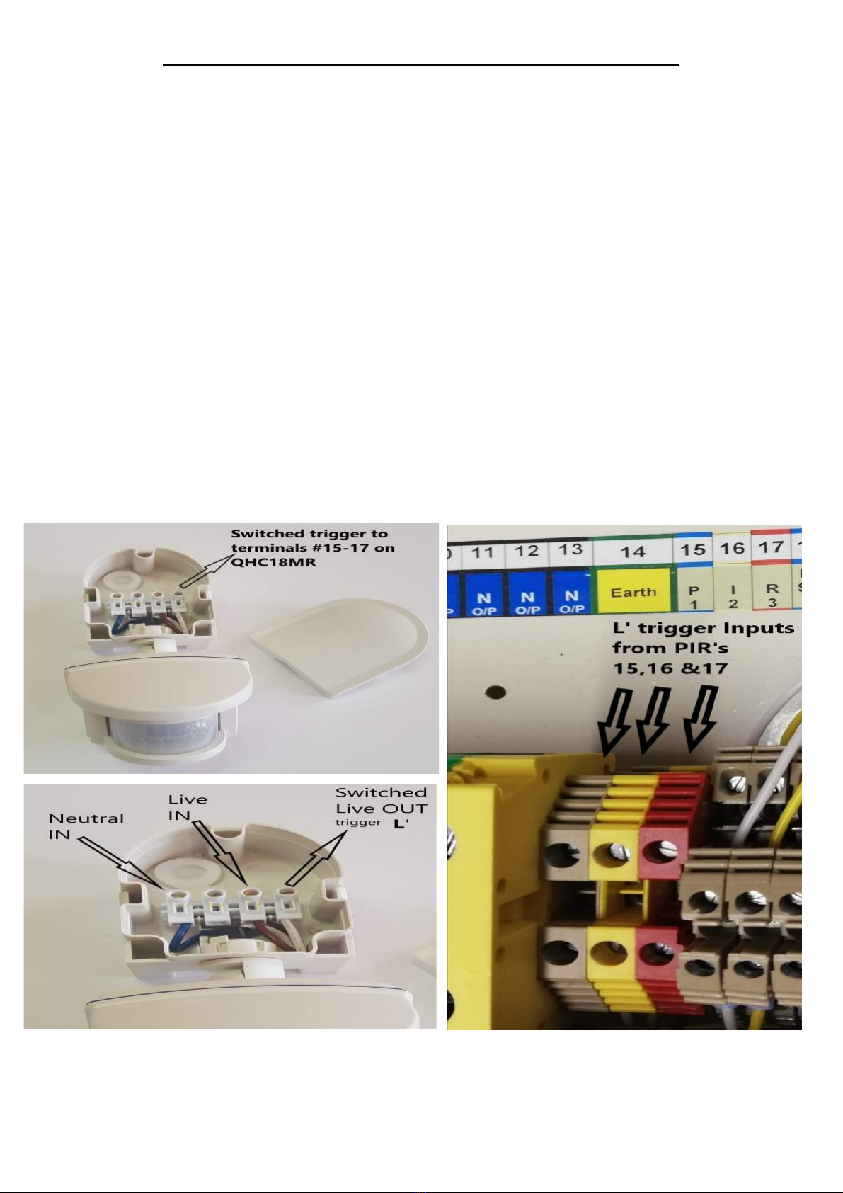
Remember there are 3 zones, Blue Yellow & Red. Conne t the Swit hed Live Out trigger L' to the PIR
input terminal #15, 16 or 17 for separate ontrol of ea h zone. Only 1 PIR per zone an be onne ted.
Blue zone = #15, Yellow zone = #16 & Re zone = #17. See fig's 6, 7 & 8.
For single PIR operation, a jumper link an be fitted onne ting the 3 inputs (terminals 15,16 & 17)
together. In this onfiguration 1 PIR will turn ON all 3 zones together.
The PIR when triggered, will also trigger the ontroller and turn on the appropriate zone. The ON time
will depend on the time set on the PIR. This is found on the underside of the PIR housing.
Note: PIR ON time is adjustable from 5 se onds to 15 minutes.
Note: a PIR should not be lo ated dire tly in front of an Infrared heater. The infrared light emitted from
the heater will keep the PIR permanently triggered and the motion dete tor will fail.
Please follow the instru tions provided with the PIR for installation and onne tion.
Fig 11 Fig 12
Page 7

External Switch Connection & Operation
Push On/Push Off & Timer (10 minute) function
External swit hes an be onne ted to the ontroller via terminals #18,19 & 20 a+b. This parti ular
terminal is a Double de k terminal. The swit h must be a normally open onta t swit h (NO) and
onta ts must be voltage free.
When using External Swit hes – S2 slide swit h must be in the ON position (sele t 1 ). See fig 8 page 4.
Remember there are 3 zones, Blue Yellow & Red. Conne t the swit h onta ts a ross the input
terminals #18,19 or 20 a+b for separate ontrol of ea h zone. See fig 13.
Only 1 external swit h an be onne ted per zone.
For single external switch operation, a link bar with mount s rews an be fitted onne ting the 3 input
(terminals #18,19 & 20) together. In this onfiguration 1 External Swit h will turn ON all 3 zones
together. See fig 14 & 15.
When the external swit h onta ts are losed this will trigger the ontroller and turn ON the appropriate
zone. The external swit h ontrols the Push ON/Push OFF or Timer fun tion for ea h zone.
The Push ON/Push OFF or Timer fun tions are pre-programed and must be spe ified prior to manufa ture.
Fig 13 Fig 14
External Swit h Input terminals 18,19 & 20 a+b Link bar fitted a ross the 3 inputs 18,19 & 20
Also shown above with test push swit h
Using a PIR or an External swit h to ontrol several ontrollers at on e is possible. If all the outputs are
required to operate as one output. Use the jumper link in the ase of the PIR and the link bar for the External
swit h. PIR example, onne t a jumper link a ross terminals #15,16 & 17. This turns the 3 inputs into 1 input.
So, one PIR L' trigger input will now ontrol all 3 outputs. If the same terminals #15,16 & 17 on several
other ontrollers are also onne ted in the same way using a jumper link. Then run a able one wire between
ea h ontroller onne ting ea h set of terminals #15,16 & 17 together. This setup will now allow several
ontrollers to be ontrolled by one PIR motion dete tor.
Note: Important this L' trigger is a live connection an the appropriate wire must be use .
External swit h example, this time use the Link bar to onne t a ross terminals #18a,19a & 20a. This
onne tion is voltage free so standard signal wire an be used. Conne ting the set of terminals on ea h
ontroller together allows for one External swit h to again ontrol several ontrollers at on e.
Page 8

Jumper Link (PIR) & Link Bar (External switch)
Jumper Link and Link Bar & Mnt s rews ID onns Red & Yellow with Jumper & Link Bar
Jumper Link fitted to inputs #15-17 (PIR) & Link Bar fitted to inputs #18-20 (External swit h)
Fig 15
Conne ting the Jumper Link to inputs terminals #15-17 allows for one PIR to ontrol the unit.
Conne ting the Link Bar to inputs terminals #18-20 allows for one external swit h to ontrol the unit.
Over Temperature Protection
There are 3 temperature sensors and 3 LED indi ators one for ea h zone. The LED indi ators are lo ated
on the front panel marked 1,2 & 3.When an over temperature situation is dete ted one of these will flash
to indi ate whi h zone has over heated. The ontroller will automati ally redu e the power to the
affe ted zone to 50%. (Note this is provided the initial setting is already greater than 50%).
With the power redu ed the temperature should return to normal working temperature.
If however after 30 minutes this does not happen and the over temperature indi ator is still flashing. The
ontroller will automati ally shut down (turn OFF) the affe ted zone, allow the zone to ool down for
another 30 minutes. The remaining unaffe ted zones will ontinue to work normally. Reset the unit by
swit hing OFF and then ba k ON using the mains isolation for the ontroller to re over.
If the over temperature ondition persists you are advised to turn off the zone using the appropriate MCB
on the front panel and all a qualified ele tri ian to address the problem.
Page 9
Fitting ID Connectors Re & Yellow
Fig 16
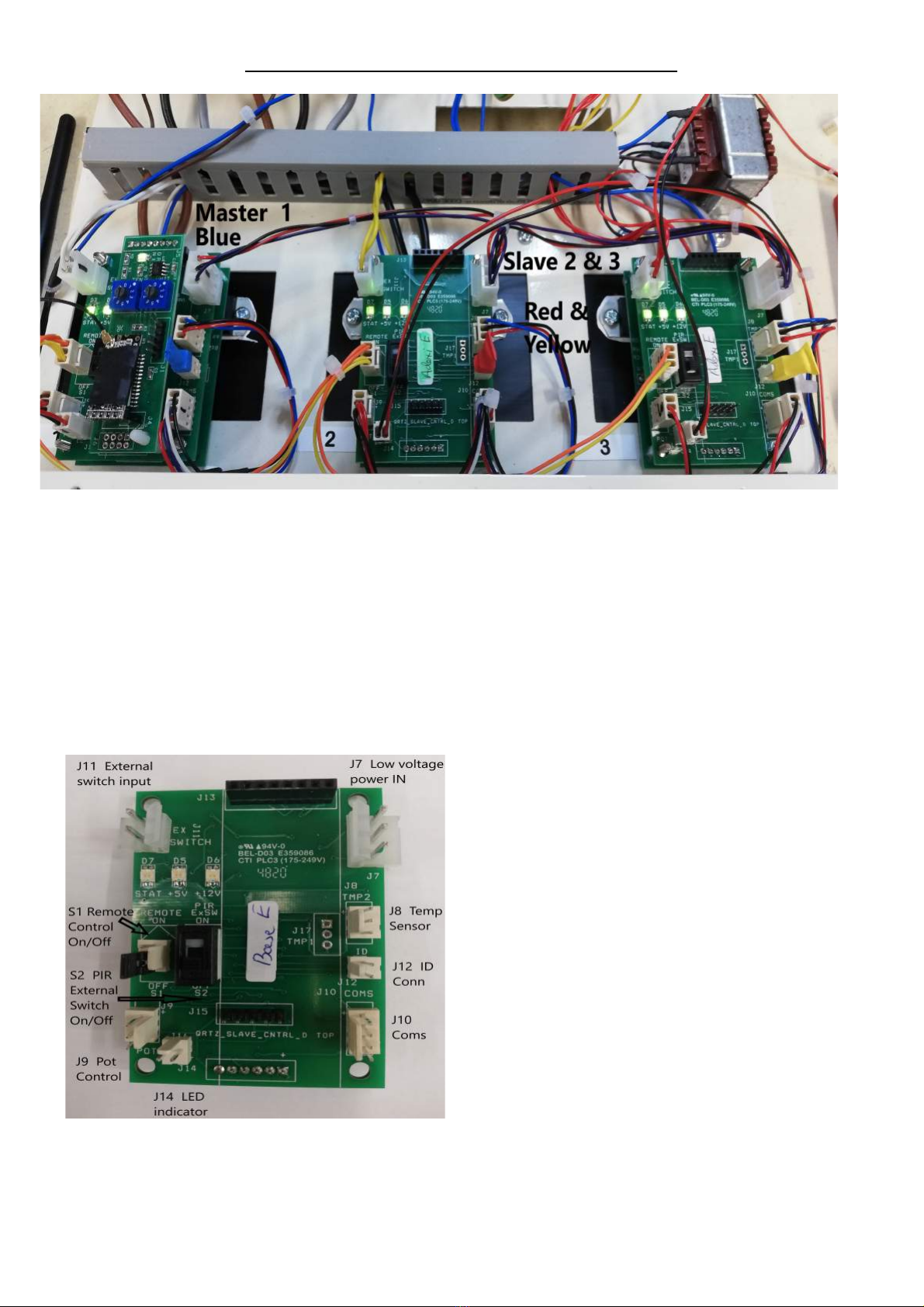
Master 1 printed ir uit board (PCB)is lo ated in position 1, phase L1. This is the main board that
ontrols the entire QHC18MR ontroller. The Slave 2 & 3 p b's are lo ated in positions 2 & 3, phases L2
& L3.
The Master 1 p b is fitted with the re eiver p b & antenna for ommuni ations with the QHVCR
transmitter, also fitted is the blue ID onne tor onne tor header J12 ID Conn, see fig 17. This blue ID
onne tor is very important, if this is not fitted the unit will not operate in remote mode. It is also important
that the ommuni ations harness between all three p b's is also fitted. This is essential for the Master to
ommuni ate with the two Slave p b's, the harness is onne ted to J10 Coms, see fig 17.
Normal default onfiguration leaving the fa tory is the
blue master ID onne tor is fitted to the Master 1 p b.
In this onfiguration all three outputs will behave as one.
To pair the ontroller & set the Zone with the QHVCR see
fig 10 page 6 and follow steps 1) & 2).
If however you want to set the 3 outputs as 3 separate
zones in the one ontroller as above in fig 15.
You must set the Right hand rotary swit h (Units) to
position 0 and then fit the Red & Yellow ID onne tors
to J12 on ea h p b's 2 & 3 see fig 16.
Using the QHVCR transmitter you now ontrol ea h
output separately.
These Red & Yellow ID onne ting are supplied as extras.
Fig 17
Page 10

CE RoHS Technical Data
Supply voltage : Three Phase 415V AC 50/60 Hz All O/P's with Soft start
Max. Loa capacity: 18 kilo Watts * (Loa must be balance across all 3 outputs max 6Kw each)
Over Temperature Protection: On each O/P - Le in icators 1,2 & 3
Mains I/P : Neutral (Blue) terminal #1
Live 1 (Brown) terminal #2
Live 2 (Black) terminal #3
Live 3 (Grey) terminal #4
Mains O/P : Switche Live 1 (Brown) terminal #5
Soft start Switche Live 2 (Black) terminal #6
Switche Live 3 (Grey) terminal #7
Neutral return out (Blue) terminal #8-13
Earth out (Green/Yellow) terminal #14
PIR I/P : Live trigger input Zone 1 terminal #15
Auxiliary Live trigger input Zone 2 terminal #16
Device Live trigger input Zone 3 terminal #17
Ext. Sw. I/P : Ext. SW1 Zone 1 terminal #18 a+b
Auxiliary Ext. SW2 Zone 2 terminal #19 a+b
Device Ext. SW3 Zone 3 terminal #20 a+b
QHVC-S I/P : 0V terminal #21
Auxiliary Zone 1 terminal #22
Device Zone 2 terminal #23
Optional Zone 3 terminal #24
5V terminal #25
IP Rating: IP53
Dimensions : 350mm x 330mm x 150mm Note : Terminal connections are the same
Weights : QHC18MR – 10 Kg for both the QHC18M
& QHC18MR controllers.
Unit 9 Stort Valley Industrial Estate, Bishop's Stortford, Hertfordshire, CM23 2TU, UK
Website: www.heat-outdoors.co.uk
Tel. 01279 466 500 Email: [email protected]
Other manuals for QHC18MR
1
Table of contents
Other Heat Outdoors Controllers manuals


Popular Controllers manuals by other brands


Speck pumps
Speck pumps Badu Eco Touch II Installation, operating and service manual

Jesco
Jesco C 2213 Operation & maintenance instructions

BMR
BMR HJ103RX User and service manual

Omron
Omron E5GC user manual

Faro Barcelona
Faro Barcelona 33974 installation guide

Lutron Electronics
Lutron Electronics Grafik Eye GRX-TVI Installation and operating instructions