Heat Outdoors QHC18MR User manual

QHC06MR 6kW Heater Controller
(Receiver)
Single Phase 240v / Single Channel / Sort Start
Remote peration

Quick Start for QHC06MR 6kW Heater Controller (receiver)
1) Remember isolate the Mains before removing the cover. Remove the cover by removing the 4
screws. There is a terminal strip connector for connecting the Mains IN and Mains O T.
2) se the three cable glands to bring the Mains cables into and out of the controller base .
3) Connect Mains IN - Live brown (2), Neutral blue (3) and Earth green/yellow (4) wires to
terminals marked Live IN (2), N IN (3) and Earth IN (4).
4) Connect the Infrared Heater - the brown Live wire to Load Out (7), the blue Neutral wire to N
Out (6) and the green/yellow Earth wire to Earth Out (5).
5) The trigger from a motion detector (PIR) QHPIR is connected to terminal PIR Input (1).
6) When all connections are complete and connected correctly, check once again that the wiring is
correct as per 3) & 4). Then replace the cover and tighten the fixing screws.
7) Turn ON or reconnect the Main Power to the controller. The red neon lamp on the LHS will
illuminate to indicate that the unit is LIVE.
The controller is now ready to be controlled by the wireless remote unit QHVCR. See
instructions for QHVCR operation, page 2 follow steps 8) to 14).
Important only a qualified electrician can install this device.
Remember to fit Type C MCB circuit breakers & a fused spur for each heater.
Page 1
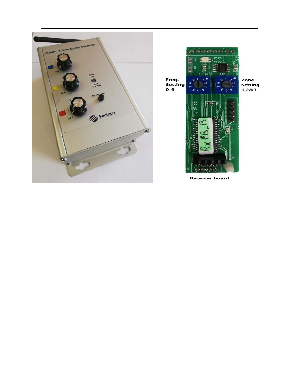
QHVCR 3 Zone Remote Master Controller (transmitter)
8) There are three control dials Blue, Yellow & Red one for each zone. The QHC06MR units
are preset to operate in one of these zones. The QHC06MR unit once preset will only
operate in that designated zone. The factory setting is 1, this will be the Blue control dial.
9) Turn ON the QHVCR unit by pressing the ON/Standby button on the front panel. The Led
indicator will flash orange – green – orange – green and remain Green to indicate that the
unit is ready.
10) The QHC06MR unit is preset as a Blue zone (1). Turn the Blue control dial to position 1.
The heaters connected to the QHC06MR units will come ON at the minimum setting 33%.
Continue to turn the Blue control dial through position 2 to 4 until you reach the desired
setting. Settings are FF = 0%, 1 = 33%, 2 = 50%, 3 = 66% & 4 = 100%.
11) QHC06MR units which are preset to Yellow & Red zones are controlled by the Yellow &
Red control dials respectively and will operate as above in 10).
12) The QHVCR unit is powered by 3 x AAA battery's. So, the unit will automatically go into
standby mode if the unit is inactive for more than 30 seconds. When the unit goes into
standby mode all the QHC06MR units will remain unchanged at the settings they were set
at. The heaters will remain ON.
13) To change a setting just press the ON/Standby button and proceed as described in 9) & 10).
However, while the QHVCR unit is ON, you can turn OFF all the heaters by pressing the
ON/Standby button. This is indicated by the Led indicator flashing Red.
14) The previous settings will be remembered and will be restored when you press the
ON/Stand by button again.
Please note that the QHVCR remote Master Controller can control any number of
QHC03MR & QHC06MR controllers as long as they are within range, up to 100 meters *
(see specification sheet for the QHVCR unit)
Page 2

Pairing (programming) Devices
QHVCR & QHCxxMR
Pairing (programming) devices QHVCR (transmitter) and QHCxxMR (receivers).
1) The Left Hand Side rotary switches (TEN) on both boards must be set the same.
The LHS switch (TEN) is used to set the RF frequency the setting must match on both
boards. There are 10 possible frequencies that can be selected 0-9. If the settings on the LHS
switch (TEN) do not match the devices will fail to operate.
Designating the transmitter and receiver. Both the left rotary switches are set at 0,
this ensures that the transmitter marked 0 will communicate with the receiver marked 0.
Setting the left rotary switch to 1, so the transmitter marked 1 will communicate with a
receiver also marked 1.
If the transmitter and receiver are not paired correctly they will not communicate and
therefore will not operate; transmitter marked 0 will not communicate with a
receiver marked 1.
Remember a transmitter can be set at any number between 0-9 & the receiver must be
matched correctly.
2) The Right Hand Side rotary switches ( NIT) are for setting the devise to operate in a set
zone. There are 3 possible zones that the controller can be set to. The RHS switch ( NIT)
should be set to 1,2 or 3.
Blue Zone 1 operation set RHS switch ( NIT) to 1
Yellow Zone 2 operation set RHS switch ( NIT) to 2
Red Zone 3 operation set RHS switch ( NIT) to 3
Page 3

PIR motion detector (QHPIR) fitting
PIR motion detectors are passive infrared
sensors an electronic device which is
triggered by infrared light from the
movement of objects in it's field of view.
A PIR can be connected to a QH 06MR
controller.
This will enable the controller to turn ON the
heaters only when the presence of a person or
people are detected by the PIR.
The angle of the PIR and the viewing width of
the lens will have to be adjusted to ensure
the detection area is that which is required.
Full lens width will have a large detection area.
For a smaller area the lens narrow the lens using
the lens mask.
Setting the Lens width correctly is crucial, if this
is set incorrectly the PIR could be continuously
be ON. This can cause the heaters to remain ON
too.
onnect the switched trigger to terminal #1
PIR Input on the QH 06MR controller.
The switched Live OUT to the QH 06MR
controller is a Live 240V feed, this is only used as
a signal Input to the controller.
Page 4
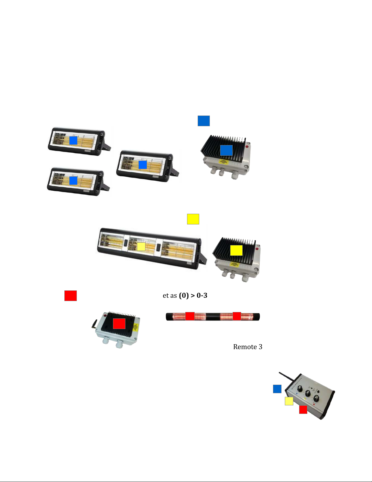
Expandable heating system using a QHVCR multiple
QHC03MR, QHC06MR QHC18MR controllers.
Using the remote 3 zone QHV R controller the area being heated can be zoned into three area's
Blue, Yellow & Red. Each zone can be controlled separately, this includes setting each zone at a
different level. There are 5 setting levels > Off – 1 (33%) - 2 (50%) - 3 (66%) - 4 (100%).
Any combination of our QH controllers can be used in the proposed zoned layout below. There
are 3kW QH 03MR, 6kW QH 06MR & 18kW QH 18MR controllers available to be used
depending on the over all number of heaters required.
Blue zone 6kW controller set a (0) > 0-1
Blue zone has 3 x 2kW heaters Total 6Kw
Yellow zone 6kW controller set as (0) > 0-2
Yellow zone
has 1 x 6kW heater
Total 6kW
Red zone 3kW controller set as (0) > 0-3
Red zone has
1 x 3kw heater
Total 3kW
Remote 3 zone QHV R controller
set as an (0) > 0
This configuration allows the heaters in the Blue zone be controlled
by the 1st dial on the remote control, setting levels at Off to 4.
The Yellow zone is controlled by the 2nd dial & the Red zone
is controlled by the 3rd dial.
For larger installations multiple controllers and heaters can be
added to each zone where required.
It is recommended that each heater should be fused with a spur. Each controller should
have a Type C MCB circuit breaker and the whole installation must have an Isolation
switch.
Page 5

Troubling shooting
1) The QH 06MR (receiver) is not working.
heck that the unit is wired correctly and follow the installation procedure on page 1.
The neon indicator should be ON to indicate the the Mains is connected correctly.
Then check that the status LED D5, the +5v LED D6 & the +12v LED D7 are all ON green.
If the status LED is Red, this indicates that there is a problem with the mains connection
to the board.
If the +5v or +12v LEDs are Red this indicates that there is a problem with the processor
chip or a power supply problem.
2) There is no communication between the QH 06MR & QHV R
The units may not be paired correctly. First determine what frequency the QHV R is set at.
The setting is marked at the back of the unit. If it's marked (0) you must check to see if the
QH 06MR is also set the same and is also marked (0). If they are different then the
controller QH 06MR will not work.
If needed you can reset the controller QH 06MR by following the Pairing instructions on
page 3.
3) Paired transmitter QHV R & receiver QH 06MR still won't communicate even when they
are both set the same. The small antenna RF P B could be the problem. heck if the small
LED flashes Red when the transmitter QHV R is turn ON & OFF. The communication is
good between the two units when the LED flashes Red. Otherwise if the LED remains ON
Green then the RF P B is faulty and needs to be replaced.
However, if the RF P B is working and the LED flashes Red but the controller QH 06MR is
still not working. The cable connection between the RF P B and the Antenna could be
faulty and may need to be replaced.
4) Yellow zone is not working !
The problem could be the receiver is set as a blue zone or red zone. If this is the case all
you have to do is re-set the right hand rotary switch to position 2. See page 3
5) ircuit Breaker M B keeps tripping when the heaters are turned ON !
Ensure that the M B is a Type where there are likely to be surges. A common fault is to
use Type B but these will always fail. Replace with Type and the problem should be
fixed.
6) If the controller does not respond to settings 3 & 4.
heck the for a loose or missing Black connector ref. J8 (TMP2) header on the printed
circuit board (P B).
Page 6

CE RoHS Technical Data
Supply voltage : Single phase 240v AC 50 Hz
Max. Load capacity : 6 kilo Watt
Input : Live (Brown) terminal #2
Neutral (Blue) terminal #3
Earth in (Grn/Yel) terminal #4
Input : PIR input trigger terminal #1
utput : Switched Live out (Brown) terminal #7
Soft start Neutral return out (Blue) terminal #6
Earth out (Grn/Yel) terminal #5
Transmission: RF 433mHz
Range : Short Antenna 40 meters *(Line of sight)
Long Antenna 100 meters *(Line of sight)
IP Rating: IP56
Dimensions : 200mm x 180mm x 120mm
Weight : 1.5 Kgs
Notes: Type C MCB circuit breakers must be used when installing this product.
It is recommended that heaters connected to this controller should be fused
individually with a fused Spur.
Tel. 01279 466 500 Email: [email protected]
Website: www.heat-outdoors.co.uk
Unit 9 Stort Valley Industrial Estate, Bishop's Stortford, Hertfordshire, CM23 2TU, UK
Other manuals for QHC18MR
1
This manual suits for next models
2
Table of contents
Other Heat Outdoors Controllers manuals


