heatco HE SERIES User manual

OEM INSTALLATION INSTRUCTIONS
HE SERIES
DUCT FURNACE
HE Series Duct Furnaces are a Recognized Furnace Component
by Intertek Testing Services (ITS / ETL)
For Indoor or Outdoor Installation
For Installation Downstream of Refrigeration Systems
This Product is intended for installation by Original Equipment Manufacturers
of Listed Heating Equipment in Duct or Cabinet mounted Applications on
Positive Pressure side of the Circulating Air Blower
The duct furnace modules covered by these instructions become a component of a
“Listed” product, subject to the guidelines of application provided in these instructions
and as designated by the Certifying Agency in the Manufacturer’s Listing Procedure
Manufactured by
Heatco Inc
50 Heatco Court
Cartersville, Ga. 30120
HE-OEM-MAN-E-2016-2
Improper installation, adjustment or alteration
can cause injury or death. Read installation,
operating and maintenance instructions
thoroughly before installing or adjusting furnace.
WARNING !

2
Table Contents
Rating Information (Rating Plate) 3
Conditions of Application 3
Duct Furnace Installation 4
Condensate Drains 4
Cabinet / Air Tunnel 5
Vestibule Enclosure 5
Combustion Air 6
Gas Supply and Piping 7, 8
Electrical Requirements 8
Venting 9
Outdoor 9
Indoor 9-12
Airflow / Turndown 13
Burner Operation, Wiring Diagrams 13
Instructions & Labels 14
Annual Inspection & Maintenance 14
HE Series Ratings 15

3
Duct Furnace Ratings
A Rating Plate is attached to the front shroud of the duct furnace to identify the model and serial number of this
product. This plate must be left attached when the furnace is installed in the product for identification purposes. The
Rating Plate contains information including gas type, maximum and minimum input rating for this furnace assembly
and application, manifold pressure to provide rated Btuh input, maximum and minimum inlet supply gas pressure,
maximum and minimum airflow requirements, output capacity and electrical ratings for this specific module.
A Nameplate / Rating Plate is also attached to the power burner housing by the burner manufacturer, indicating the
input range, gas manifold pressure and electrical ratings for the power burner. The power burners used in these duct
furnaces typically have a wide range of input settings allowing a specific burner model to be used on more than one
size duct furnace. The burner has been orificed to provide the maximum input for this duct furnace at the manifold
pressure marked on the Furnace Rating Plate attached to the front shroud. Never adjust burner for inputs
exceeding the marked furnace maximum input.
Conditions of Application
This duct furnace must be applied in accordance with the requirements of its listing as follows:
Maximum input ratings, duct and cabinet clearances to heat transfer surfaces, maximum and minimum
temperature rise and maximum and minimum airflow.
Installed on the positive side of the circulating air blower only.
Installed in a Non-Combustible Duct or Cabinet and is not designed to have any portion of the heat
exchanger exposed outside the duct or cabinet in which it is housed. The furnace heat exchanger should be
sheathed to direct airflow over the heat exchanger surfaces (See Pg.4)
Have adequate airflow within the duct or cabinet, sufficiently well distributed to limit the maximum
temperature above inlet air temperature on heat exchanger surfaces as follows:
o409 Stainless Steel 1080 oF 304 Stainless Steel 1380 oF
Specify Vent pipe the same diameter or cross-sectional area equal to flue collar or integral vent connector.
In constant volume airflow or modulating applications, burner turndown is limited to maintain the required
minimum 20 oF rise across the heat exchanger. For applications using 50% or more outside air, other
restrictions may apply. Refer to section “Airflow Consideration and Burner Turndown.
May be installed in series, provided the discharge air temperature does not exceed an average of 160 oF
above Room Temperature.
Clearances to combustibles as appropriate for the design, but in no case less than the following unless
determined by test as part of the manufacturer’s listing:
6 in. – Sides and back 2 in. – Bottom 36 in. – Top 24 in. – Front 2 in.- Vent
The equipment manufacturer shall provide adequate Installation and Operating Instructions for the completed air
handling unit to which the duct furnace is applied. The Installer/User Instructions, Gas Burner Instructions and Flame
Safeguard Instructions as well as wiring and piping diagrams provided in the information package shipped with this
duct furnace must be included with the finished product at the time of shipment. In addition, see labelling
requirements on Page 14.
WARNING
Never adjust burner for an input rate exceeding the maximum input marked on the DUCT FURNACE
rating plate located on front shroud. Damage to the furnace and hazardous operation can result.

4
Duct Furnace Installation
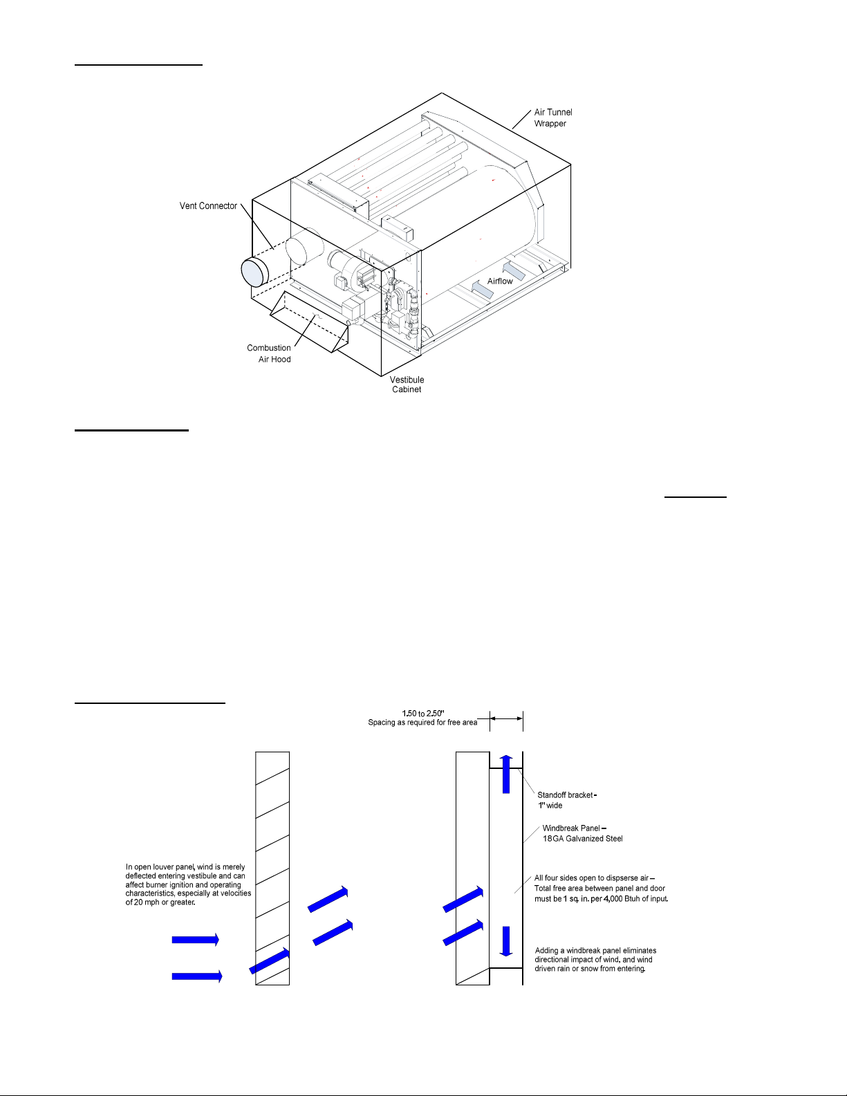
Figure 1 -Typical Installation
Locate circulating blower at least 24 inches from closest heater surface. Locate downstream filters (if used) at least
36 inches from closest heater surface.
An automatic reset High Limit Switch is provided in accordance with the listing standard to shut-off of the gas
supply to the main burners if the outlet air exceeds the allowable maximum. The switch is set at 180 oF. Do Not Set
switch to a higher temperature.
An airflow proving switch is provided to insure circulating airflow over the heat exchanger prior to burner ignition
and operation. Uncoil tubing from circulating airflow switch provided, and position open end of tube in representative
location facing the airflow.
An auxiliary manual reset temperature limit must be installed in the duct furnace module application. A manual
reset auxiliary limit prevents overheating of the furnace module in the event of a circulating air fan failure or
reverse air flow. Under these conditions the integral primary high limit would cycle the heater resulting in possible
heat build-up and damage to the heating unit.
Duct furnaces may be installed downstream of cooling systems.
Condensate drain lines must be connected if heating unit is equipped with modulating controls or if it is located
downstream of cooling section or is equipped with modulating gas controls. ½ ” NPT condensate drain fittings are
provided in each collector box. Condensate drain lines should be corrosion resistant. If Metal tubing is used, it must
have corrosion resistance at least equal to that of 304 SS. Copper tubing is not suitable for flue gas condensate.
Attach drain lines with proper pitch (1/4” per 12”) to provide positive drainage of any condensate. Free flow of any
condensate that may be present is critical to life of the heat exchanger.
Provide proper rigging to support furnace during installation into cabinet. Do not lift module by tubes or burner
housing, as damage could result.
Expansion and contraction occur during heating and cooling cycles and heat exchanger mounting employs
elongated slots for mounting bolts. Nuts and washers are used to secure heat exchanger elements to the frame in a
manner that will allow for expansion of the heat exchanger assembly within the frame. NEVER tighten nuts to
supports. Heat exchanger damage can occur.

5
Cabinet / Air Tunnel Size
Sheeting must be added to HE modules to direct airflow over the heat exchanger. See diagram below for proper
sheeting guidelines.
If the AHU cabinet is larger than the sheeted heat exchanger assembly, block off panels must be installed to prevent
circulating air from bypassing the heat exchanger.
Provide removable access panels on both upstream and downstream sides of ductwork. These openings
need to be large enough to inspect heat exchanger for leaks (i.e.. smoke or light test) and observe heat exchanger
for hot spots indicating poor air distribution.
Vestibule Enclosure
Provide an enclosed vestibule area (See Figure 2) to house and protect gas controls, burner assemblies,
combustion air fans and electrical controls. For outdoor applications this enclosure must be weathertight.
Provide access door or panels for access to burners and components. Access panels or doors to the vestibule
area should be sized and located to provide easy access for adjustment, servicing and maintenance of gas and
electrical controls.
Provide a vent connector the same size as the flue collar for attachment of vent pipe on the installed unit. All joints
in the vent connectors inside the vestibule must be sealed to prevent leakage of flue gases in the vestibule area and
into the combustion air supplied to the burners.
Permanent connection of the line voltage supply shall be made into the vestibule area on part of the assembly that
does not require movement during normal servicing and adjustment. Means shall be provided for connection of
metal clad cable or conduit housing the line-voltage supply circuit to the appliance enclosure.
Using the top of the insulated front
shroud as a guide, sheet horizontally
back to join the vertical sheeting
For optimum performance
sheet vertically from the end
of the base rail
This right to left airflow heat
exchanger is now in place in the
AHU air tunnel
Note: Insulation used for sheeting
adjacent to heat exchanger should be
rated for 850 oF. Otherwise a heat
shield with a minimum gap of 1in. must
be used for vertical sheeting
6
Figure 2 - Vestibule
Combustion Air
Air required for combustion is drawn in through the inlet of the burner fan assembly. The vestibule in which burner is
installed must have an ample supply of combustion air. Opening(s) in a panel or door (except separated
combustion systems) must be provided in the enclosure and should be sized at 1 square inch of open area per
4,000 Btuh of input.
Openings should be located to avoid recirculation of flue gases from the vent discharge into the combustion air
supply. Consideration should be given to location of air openings so that flow of air is not impeded by other features
of unit design and also to prevent blockage from snow build-up for outdoor installations.
Louvered openings may restrict free area up to 50%. If louvers are employed be sure the overall opening size is
sufficient. Additionally, for outdoor installations with louvered panels, a windbreak should be provided to prevent
accumulation of wind driven rain or snow on components. See Figure 3.
Figure 3 - Windbreak
7
Gas Supply and Piping
Installation of gas piping must conform with ANSI Z223.1 (NFPA 54) National Fuel Gas Code. In Canada,
installation must be in accordance with CAN/CGA –B149.1 for Natural gas and B149.2 for propane units.
Use a pipe sealant resistant to LP gases on gas supply connections to heater.
Properly support gas valve with back-up wrench, during installation to prevent loosening valves or damage to
burner assembly or manifold.
Supply piping must be the same size or larger than piping supplied on the burner assembly
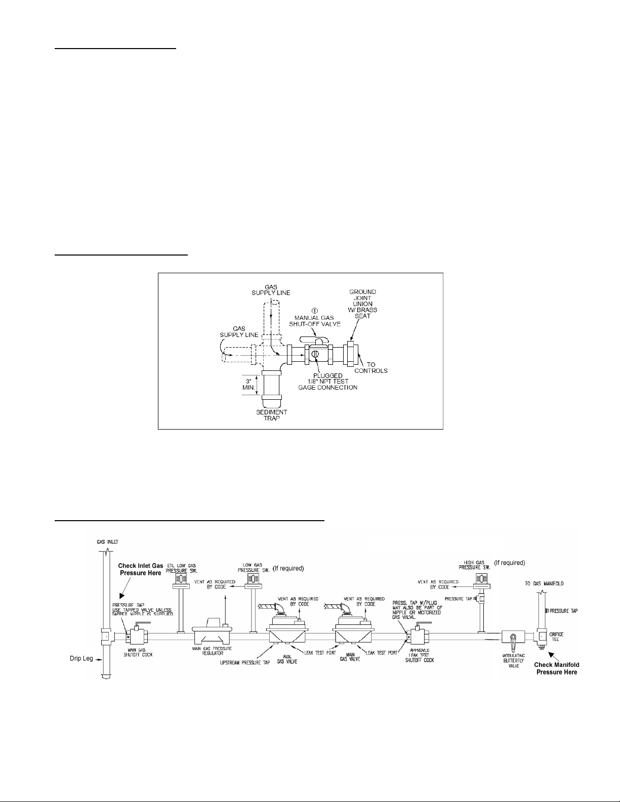
The manufacturer’s instructions must specify the use of drip leg (sediment trap) and a manual shut off valve
immediately upstream of the gas control on the heating unit. To facilitate servicing of unit, installation of a union is
recommended. (See Figure 4)
Figure 4 – Sediment Trap
Gas burners are Listed to UL Standard 295 and have valve trains that meet UL and FM requirements. Valve train
configuration depends on the burner utilized. See Figures 5 and 6 for typical gas piping and valve trains.
Figure 5- Typical Gas Piping – Power Flame Burners
Verify setting of ETL Low gas pressure switch (Power Flame burners only) is 5.0” w.c.
8
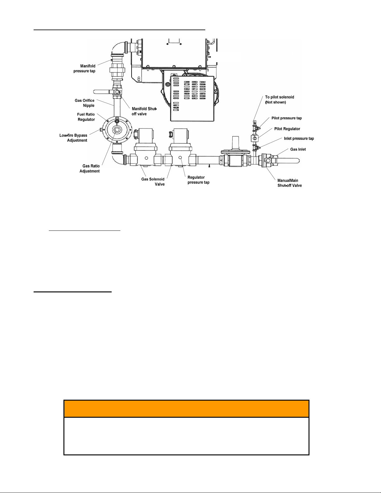
Figure 6- Typical Gas Piping – Midco V Series Burners
Prior to shipment check both the supply lines and factory piping for leaks. Apply a soap and water solution to all
joints and watch for bubbles indicating a leak. NEVER test for gas leaks with an open flame.
The duct furnace requires a minimum inlet gas pressure of 7.0 “w.c. and a maximum inlet gas pressure of 13.5”
w.c., with the furnace operating.
Instructions are provided with the power gas burner installed on furnace covering proper set-up and adjustment,
including minimum rate adjustment. These instructions must be included with the fully assembled product.
If gas pressure switches are provided, they are listed, vent limited switches and do not require vent piping to the
building exterior.
Electrical Requirements
All electrical equipment must be grounded and wired be in accordance with the National Electric Code (ANSI/NFPA
70) in the United States, and the Canadian Electric Code (CSA C22.1), in Canada. The installer / equipment
manufacturer is responsible for final compliance with these requirements.
Permanent connection of the line voltage supply shall be made in the vestibule area on part of the assembly that
does not require movement during normal servicing and adjustment. Means shall be provided for connection of
metal clad cable or conduit housing the line-voltage supply circuit to the appliance enclosure. Line voltage and
safety circuit wiring which is external to the appliance enclosure must be protected by metal clad cable or conduit.
The furnace control system requires both line voltage and low voltage circuits with correct polarity, and clean neutral
and ground. Line voltage readings between L1 and Neutral as well as L1 and Ground should be within +/- 3 volts.
Refer to the furnace rating / nameplate for electrical ratings.
WARNING !
Wiring must be in accordance with wiring diagram provided. Altering
the wiring could result in a hazard to persons and property.
If any original factory wiring must be replaced, replacement wiring
material must have a temperature rating of at least 105 oC.

9
Venting
Installation of venting system in U.S. must conform to local building codes and / or the National Fuel Gas
Code (ANSI Z223.1) or in Canada the Canadian Installation Code (CAN/CGA-B149) and the manufacturer’s
installation instructions. If venting requirements exceed these guidelines, a custom vent design may be required.
Proper venting of the heating section is important to safe and efficient operation of the duct furnace. Vent
materials are provided by others and must be of a suitable type for the Category
Outdoor Installation
1. The vent piping must be the same diameter as the integral vent connector.
2. See Figure 7 below for preferred outdoor venting configuration. The vent termination or cap must extend a
minimum of 18 inches feet above the AHU cabinet. Transition from horizontal to vertical should be made in
a “T” fitting. Provide a drain opening in the bottom of the “T” to drain condensate that may form in vent stack
during heater operation.
3. Use of B Vent is acceptable and helps reduce condensation in outdoor vent pipe runs.
Figure 7 – Outdoor Vent Installation
Indoor Installations
All duct furnaces installed indoors must be connected to a venting system to convey flue gases outside of
the heated space. Standard indoor installations use building air for combustion air supply and vent the products of
combustion outdoors through a single wall or roof penetration.
Vent pressures are positive and therefore are classified as Category III venting systems in accordance with ANSI
standards. All vent pipe joints must be sealed to prevent leakage of flue gases into the heated space. Specify use
of Category III vent materials listed to UL1738 / ULC S636 for vent pipe and fittings only. Provide a minimum
of 12 inches of straight vent pipe after the discharge connection before tee fittings or elbows.
Proper venting of the heating units is the responsibility of the installer. Vent piping is supplied by others.
EACH DUCT FURNACE MUST HAVE ITS OWN INDIVIDUAL VENT PIPE AND TERMINAL. Do not connect vent pipe to
other vent systems or a chimney. Down turned sections are not permitted in vent piping runs.
Indoor Installations require a blocked vent safety switch to shut-off burner in the event of a blockage in the vent
pipe. Specify unit for indoor installation or request switch kit.

10
Figure 8 - Standard Horizontal and Vertical Indoor Venting Arrangements
Horizontal Venting
Vertical Venting
WARN
ING
!
Indoor furnaces are equipped with a blocked vent safety switch to shut-
off gas supply to the main burner in the event that a blockage occurs in
the venting system downstream of the heater. Do not disable or bypass
this switch. Disabling switch may result in hazardous operation.
11
Table 1 – Vent Connector Size
Model
Size
Maximum
Input (Btuh)
Flue
Exhaust
Max.
Eq.
Vent
Length
(ft.)
Model
Size
Maximum
Input (Btuh)
Flue Exhaust
Max.
Eq.
Vent
Length
(ft.)
Diameter
(inch)
Diameter
(inch)
HE0250 325,000 6 60 HE1500 1,875,000 12 60
HE0320 400,000 6 60 HE1750 2,250,000 12 60
HE0400 550,000 6 60 HE2000 2,500,000 12 60
HE0500 625,000 8 60 HE2500 3,000,000 14 60
HE0750 950,000 10 60 HE3000 3,750,000 14 60
HE1000 1,250,000 10 60 HE4000 5,000,000 14 60
HE1250 1,550,000 10 60
Separated Combustion
In indoor applications where combustion air must be brought from outdoors, a two-pipe separated combustion
system may be used.
The duct furnace must be mounted with the burner section in a reasonably airtight vestibule compartment. No air
openings are to be provided in the vestibule access door or panel communicating with the heated space and sealing
grommets or gaskets must be provided for doors or access panels, gas and electrical entry points into the vestibule
to maintain a reasonably airtight seal.
Provide the following information in the Installation and Operating Instruction Manual:
1. Vent pipe must be Category III vent materials listed to UL1738 / ULC S636. Air piping may be single
wall 24-gauge galvanized pipe with joints sealed with silicone caulking or metal tape.
2. Category III vent materials must be from the same vent manufacturer. Do Not intermix vent system parts
from different vent manufacturers.
3. Separated combustion systems may not be common vented. Each heater must have its own
individual air supply and flue gas exhaust vent.
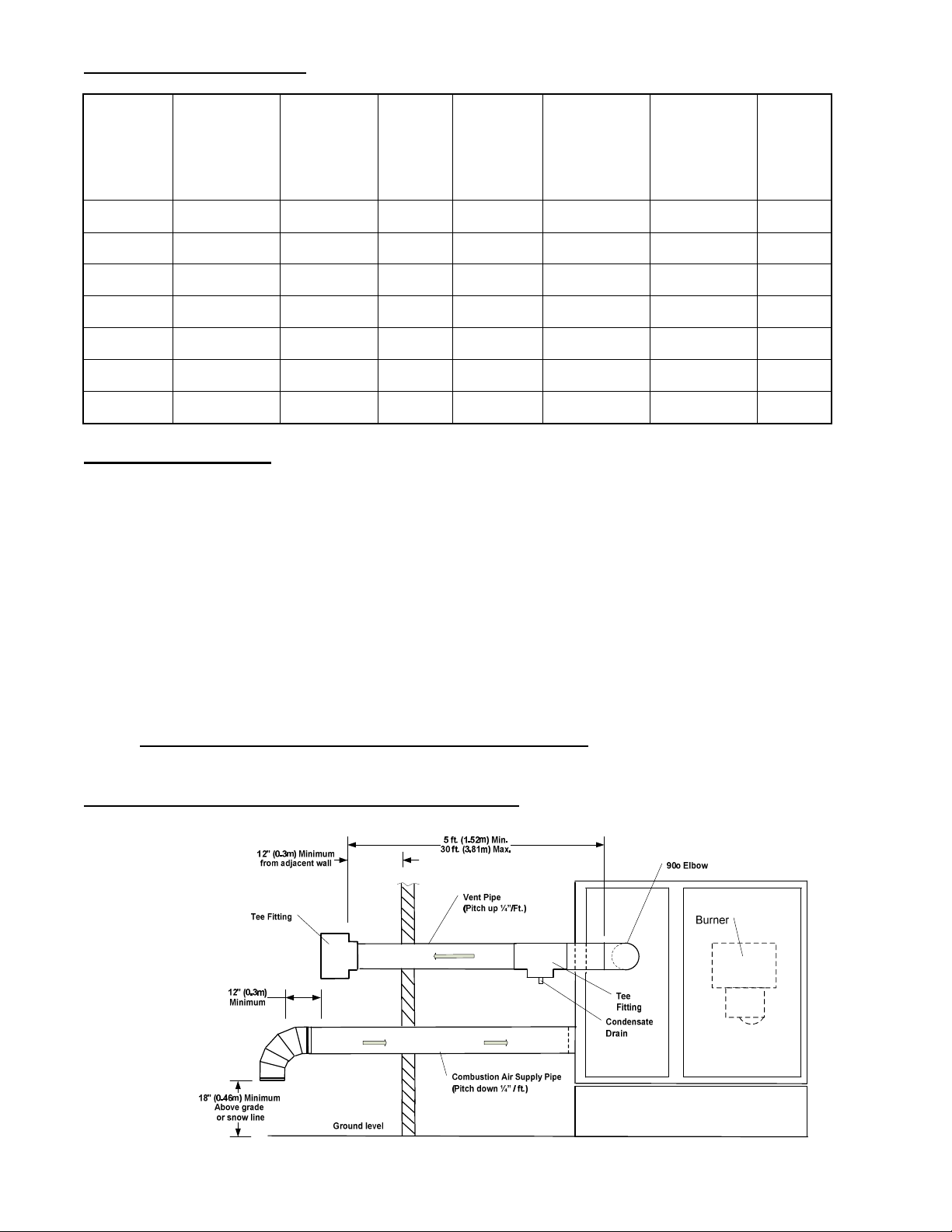
Figure 9 – Separated Combustion – Horizontal Venting

12
Alternate Vent Terminations
Vent Pipe
18" (.45m) Minimum
Combustion Air
Inlet Pipe
6 ft. (1.8m) Min.
to Adjacent Wall
or Buidliung
24" (0.6m) Min.
From adjacent
Wall or building
90o Elbow
Vent Pipe
(Pitch up ¼”/Ft.)
Condensate
Drain
Tee
Fitting
Combustion Air Supply Pipe
(Pitch down ¼” / ft.)
Listed Vent Cap
Ground level
Burner
Gas Burner
18" (0.45m) Minimum
Above grade
or snow line
12" (0.3m) Minimum
from adjacent wall
12" (0.3m)
Minimum
18" (.45m)
Minimum
5 ft. (1.52m) Min.
30 ft. (3.81m) Max.
Figure 10 – Separated Combustion – Horizontal Venting
Table 2 – Vent and Air Pipe Size
Model
Size
Maximum
Input
(Btuh)
Flue
Exhaust Air Intake
Max.
Eq.
Vent
Length
(ft.)
Model
Size
Maximum
Input
(Btuh)
Flue
Exhaust Air Intake
Max.
Eq.
Vent
Length
(ft.)
Diameter
(inch)
Diameter
(inch)
Diameter
(inch)
Diameter
(inch)
HE0250 325,000 6 6 30 HE1500 1,875,000 12 12 30
HE0320 400,000 6 6 30 HE1750 2,250,000 12 12 30
HE0400 550,000 6 6 30 HE2000 2,500,000 12 12 30
HE0500 625,000 8 8 30 HE2500 3,000,000 14 14 30
HE0750 950,000 10 10 30 HE3000 3,750,000 14 14 30
HE1000 1,250,000 10 10 30 HE4000 5,000,000 14 14 30
HE1250 1,550,000 10 10 30
13
Airflow Considerations and Burner Turndown
The HE duct furnace is a Category III appliance for non-condensing operation with a positive vent pressure.
Operating under continuous condensing conditions must be avoided.
The likelihood of condensing operation increases with:
a.) Colder return air across the heat exchanger as on units supplying a large % of return air as outside air
b.) Lower heat flow through heat exchanger, as with modulating burners operating at reduced input
c.) Higher airflow across the heat exchanger as with low temperature rise applications or constant volume
airflow while modulating burner input.
d.) Applications where heat exchanger is over-sized for actual heat requirements and unit typically runs at 50%
input rating or less.
These conditions can result in reduced heat exchanger temperatures, especially on the secondary tubes. If the tube
surfaces fall below the dew point of the flue gases passing through them, condensation of the water vapor present in
the flue gas can occur inside the tubes. This condensate is mildly corrosive and can damage heat exchanger.
If any of these conditions is expected, a bypass duct or section should be included so that proper airflow can be
maintained over the heat exchanger to provide sufficient temperature rise and avoid operating conditions where
continuous condensation occurs. Bypass duct should be sized to reduce airflow to provide at least a 20 oF rise
across the furnace, or higher as practical, to provide the desired supply air temperature and maintain flue gas
temperatures at furnace outlet of 200 oF or higher under any operating condition.
Burner Adjustment and Operation
Manufacturer’s instructions for proper set-up, adjustment and operation of the power burner installed are provided
with this furnace. Each duct furnace is test-fired at the factory to verify proper component operation. A copy of the
Test and Inspection sheet is also included.
Final adjustment must be made with duct furnace connected to the venting system. Refer to burner manufacturer
instructions provided for proper burner set-up.
A Start-up Information sheet is provided with these instructions and the Installer/User Instruction package provided.
This form must be completed at the time of start-up and adjustment and returned to validate warranty coverage.
Wiring Diagrams and Instructions
Each duct furnace is shipped with its own wiring diagram, sequence of operation and control diagnostic information
for the control system provided on the furnace as part of this OEM information package. These documents should
be retained by the air handling unit manufacturer for future reference
A separate Operating and Maintenance Instruction package is provided with each duct furnace including these
documents. This package should be included with the manufacturer’s instructions sent with the appliance.
WARNING !
The power burner provided with this furnace requires a Qualified Burner Technician
for start-up. A flue gas analyzer must be used when making adjustments to insure
proper combustion. Improper set-up may result in hazardous operation.
14
Label Requirements
The following labels are provided with the OEM package and must be affixed to the exterior of the appliance.
A Lighting and Operating label is also provided in the instruction package. This label must be attached to
the appliance in a conspicuous place preferably near the appliance control panel.
Annual Inspection and Maintenance
Provide instructions for proper maintenance and inspection of the heating system including the following:
Gas Supply
Remove the drip leg and clean any debris or liquid that may have accumulated. Re-attach drip leg and plug.
Turn off electrical supply to unit. Verify that there is no leakage from combination gas valve (no manifold
pressure) with the system at normal inlet pressure and no power to gas valve.
Burners
Burner should be inspected to verify that all components are free from damage and cleaned of any debris in
accordance with the burner manufacturer’s instructions provided.
Condensate Drains
Inspect periodically. Verify proper flow of any condensate present.
Be sure that condensate drain lines are not obstructed. Clean any debris or blockage from the line.
Ensure that freeze protection is functioning properly if provided.
Heat Exchanger / Flue Collector
The heat exchanger and collector box should be checked annually for deterioration and cracks. If any areas
are detected where leakage of flue gases could occur, the heat exchanger or collector should be replaced
before putting the unit back into operation.
Inspect condensate drain lines to insure they are not corroded or blocked. Clean or replace as necessary
Flue gas passageways should be inspected and cleared of any debris or loose foreign matter.
WARNING!
Improper installation, adjustment, alteration,
service or maintenance can cause injury or
death. Read the installation, operating and
maintenance instructions thoroughly before
installing or servicing this equipment.
Une installation, un réglage, une
modification, une réparation ou un
entretien non conforme aux normes peut
entraiiner des dommages matériels, des
blessures ou la mort. Lisez attentivement
les instructions d’installation, de
fonctionnement et d’entretien avant de faire
l’instal
l
ation ou l’entr
e
t
ien cet equipment.
AVERTISSEMENT

15
Electrical Wiring
Check wiring for loose connections or deterioration. Tighten connections and replace any wiring that is
deteriorated. Wiring materials must be replaced with wire suitable for at least 105 oC.
HE Series Ratings
Model
No.
Input
Rate Output Temp Rise Air Flow @ Min.
Duct Opening
Min. Max Min. Max.
Btuh Btuh oF oF cfm cfm
W W oC oC m3/s m3/s
HE0250 325,000 260,000 20 100 2407 12037
95,248 76198 11 56 1.14 5.68
HE320 400,000 320,000 20 100 2963 14815
117,228 93782 11 56 1.40 6.99
HE0400 550,000 440,000 20 100 4074 20370
161,189 128951 11 56 1.92 9.62
HE0500 625,000 500,000 20 100 4630 23148
183,169 146535 11 56 2.19 10.93
HE0750 950,000 760,000 20 100 7037 35185
278,417 222733 11 56 3.32 16.61
HE1000 1,250,000 1,000,000 20 100 9259 46296
366,338 293070 11 56 4.37 21.85
HE1250 1,550,000 1,240,000 20 100 11481 57407
454,259 363407 11 56 5.42 27.10
HE1500 1,875,000 1,500,000 20 100 13889 69444
549,506 439605 11 56 6.56 32.78
HE1750 2,250,000 1,800,000 20 100 16667 83333
659,408 527526 11 56 7.87 39.33
HE2000 2,500,000 2,000,000 20 100 18519 92593
732,675 586140 11 56 8.74 43.71
HE2500 3,000,000 2,400,000 20 100 22222 111111
879,210 703368 11 56 10.49 52.45
HE3000 3,750,000 3,000,000 20 100 27778 138889
1,099,013 879210 11 56 13.11 65.56
HE4000 5,000,000 4,000,000 20 100 37037 185185
1,465,350 1172280 11 56 17.48 87.41

16
(Page Left Blank)
Heatco Inc.
Cartersville, GA. 30120
Other manuals for HE SERIES
1
This manual suits for next models
13
Table of contents
Other heatco Furnace manuals


Popular Furnace manuals by other brands

Lennox
Lennox G50UH Series installation instructions

Nordyne
Nordyne SC Series installation instructions

Empire Heating Systems
Empire Heating Systems GWT-25-3 Installation instructions and owner's manual

Coleman
Coleman UGAA075BUJ installation manual

Lennox
Lennox ML195UH User's information manual

Payne
Payne PG95XAT Product data


