Heatcraft Refrigeration Products LD1C1A Administrator Guide

Stratus Multi Deck
Installation and Operations
Manual
Installation &
Operation Manual
KW-IOM-2150 April 2017 Part No. 31E02150
Contents
KW-IOM-2150 | Version 06
Models:
LD1C1A
Applications:
LEGACY
Self-Contained Spot
Merchandiser
Manual Structure 2
Part I: Introduction, Installation, Operation 2
Introduction 2
Description 2
Receipt, Preparation, Unpacking, and Installation 6
Operation 6
Technical Data 10
Dixell XR75CX Digital Controller 11
Parts List 17
Standard Warranty - Rev. January 2013 19
Appendices 22
Part II: Specication Sheets 31

2
Installation and Operation Manual
Manual Structure
This installation and operations (I&O) manual is in two parts.
Part I includes the introduction, installation, and operation of the models:
• Provides a brief description of the models within the family
• Describes the components
• Discusses the procedures on receipt
• Discusses the operation of the unit
• Contains a parts list for each model
• Contains the electrical wiring diagram(s)
• Contains the standard warranty and manual disclaimer
• Discusses other information required to operate the case
Part II consists of the specifications sheets for each model available at the Kysor/Warren website. The specification
sheet contains the models:
• Case data
• Dimensions
The KW website’s address is: http://www.kysorwarren.com
Part I. Introduction, Installation, and Operation
This is the I&O manual for the LD1C1A spot merchandiser and is part of the family of Kysor/Warren (KW) merchandisers.
Its purpose is to assist the user in the installation and operation of these merchandisers.
It supersedes the LD1C1 Spot Merchandiser Manual.
1. Introduction
The LD1C1A spot merchandiser replaces the LD1C spot merchandiser. The new version comes in five and ten foot
lengths. Performance improvements include:
• Larger capacity condensing unit provides better cooling performance (relative to the LD1C version):
• Provides a faster pulldown to steady state operation after defrost.
• Provides colder product temperatures.
• Mechanical thermostats were replaced with electronic controllers with digital temperature displays.
• Provides more consistent temperature control.
• Provides more consistent defrost control.
• Low temperature and medium temperature control settings are factory programmed.
• Customer does not have to adjust temperature settings to change from the low temperature setting to the
medium temperature setting. They only have to turn a keyed switch to make the change.
• Meets DOE 2012 and DOE 2017 energy consumption regulations.
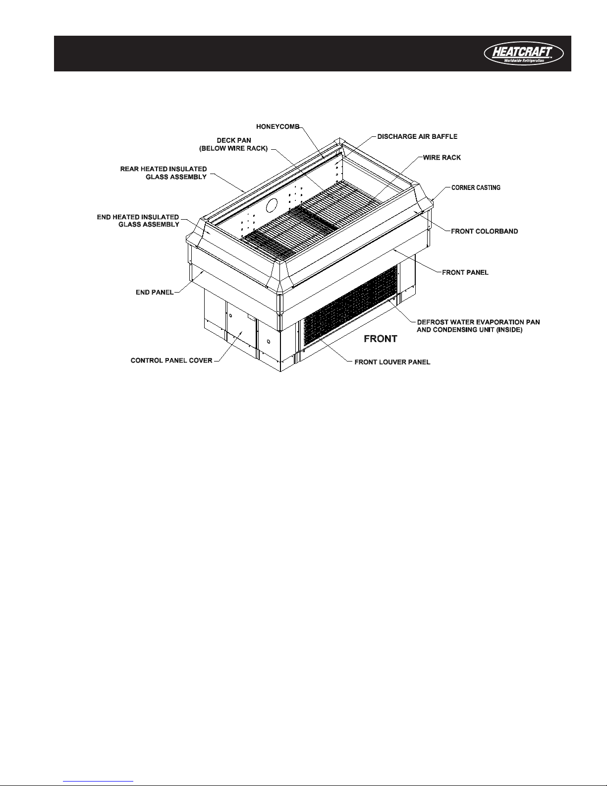
2. Description
LD1C1A spot merchandisers (Figure 2-1) are designed to merchandise packaged dairy and deli products (medium
temperature) or packaged frozen food products (low temperature). To ensure proper operation, the merchandiser
should be installed and operated according to the instructions contained in this manual. The merchandiser is de-
signed for displaying products in an air-conditioned store where the store’s ambient air is maintained at or below a
maximumallowable75°Fdrybulbtemperaturewith55%relativehumidity.HeatcraftWorldwideRefrigeration,whose
policy is one of continuous improvement, reserves the right to change at any time specifications, designs, or prices
without incurring obligation.
3
Self-Contained Spot Merchandiser
The LD1C1A is a dual temperature dairy or frozen food display merchandiser that:
• Is self-contained
• Hasanelectricdefrostheater
• Is single deck with glass handrails
• Hasadefrostwaterevaporationpan
• Is produced in either five or ten foot lengths
CAUTION: Failure to maintain store air conditions below the maximum allowable condition may result in operational
issues such as:
• Increased thermal load
• Warm product temperatures
• Coil icing
• Product frosting
• External surface condensation
NOTE: Installation and service instructions for the condensing unit are not part of this manual.
The LD1C1A-5 and LD1C1A-10 are installed individually in an area approximately 3-1/2 feet x 6 feet or 3-1/2 feet x 11
feet respectively. Adjustable glide feet are provided on each merchandiser for leveling the merchandiser. Swivel plate
mount casters with brakes are optional in lieu of glide feet. The merchandisers have continuous wrap-around heated
glass handrails.
The 5-foot model has three deck pans and the 10-foot model has six deck pans. Adjustable wire racks are available
as an option. All merchandisers are factory charged with refrigerant and tested in the factory.
NOTE: All compressor and base service valves are shipped in the open (operating) position.
Figure 2-1. Five-foot version of the LD1C1A Spot Merchandiser

4
Installation and Operation Manual
2.1. Components
Electrical
AllfieldinstalledwiringmustcomplywiththeNATIONALELECTRICALCODEANDLOCALELECTRICALCODES.
The merchandiser is provided with power cord(s) that have a male plug that is shipped loose for installation in the
store. There is/are also matching female receptacle(s) that are shipped loose. To gain access to the inside of the
electrical control panel, remove the control panel cover. Ensure that the correct input voltage is being supplied to the
merchandiser.
The power supply for each system is 4 wire 208 VAC that includes two 208 VAC hot legs, a neutral wire and a ground
wire (Figure 2-2). All 10 foot models have two separate refrigeration systems with two separate power supplies.
WARNING!
ALL MERCHANDISERS MUST BE PROPERLY GROUNDED
Ensure that the proper wire conductor size and branch circuit protection are employed on each
electrical circuit for safe operation.
Evaporator Fan Motor
The evaporator fan motor is permanently oiled for the life of the motor and requires no periodic maintenance. The fan
motor is wired according to the wiring diagram and must run continuously to circulate air through the evaporator coil
and air ducts during defrost to remove frost and ice that has accumulated during the refrigeration cycle.
Anti-Condensate Heaters
Anti-condensate heaters are installed in the merchandiser to prevent surface condensation or frost from forming
on specific areas of the merchandiser. All insulated glass assemblies contain three 3/16" thick glass panels with
two1/4"airspacesinbetweentheglasspanels.Heatisappliedontheinsidesurfaceoftheexteriorpaneofeach
insulated glass assembly. Anti-condensate heaters are energized only when the merchandiser is operated in the low
temperature mode.
Defrost Heater
A standard 115 volt defrost heater is located inside the fan plenum and is attached to the front face of the evaporator
coil. The defrost heater is designed to provide evenly distributed heat to the evaporator coil to ensure adequate
defrosting of the evaporator coil during defrost cycles. The defrost cycle is time initiated by the electronic controller
Figure 2-2. Receptacle for Four-Wire 208 VAC

5
Self-Contained Spot Merchandiser
that stops the refrigeration cycle and energizes the defrost circuit to energize the defrost heater. The defrost cycle
is terminated either by a temperature sensor connected to the electronic controller or failsafe time returning the
merchandiser into refrigeration mode. A defrost heater safety limit thermostat (Klixon) is wired in series with the
defrostheaterthatopensifthetemperatureexceeds70°F.
Expansion Valve
The expansion valve furnished with the merchandiser was selected to provide maximum coil operating efficiency.
The expansion valve superheat is preset at the factory. Should it be necessary to adjust the superheat, place a
thermocouple on the suction line near the expansion valve bulb using a plastic wire tie. Measure the suction line
pressure at the suction line service valve (Figure 2-3). Convert the suction line pressure measured at the suction line
service valve to saturated evaporator temperature using a refrigerant pressure-temperature conversion chart. The
difference between the thermocouple temperature and the saturated evaporator temperature is the superheat. (Use
average superheat when the expansion valve is hunting) Do not attempt to set the expansion valve superheat until
the merchandiser has reached steady state operating temperature. Never open or close the expansion valve more
than a 1/4 turn between adjustments and allow a minimum of 15 minutes or more between valve setting adjustments.
Superheatshouldbesetbetween6-8°F.
Refrigerant Piping
The suction line piping size is 1/2" outside diameter and the liquid line piping size is 3/8” outside diameter. The liquid
line and suction line are connected to service valves on the base of the condensing unit. All normal service except
compressor replacement can be done without removing the condensing unit.
Liquid Line / Suction Line Heat Exchanger
A liquid line / suction line heat exchanger is standard on these merchandisers. It helps increase operating efficiency
and reduces possible flood-back to compressors.
Condensing Unit
This dual temperature merchandiser incorporates a Copeland condensing unit with a KALB-015E-CAV model
Copeland compressor. The condensing unit is equipped with a preset crankcase pressure regulator set at 30 psig to
protect the compressor from overload after defrost termination and when operating in medium temperature mode.
The merchandiser uses a condensate evaporating pan with an electric heater that is used to evaporate defrost drain
water into the air. The low wattage evaporation pan heater operates to evaporate defrost drain water between defrost
cycles whenever the pan fills with water.
Refrigerant
Therefrigerationsystemcontains5poundsofR-404A(HFC)refrigerant.Iftheunitshouldrequirerecharging,the
systemmustbeevacuatedandre-chargedwith5poundsofR-404Arefrigerant.
The refrigerant charge for this merchandiser is very critical. If the merchandiser should need to be recharged, an
accuratechargingdevicemustbeused.Refrigerantshouldnotbereleasedintotheatmosphereandmustbe
reclaimed if removed from the refrigeration system.

6
Installation and Operation Manual
3. Receipt, Preparation, Unpacking and Installation
This section covers the receipt, preparation, unpacking and installation of the merchandiser.
NOTE: Read all instructions carefully before beginning installation.
3.1. Receipt
All equipment should be examined for shipping damage before and during unloading. If there is any damage:
• The carrier should be notified immediately and an inspection requested.
• The delivery receipt must note that the equipment was received damaged.
• If damage was concealed, the customer should contact the carrier immediately or no later than three days fol-
lowing delivery.
• A claim must be filed with the carrier by the consignee for all damage.
NOTE: All claims for shortages must be submitted within 10 days after receipt of shipment.
3.2. Preparation
Prepare the installation area as follows:
• Clean the area where the merchandiser is to be installed.
• Verify the area is at least 15 feet away from any outside entrances or heating and cooling outlets.
• Ensure that floor structural loading will support the merchandiser including the merchandiser contents.
• Ensurecorrectpowerisavailable.RefertomerchandiserpowerinputrequirementslocatedintheElectrical
Data section of this manual.
3.3. Unpacking
When unpacking:
• Ensure the evaporator cover is installed correctly with the deck pans installed.
• Move the merchandiser into position, install, and perform the operational checkout procedures following the
instructions in this manual.
NOTE: For shipping purposes, two compressor mounting bolt nuts (right rear and left front) have been tightened to
prevent damage to the condensing unit during shipment. THESE NUTS MUST BE LOOSENED BEFORE START UP so that the
compressor can oat freely on the supporting springs. To gain access to the compressor mounting bolt nuts, remove
the lower front louver panel and the right end cover.
3.4. Installation
• Ensure all preparation for installation, as outlined in the above paragraphs, has been fully complied with and is
complete.
• Allow a minimum of 18 inches between the rear and front of the merchandiser and store walls and/or other
merchandisers. This space reduces the possibility of surface condensation and compressor overheating.
4. Operation
Merchandise should not be placed in the merchandiser until the merchandiser is at steady state operating
temperature. The merchandiser should not be loaded with product above the load limit line located on the top of the
inside back panel. If this load limit line is exceeded, cooling performance will be adversely affected and will result in
warm product temperatures as well as increased operating costs.
Each 5 foot model merchandiser and each 5 foot section of the 10 foot model merchandiser contain two electronic
controllers used to control discharge air temperature and defrosting (two for the left 5 foot section and two for the right

7
Self-Contained Spot Merchandiser
5 foot section). The discharge air sensor is located inside the rear discharge air duct. The settings for low temperature
and medium temperature are preset in the electronic controller and no adjustment is required after connecting power
to the merchandiser.
CAUTIONS:
• Air discharge and return flues must remain open and free of debris or obstructions at all times to provide proper
refrigeration and air curtain performance.
• Do not allow any product, signs, debris, etc., to block return air grills.
• Do not use any non-approved shelving, display racks, or any accessory that could disrupt air curtain perfor-
mance.
NOTE: Electric defrost is standard on these models and evaporator fans run continuously.
4.1. Cleaning
As a general rule, always use mild soap and water to clean the merchandiser. Special precautions must be taken
when cleaning some components of the merchandiser.
Exterior surfaces should be cleaned with warm water and mild soap to protect and maintain the finish. Do not use
cleaners containing abrasive materials or ammonia that will scratch or dull the finish. The waste outlet should be
flushed with water following each cleaning.
Interior surfaces may be cleaned with most mild soap formulas, ammonia based cleaners, and sanitizing solutions
with no harm to the surface.
WARNING!
ALWAYS DISCONNECT POWER DURING THE CLEANING PROCESS. CLEANING THE
MERCHANDISER WITH ELECTRICAL POWER APPLIED IS A SHOCK HAZARD THAT MAY CAUSE
SERIOUS INJURY OR DEATH.
CAUTION:DONOTUSEHOTWATERONCOLDGLASSSURFACES.Thiscouldcausetheglasstoshatterand
resultinpersonalinjury.Glassfrontsandendsshouldbewarmbeforeapplyinghotwater.
Do not use materials or methods listed below to clean the merchandiser. The warranty will be voided if these products
or cleaning methods are used that causes rust to form on the stainless steel surfaces or any other parts of the
equipment.
• On unpainted stainless steel surfaces (they may cause rust to form), products containing:
• Chlorine
• Chloride ion
• Any cleaner containing bleach
• On any interior surfaces because the surface may become damaged:
• Solvents
• Oils
• Acidic-based cleaners
• Abrasive cleaners and scouring pads because these will mar the finish
• Steam or high pressure systems to clean the merchandiser because seals may be broken resulting in leaks
To ensure minimum maintenance cost, the merchandiser should be emptied and thoroughly cleaned every three
months. The exterior should be cleaned weekly. The waste outlet should also be checked and cleaned weekly.
Follow the previous general cleaning of the interior and exterior parts. Do not use a water hose to clean the
evaporator or tub of the merchandiser.

8
Installation and Operation Manual
CAUTIONS:
DO NOT FLUSH THE MERCHANDISER WITH WATER. This merchandiser is not connected to a drain system and
has a defrost water evaporating pan with only a limited volume capacity.
The merchandiser should have at least 18” clearance from any wall or other obstruction in order to operate properly.
NOTE: Do not stack anything in front of the intake or exhaust louvers that may block airow on the merchandiser. Self-
contained merchandisers draw in air from the rear and discharge air toward the front. Blocking airow to the louvers
will cause the merchandiser to overheat and shut down.
Cleaning Condensing Units
Once a month, use a vacuum cleaner to remove any lint or other debris that may have collected on the entering air
side of the condenser coil.
Cleaning the Honeycomb
The honeycomb should be cleaned every 6-8 months, depending on store conditions. The honeycomb may be
cleaned with a vacuum cleaner or may be removed and be washed with soap and water. The honeycomb must be
completely dry before reinstalling it on the merchandiser if cleaned with soap and water.
4.2. Electrical Connections
All field connections are made inside the electrical control panel. Ensure that the proper power supply and voltage are
supplied to the merchandiser. Check the merchandiser data plate for the required input voltage. Field wiring must be
installed in accordance with local and national electrical codes. The electrical control panel is located:
• For the 5 foot model merchandiser, at the left end of the merchandiser.
• For the 10 foot model merchandiser, at each end of the merchandiser for each refrigeration system.
WARNINGS!
ALL MERCHANDISERS MUST BE PROPERLY GROUNDED.
ENSURE KICK PLATES DO NOT COME IN CONTACT WITH THE MERCHANDISER ELECTRICAL
WIRING. LIVE ELECTRICAL WIRING THAT COMES IN CONTACT WITH THE MERCHANDISER IS A
SHOCK HAZARD THAT MAY CAUSE SEVERE INJURY OR DEATH BY ELECTROCUTION.
ALWAYS DISCONNECT ELECTRICAL POWER AT THE MAIN DISCONNECT WHEN SERVICING
OR REPLACING ANY ELECTRICAL COMPONENT. THIS INCLUDES, BUT IS NOT LIMITED TO
COMPONENTS INCLUDING FANS, HEATERS AND CONTROLLERS. FAILURE TO DISCONNECT
ELECTRICAL POWER MAY RESULT IN PERSONAL INJURY OR DEATH.
Installing the Power Cord
There are two methods to field-install the power cord:
• The power cord exits through the base-end panel of the merchandiser
• The power cord exits through the bottom of the merchandiser base
Installing the Power Cord to Exit the Base-End Panel of the Merchandiser
The steps below and Figure 4-1 illustrate the correct method to field-install the power cord so that it exits at the base-
end panel.

9
Self-Contained Spot Merchandiser
# Installation of Power Cord to Exit the Base-End Panel of the Merchandiser
1Install the cordgrip into the hole in the base end panel of the merchandiser.
2
Routethepowercordthroughthecordgripinstalledinthebaseendpanelandintothecontrolpanelthroughthe
hole located in the bottom right hand side of the control panel. Do not tighten the cordgrip until the power cord
wire conductors have been connected into the circuit breaker and terminal board.
3Connect the color-coded power cord wire conductors into the circuit breaker, terminal board and ground terminal
as shown on the merchandiser wiring diagram.
4Once the wire conductors have been connected, leave enough slack in the power cord inside the control panel
so that it is not stretched tight.
5Tighten the cordgrip around the power cord so that the power cord cannot be moved inside the cordgrip.
Installing the Power Cord to Exit the Bottom of the Merchandiser
The steps below and Figure 4-2 illustrate the correct method to field-install the power cord so that it exits at the
bottom of the merchandiser.
# Installation of Power Cord to Exit the Bottom of the Merchandiser
1Install the cordgrip into the hole in the bottom of the base of the merchandiser inside the control panel.
2
Routethepowercordthroughthecordgripintothecontrolpanelfromtheundersideofthemerchandiserbase.
Do not tighten the cordgrip until the power cord wire conductors have been connected into the circuit breaker
and terminal board.
3Connect the color-coded power cord wire conductors into the circuit breaker, terminal block and ground terminal
as shown on the merchandiser wiring diagram.
4Once the wire conductors have been connected, leave enough slack in the power cord inside the control panel
so that it is not stretched tight.
5Tighten the cordgrip around the power cord so that the power cord cannot be moved inside the cordgrip.
Figure 4-1. Power cord installation to exit at the base-end panel of merchandiser

10
Installation and Operation Manual
5. Technical Data
This I&O manual is in two parts: Technical data listed in the LD1C1A specification sheet
The technical data for the LD1C1A merchandiser is located on the unit’s specification sheet titled:
LD1C1A – Legacy Self-Contained
Issue date: 06/13/2016
5.1. Specication Sheet
The data on the specification sheet includes:
• Merchandising Data
• Electrical Data
• RefrigerationData
• Defrost Data
• Dimensional Data
• Data plate Data
Specication sheets can be downloaded at www.kysorwarren.com
Or contact:
Technical Sales Support
Kysor/Warren
5201 Transport Blvd
Columbus,GA31907
800-866-5596phone
706-568-8990fax
Figure 4-2. Power Cord Installation Exiting the Bottom of Merchandiser Base
11
Self-Contained Spot Merchandiser
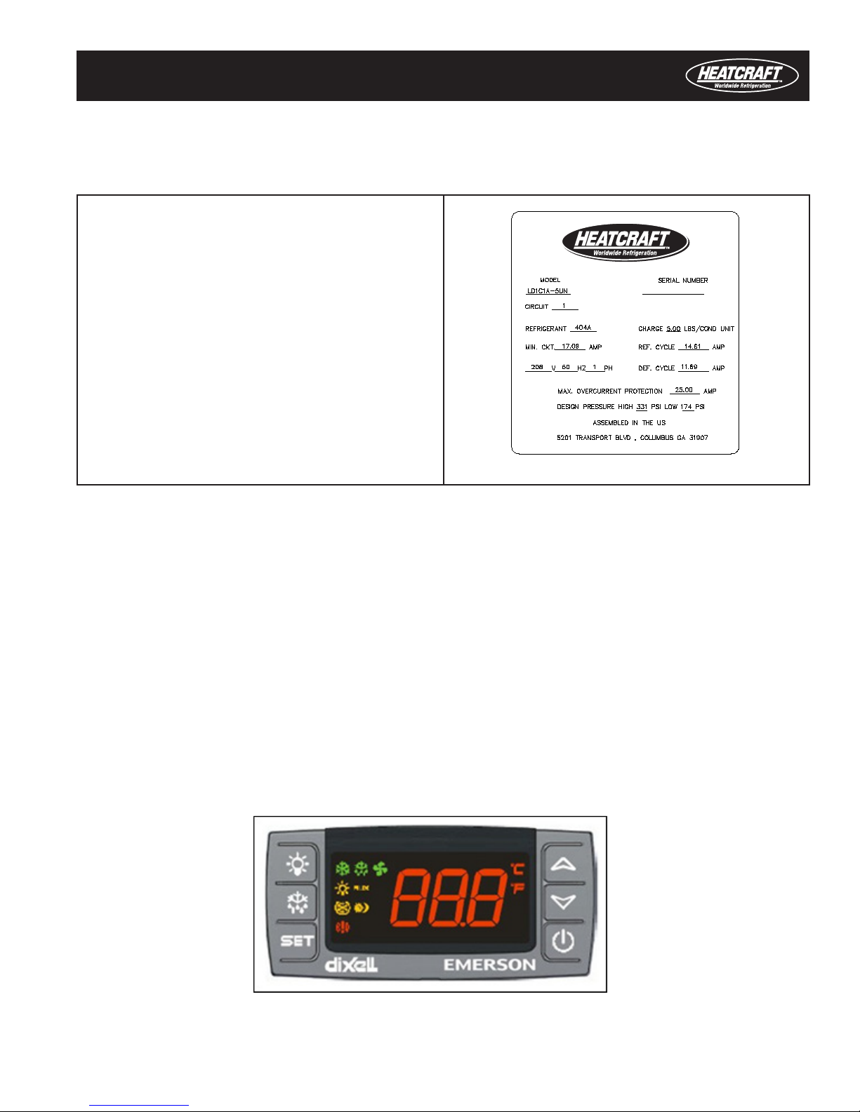
5.2. Data Plate
Figure 5-1 shows a sample data plate for an LD1C1A-5 Spot Merchandiser.
Data on the plate includes:
• Model
• Serial number
• Circuit number
• Refrigerant
• Charge
• Minimum Circuit Ampacity (MIN CKT)
• Input voltage, frequency and phase
• Refrigerationcyclecurrent
• Defrost cycle current
• Maximum overcurrent protection
• Highsideandlowsidedesignpressures
6. Dixell XR75CX Digital Controller
TheLD1C1ASpotMerchandisersareelectronicallycontrolledbyDixellXR75CXcontrollers.Each5foot
merchandiser or 5 foot module of the 10 foot model merchandiser is controlled by two of these controllers. One
controller is used for the low temperature application and the other is used for the medium temperature application.
TheDixellXR75CXcontrolleris:
• Microprocessor based
• Suitable for applications on medium or low temperature refrigeration units
• Uses two relay outputs to control:
• Compressor
• Defrost
6.1. Controller Front Panel Display
• Figure 6-1 shows the front panel of the controller
• Table 6-1 shows the keys and functions found on the controller front panel
• Table 6-2 displays the meaning of the icons within the display
Figure 5-1. Data Plate
Figure 6-1. Digital Controller Front Panel

12
Installation and Operation Manual
There are 6 keys on the control front panel display. Table 6-1 explains their meaning.
Key Function Key Function
Switches the light ON and OFF, if oA1 = Lig
Press the UP-arrow key to see the
MAX stored temperature, to browse the
parameter codes in programming mode,
or to increase the displayed temperature
value.
Starts a manual defrost
Press the DOWN arrow key to see the
MIN temperature, to browse the parameter
codes in programming mode, or to
decrease the displayed temperature value.
Press to display target setpoint, to select a
parameter in programming mode, or to con-
firm an operation
Switches the device ON and OFF, if onF
= oFF
Locks/Unlocks the keyboard Returnstoroomtemperaturedisplay
Enter programming mode
Each LED icon and its mode are described in Table 6-2.
Icon Mode Mode Icon Mode Mode
On Compressor enabled On Defrost enabled
Flashing Anti-short cycle delay enabled Flashing Drip time in progress
On Fans enabled On Measurementunitincentigrade(°C)
orFahrenheit(°F)
Flashing Fans delay after defrost in progress Flashing Programming phase
ON An alarm is occurring ON Light On
ON Energy saving enabled ON Auxiliary relay ON
ON Energy saving enabled
6.2. Common User Operations
This section covers common user operations. Common user operations include:
• Changing a setpoint value
• Changing a parameter value
• Moving parameters to and from the user level and hidden menu
• Starting a manual defrost
• Viewing the minimum and maximum temperatures
Table 6-1. Front Panel Keys and Functions
Table 6-2. Icons and Their Meanings

13
Self-Contained Spot Merchandiser
• Alarms
• Silencing an alarm
• Alarm recovery
Changing a Setpoint Value
Use the following steps to change a setpoint value. See Appendix A for the list of default settings and Appendix C for
the factory settings.
# Changing a Setpoint Value
1 Press and hold the SET button for more than 2 seconds to change the setpoint value.
2Thevalueofthesetpointwillbedisplayedandthe°Cor°Findicatorwillstartblinking.
3 To change the setpoint value, press the UP or DOWN buttons within 10 seconds
4 To memorize the new setpoint value, press the SET key again or wait 10 seconds.
Changing a Parameter Value
Use the following steps to change a parameter value. See Appendix B for the list of parameters.
# Changing a Parameter Value
1EntertheProgrammingmodebypressingtheSET+DOWNbuttonsfor3seconds(the°Cor°FLEDwillstart
blinking).
2 Select the required parameter. Press the SET button to display its value.
3 Use the UP or DOWN buttons to change its value.
4 Press SET to store the new value and move to the next parameter.
5 To exit: Press the SET + UP buttons or wait 15 seconds without pressing a key.
Assigning Parameters to the User or First Level
EachparameterpresentintheHiddenMenu(Pr2)canbemovedintotheuserlevel(Pr1)bypressingSET+DOWN
buttons.Ifaparameterispartoftheuserlevel,whenitappearsintheHiddenMenu,thedecimalpointwillbe
illuminated.
Starting a Manual Defrost
Press and hold the DEF key for more than two seconds to start a manual defrost.
Alarms
There are two types of alarms: serious and generic. Both will signal after a time delay (digital input alarm delay, or
did).
• Serious alarm. When the digital input is activated:
• The unit will wait for time delay before signaling the CA alarm message.
• The relay outputs are switched OFF.
• The alarm will stop as soon as the digital input is deactivated.
• Generic alarm: When the digital input is activated:
• the unit will wait for did time delay before signaling the EAL alarm message
• The outputs status does not change
• The alarm stops just after the digital input is de-activated.

14
Installation and Operation Manual
Table 6-3 displays the alarm message, cause, and outputs.
Message Cause Outputs
P1 Roomprobefailure Compressor output acc. to par. Con and CoF
P2 Evaporator probe failure Defrost end is timed
P3 Third probe failure Outputs unchanged
P4 Fourth probe failure Outputs unchanged
HA Maximum temperature alarm Outputs unchanged.
LA Minimum temperature alarm Outputs unchanged.
HA2 Condenser high temperature It depends on the AC2 parameter
LA2 Condenser low temperature It depends on the bLL parameter
dA Door open Compressor restarts
EA External alarm Output unchanged.
CA Serious external alarm (i2F=bAL) All outputs OFF.
CA Pressure switch alarm (i2F=PAL) All outputs OFF
rtF Realtimeclockboardfailure Alarm output ON; Other outputs unchanged; Defrosts
according to par. idF. Contact the service.
Silencing an Alarm
To silence an alarm:
• If tbA = Y, press any key to silence the buzzer and the relay.
• If tbA = n, press any key to silence the buzzer. The alarm relay however, is still ON until the alarm condition
recovers.
Alarm Recovery
Probe alarms (P1, P2, P3, and P4) start some seconds after the fault in the related probe. Probe alarms
automatically stop after a short delay once the probe restarts normal operation. Check connections before replacing a
probe.
Temperature alarms(HA,LA,HA2,andLA2)automaticallystopassoonasthetemperaturereturnstonormal
values.
External alarms (CA-serious and EA) recover as soon as the digital input is disabled.
The pressure switch alarm, CA, recovers only by switching OFF and ON the device
Viewing the Minimum and Maximum Temperatures
See Table 6-4 for instructions to:
• View the minimum temperature
• View the maximum temperature
• Resettheminimumandmaximumtemperatures
# View and Reset Minimum and Maximum Temperatures
View Minimum Temperature
1 Press and release the DOWN button.
2 The Lo message will be displayed followed by the minimum temperature recorded.
Table 6-3. Alarm Codes, Causes, and Outputs

15
Self-Contained Spot Merchandiser
3 To restore the normal display, press the DOWN button again or wait five seconds.
View Maximum Temperature
1 Press and release the UP button.
2 The Hi message will be displayed followed by the maximum temperature recorded.
3 To restore the normal display, press the UP button again or wait five seconds.
Reset the Maximum and Minimum Temperatures
1Press and hold the SET button for more than 3 seconds while the maximum or minimum temperature is dis-
played (rSt message will be displayed).
2After confirming the operation, the rSt message will start blinking and then the normal temperature will be
displayed.
6.3. Control Settings
The unique settings listed below in Table 6-5 are for the low temperature controller. The low temperature controller is
located inside the control panel on the left side.
Label Name Range Default Level Setting
SEt Setpoint LS to US -5.0 --- -20
rtc* Realtimeclockmenu - - Pr1 -
Hy Differential 1to255°F 2.0 Pr1 5
CCS Setpoint for continuous cycle -67to302°F -5 Pr2 -20
* Indicates parameters that are used when the real-time clock feature is included on the controller. The current controller does not
have this feature.
Unique settings listed below in Table 6-6 are for the medium temperature controller. The medium temperature
controller is located inside the control panel on the right side.
Label Name Range Default Level Setting
SEt Setpoint LS to US -5.0 --- 14
rtc* Realtimeclockmenu - - Pr1 -
Hy Differential 1to255°F 2.0 Pr1 18
CCS Setpoint for continuous cycle -67to302°F -5 Pr2 14
* Indicates parameters that are used when the real-time clock feature is included on the controller. The current controller does not
have this feature.
Table 6-4. Viewing and Resetting Maximum and Minimum Temperatures
Table 6-5. Unique low temperature controller settings
Table 6-6. Unique medium temperature controller settings
16
Installation and Operation Manual
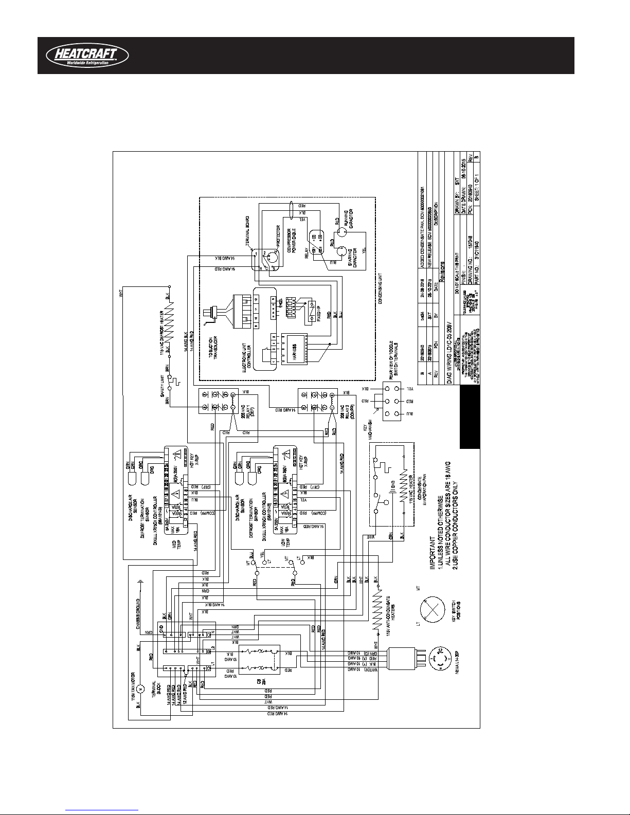
6.4. Wiring Diagram
Figure 6-2 shows the wiring diagram for the LD1C1A-5 Spot Merchandiser.
Figure 6-2. Wiring Diagram for the LD1C1A-5 Spot Merchandiser

17
Self-Contained Spot Merchandiser
7. Parts List
Figure 7-1 shows the major components of the five foot LD1C1A spot merchandiser and Table 7-1 is the parts list.
Table 7-1 provides a list of parts for the LD1C1A merchandisers.
Description Part Number
Evaporator Fan Motor (115 VAC) 09A10131
Evaporator Fan Blade 09B10013
Expansion Valve 03A25203
DischargeAirHoneycomb 13A15020 (White)
13A15056 (Black)
ElectricDefrostHeater(115VAC) 10K10117
RearHandrailAnti-condensateHeater(115VAC) 10K12324
RearColorbandAnti-condensateHeater(115VAC) 10K12326
FrontHandrailAnti-condensateHeater(115VAC) 10K12323
EndHandrailAnti-condensateHeater(115VAC) 10K12327
BottomWireRacks 28G19227(White)
28G19658(Black)
CrankcasePressureRegulator 03E10260
Liquid Line Filter Drier 05B10054
LiquidLineSightGlass 06F10057
Electronic Controller (208 VAC) 08A10143
GlideFeet 18J10024
Plate Swivel Casters 17B10014
Drain Trap Assembly 18H13028
Figure 7-1. Isometric View of LD1C1A–5 Spot Merchandiser
18
Installation and Operation Manual
Upper Corner Casting 16F10078 (Brushed SS)
16F10061 (Bright SS)
Evaporator Coil 05A20114
EndHeatedInsulatedGlassAssembly(115VAC) 14D11042
5’Front/RearHeatedInsulatedGlassAssembly(115VAC) 14D11043
10’Front/RearHeatedInsulatedGlassAssembly(115VAC) 14D11101(LH)
14D11102(RH)
ReturnAirProductFence 28G13064(White)
28G13136(Black)
Deck Pan 54N18206 (Unpainted)
54N18391(Painted)
Defrost Water Evaporating Pan Assembly 28H12044
Front/RearLouverPanel 51X16344
Electrical Control Panel Cover 54U22679
Condensing Unit (208 VAC) (EJAL-A102-CAV-021) (208 VAC) 01F10015
NOTE: Standard parts are provided in the parts lists. Merchandisers may be equipped with specialty parts that were
incorporated into the merchandiser(s) at the time it was manufactured. It is important to have the merchandiser serial
number when contacting Heatcraft Worldwide Refrigeration for replacement parts.
Table 7-1. LD1C1A Parts List

19
Self-Contained Spot Merchandiser
8. Standard Warranty - Rev. January 2013
Seller warrants to its direct purchasers that Products, including Service Parts, shall be of a merchantable quality,
free of defects in material or workmanship, under normal use and service for a period of one (1) year from date of
original equipment start-up, or eighteen (18) months from date of shipment by Seller, whichever first occurs. This
warranty runs to only the original purchaser of equipment or part. Any Products covered by this warranty found to
Seller’s satisfaction to be defective upon examination at Seller’s factory will at Seller’s option, be repaired or replaced
and returned to Buyer via lowest common carrier FOB seller’s point of shipment. This is buyer’s sole and exclusive
remedy and, except as provided in the next sentence, seller’s sole and exclusive liability in connection with the
warranty. Or Seller may at its option grant Buyer a credit for the purchase price of the defective Product. Buyer must
prepay all costs for transportation of Products to Seller’s factory.
Seller shall have no liability for expenses incurred for repairs made by Buyer except by prior, written authorization.
AnyclaimunderthiswarrantyshallbemadetoSellerinwritingwithinthewarrantyperiodspecifiedabove–otherwise
such claim shall be deemed waived. Seller shall have no warranty obligation whatsoever if its products have been
subjected to alteration, misuse, negligence, free chemicals in system, corrosive atmosphere, accident, or if operation
is contrary to Seller’s or manufacturer’s recommendations, or if the serial number has been altered, defaced, or
removed.
THISWARRANTYISINLIEUOFALLOTHERWARRANTIES,EXPRESSED,IMPLIEDORSTATUTORY,
INCLUDING,BUTNOTLIMITEDTOANYWARRANTYOFMERCHANTABILITYORFITNESS,ANDALLOTHER
OBLIGATIONSORLIABILITIESOFSELLERAREHEREBYDISCLAIMED.
Additional Warranties:
The Standard Warranty specified above applies to all Products and Service Parts unless modified by the following:
THERMO-FLEX™ORFLOATINGTUBETMDESIGNCOIL
SellerwarrantstheThermo-Flex/FloatingTubeDesignCoilofthe“BM”,“BH”,“CM”,“CH”,“HM”,“HH”,“MM”,“ML”
or“LH”seriesofUnitCoolers;coilsectionofthe“BLV”,“BDVS”,“BBV”,“JLD”,JDDS”,“JBD”,“BDT”,“BDN”,“BDS”,
“BDB”,“BZT”,“BZN”,“BZS”,“BZB”“CDD”,“CDDS”,“CDT”,“CDN”,“CDS”,“CZT”,“CZN”,“CZS”,“HDD”,“HDDS”,
“HDT”,“HDN”,“HDS”,“HZT”,“HZN”,“HZS”,“LDV”,“LDVS”,“LDD”,“LDDS”,“LDT”,“LDN”,“LDS”,“LZT”,“LZN”,“LZS”
condensingunits;andcoilsectionofthe“BN”,“CN”,“HN”or“LN”modelsofAir-cooledCondensersforaperiodof
five (5) years from shipping date, in the event of any documented and verified (by Seller’s representative) leaks in the
coil tubes containing refrigerant at the point of and caused by tube contact with the end or center coil support sheets.
Seller will also reimburse the replacement cost of lost refrigerant for a period of five years from the date of shipment
from leaks specifically caused by the reasons stated above. The replacement cost will be limited to one full system
charge. The warranty specifically excludes leaks at header and weld joints, split tubes or leaks caused by failure to
operate the product in accordance with published guidelines for operation and installation of equipment. The cost
of replacement refrigerant will be limited to Seller’s indexed nationwide average of refrigerant cost per pound. The
warranty excludes any fines/fees related to refrigerant leaks.
Air-cooledCONDENSERS“BN”,“CN,“HN”,“LN”or“NRG”Models”
SellerwarrantsAir-cooledCondensers“BN”,“CN,“HN”,“LN”or“NRG”Models”foraperiodoftwo(2)yearsfromdate
of original installation, or 30 months from the date of shipment by Seller, whichever first occurs.
Optional EC Condenser Fan Motors EC Motors
Seven (7) Blade motor assemblies - for a period of four (4) years from date of original installation, or fifty-four (54)
months from date of shipment by Seller, whichever first occurs.
Five (5) Blade motor assemblies - for a period of three (3) years from date of original installation, or forty-two (42)
months from date of shipment by Seller, whichever first occurs.

20
Installation and Operation Manual
Unit Cooler EC Fan Motors
Seller warrants EC Motors (made by McMillan) for a period of two (2) years from date of original installation, or thirty
(30) months from date of shipment by Seller, whichever first occurs.
BeaconII™CONTROLSYSTEMS
SellerwarrantstheBeaconII™ControlSystemforaperiodofthree(3)yearsfromthedateoforiginalinstallation,or
forty-two (42) months from the date of shipment by Seller, whichever first occurs.
PRO3PACKAGEDREFRIGERATIONSYSTEM
SellerwarrantsthePRO3PackagedRefrigerationSystemforaperiodoftwo(2)yearsfromdateoforiginal
installation, or thirty (30) months from date of shipment by Seller, whichever first occurs.
HYPERCORE™MicrochannelCoil
SellerwarrantstheHypercoreTMMicrochannelCondenserCoilforaperiodoftwo(2)yearsfromdateoforiginal
installation, or thirty (30) months from date of shipment by Seller, whichever first occurs.
SMARTDEFROSTKIT™
Seller warrants the Smart Defrost KitTM for a period of two (2) years from date of original installation, or thirty months
from date of shipment by Seller, whichever first occurs.
MOTORCOMPRESSORS
Motor compressor replacements or exchanges shall be made through the nearest authorized wholesaler of the
motor compressor manufacturer (not at Seller’s factory) and no freight shall be allowed for transportation of the motor
compressor to and from the wholesaler. The replacement motor compressor shall be identical to the model of the
motor compressor being replaced. Additional charges which may be incurred throughout the substitution of other
than identical replacements are not covered by this warranty. An optional, non-assignable, three (3) or four (4) year
extended compressor warranty may be purchased within the boundaries of the United States of America, its territories
and possessions, and Canada. With this extended compressor warranty, re- placements are administered by an
authorizedcompressordistributoronly.Replacementswithinthefirstyearofthewarrantyareavailablethroughthe
distributor; the second through fifth years, the purchaser must submit a proof-of-purchase of a compressor and supply
ittoHeatcraftWarrantyClaimsforreimbursement.
THIS WARRANTY SHALL NOT APPLY:
1. Glassisnotguaranteedagainstbreakage.Ifthismerchandiserisequippedwithaglazingassemblycarrying
the manufacturer’s brand name (Thermopane, Twindow, etc.), the manufacturer’s glazing warranty in effect at
the time of this shipment is extended to that assembly.
2. BULBS: Light bulbs, fluorescent lamp tubes and LEDs are not covered by any warranty for length of life or for
any type of breakage.
3. To the condensing unit used with refrigerated equipment unless same was sold and shipped by Seller
4. Whenthisequipmentoranypartthereofisdamagedbyaccident,fire,flood,actofGod,alteration,abuse,
misuse, tampering, when the original model and serial number plate has been altered, de- faced, or removed
or used other than the recommended application by Seller.
5. When this equipment or any part thereof is subject to operation on low, high or improper voltages. Low and
highvoltageisdefinedasmorethana5%dropbelowor10%higherthannameplatevoltageratings.
NOTE: Proper eld supply voltage to the equipment is the responsibility of the owner (end user).
6. To damage caused by overloading shelves or wire racks beyond the specified weight limits. The maxi- mum
weight limit for Seller’s standard shelves and wire racks is 30lbs per square foot.
7. When this equipment or any part thereof is damaged, or when operation is impaired, due to failure to follow
installation manual.
NOTE: Proper installation is the responsibility of the installer, owner (end user).
8. Operational issues caused by ambient environmental conditions outside of the specified limits. Seller’s indoor
equipment is specified to operate in a conditioned ambient environment not to exceed 75 degrees Fahrenheit
or55%relativehumidity.
NOTE: Providing specied ambient environmental conditions are the responsibility of the owner (end user).
Table of contents
Popular Merchandiser manuals by other brands


Hussmann
Hussmann IMPACT RLNIE Technical data sheet

Igloo
Igloo SAMOS DEEP Series Assembly instructions

Alto-Shaam
Alto-Shaam AR-7H ELECTRONIC CONTROL Brochure & specs

Turboair
Turboair TOM-40M Series Installation and operation manual

Hussmann
Hussmann IMPACT LWUG Technical data sheet

EPTA
EPTA iarp Grandlux 200 Use and maintenance


