NFX, NFSX, NCSX,
NFSGX, NCSGX
Page 8 November, 2007
toggle switch is flipped, the solenoid closes
directing the flow through the EPR valve. If
the EPR valve is set for 48 psig, the evapora-
tor will see a coil temperature of 12°F and will
operate at a discharge air temperature of
about 22°F.
When gas defrost is used, an additional
check valve is mounted around the EPR valve
to allow reverse flow for the defrosting gas.
A fan delay is also connected with gas defrost
to cycle the fans off, but only during the
medium temperature mode.
Electrical Procedures
Electrical Considerations
CAUTION
Make sure all electrical connections are
tight. This prevents burning of electrical
terminals and/or premature component
failure.
NOTE
The raceway houses the electrical wiring
and components for the case. All raceway
covers will be shipped loose.
Case Fan Circuit
This circuit is to be supplied by an uninter-
rupted, protected 120V circuit. The case fan
circuit is not cycled, except when equipped
for gas defrost. On gas defrost cases the fan
circuit is controlled by a 50/40 klixon when
used for medium temperatures.
NOTE
With gas defrost, the fans will not start
until the coil temperature reaches 40°F at
the fan delay klixon.
Anti-Sweat Circuit
All cases have at least one anti-sweat heater
in each discharge air grid and return air grid.
Cases with front glass have an additional
anti-sweat heater under the glass retainer.
Anti-sweat heaters are wired directly to the
main power supply so they can operate at
all times.
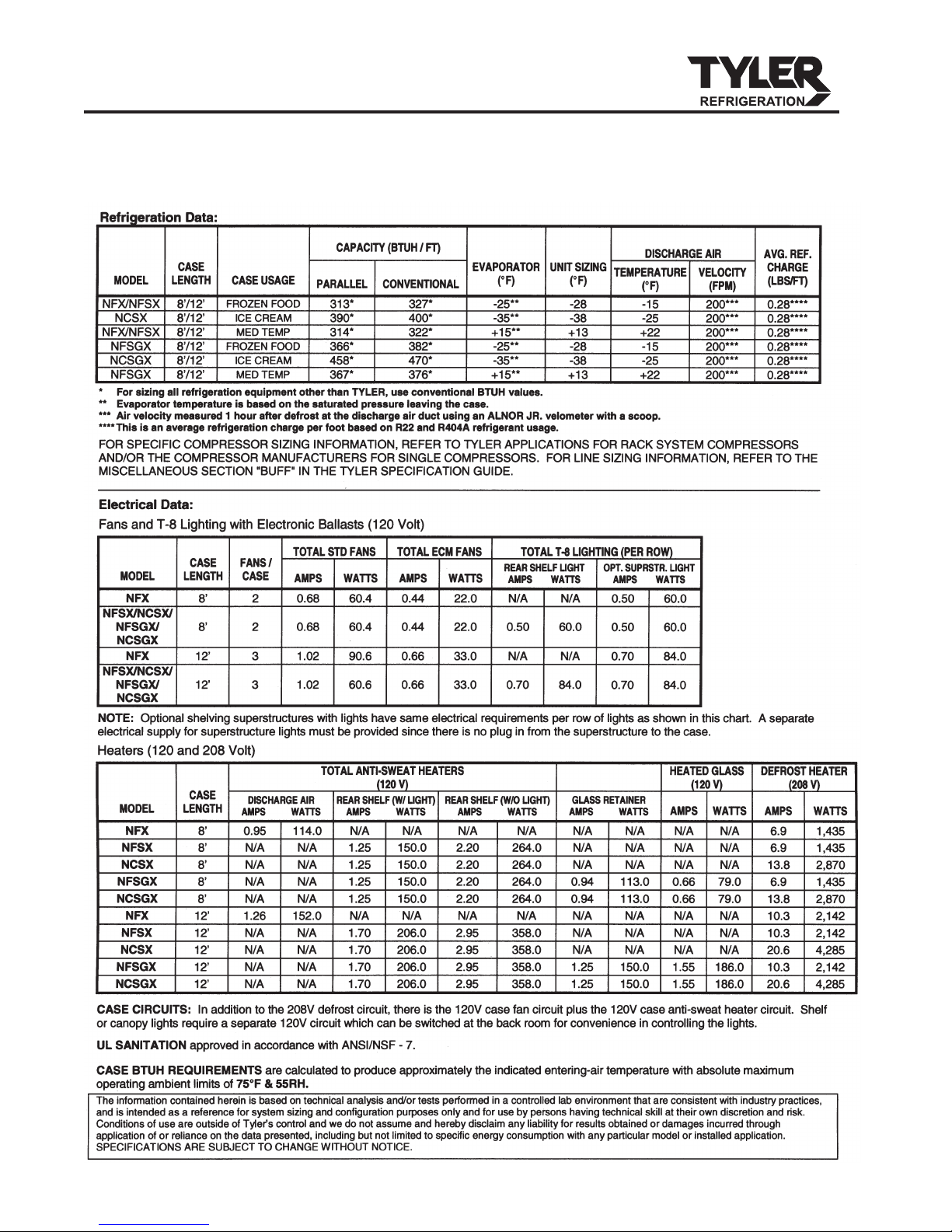
Defrost Information
See “General-UL/NSF I&S Manual” for
operational descriptions for each type of
defrost control.
Defrost Control Chart
NFX/NFS(G)X/NCS(G)X
Defrost
Defrost Defrosts Duration Term.
Type Per Day (Min) Temp.
Electric/FF 1 60 50°F
Elec/IC/MED 1 36 50°F
Gas/FF 2-3 20-25 55°F
Gas/IC 1 25-30 55°F
Gas/MED 2-3 16-20 55°F
Most klixons are located on the end of the
evaporator coil. Klixon uses are as follows:
Electric Defrost Termination, Electric Defrost
Failsafe (Opt.), Gas Defrost Fan Delay (Dual
Temp) and Glass Anti-Sweat (Dual Temp).
NOTE
The defrost termination klixon for gas
defrost is located at the bypass check
valve.
CAUTION
If electronic sensors are used in place of
the klixons, the sensors must be located
in the same location as the klixons for that
defrost type. Any other locations will effect
the refrigeration efficiency of the case.
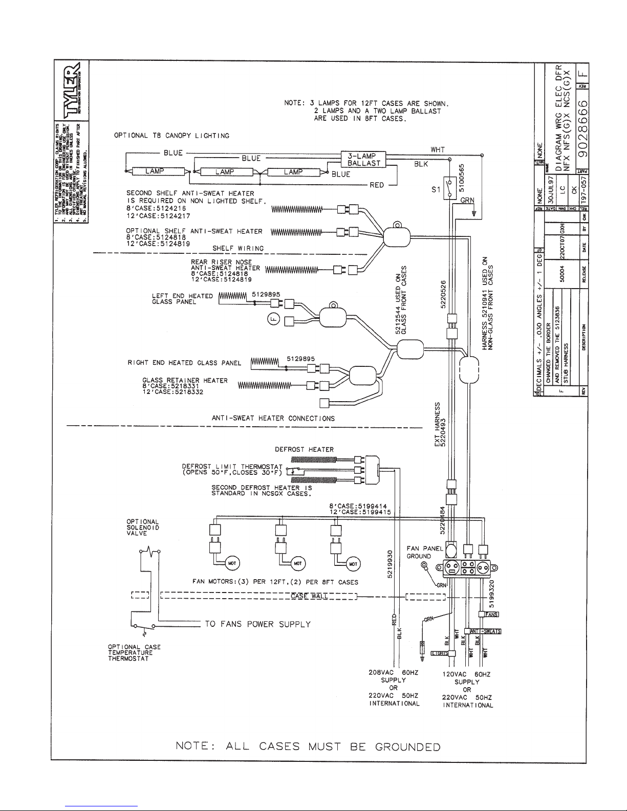
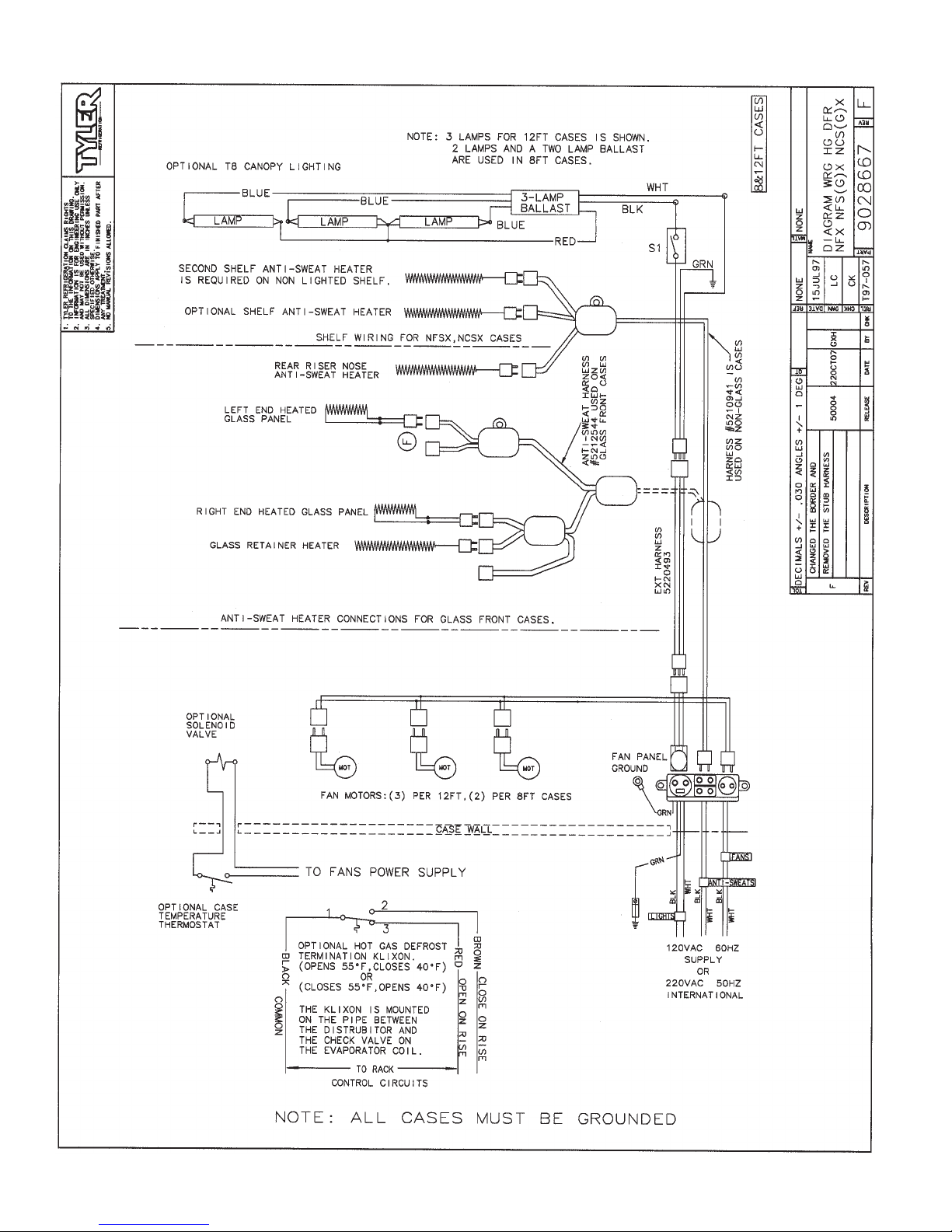
WIRING DIAGRAMS
ELECTRICIAN NOTE - OVERCURRENT
PROTECTION
120V circuits should be protected by 15 or 20 Amp
devices per the requirements noted on the cabinet
nameplate or the National Electrical Code, Canadian
Electrical Code - Part 1, Section 28. 208V defrost
circuits employ No. 12 AWG field wire leads for field
connections. On remote cases intended for end to
end line-ups, bonding for ground may rely upon the
pull-up bolts.
The following wiring diagrams on pages 9 thru
11 will cover the NFX/NFSX/NCSX/NFSGX/
NCSGX case circuits and dual temp circuits
with electric and hot gas defrost options.