Heatcraft IV Series User manual

Part No.: IM_010A
Page No.: 1of 17
EN No.: 56667
Issue: A
Date: 30/4/18
Heatcraft Subco Pty Ltd ACN 42 624 910 041
HEATCRAFT FRIDGEBOX SERIES IV HANDBOOK
For Units 2 –6 HP
THANK YOU FOR CHOOSING THE HEATCRAFT FRIDGEBOX SERIES IV CONDENSING UNIT.
TO ENSURE TROUBLE FREE INSTALLATION AND COMMISSIONING, PLEASE REFER TO THE
CONTENTS OF THIS HANDBOOK.
IMPORTANT INFORMATION -
REFER TO THE SECTIONS ON “WARNINGS AND SAFEGUARDS”, AND “INSTALLATION
INSTRUCTIONS” BEFORE ATTEMPTING TO COMMISSION THIS CONDENSING UNIT.

Heatcraft Subco Pty Ltd Document No.: IM-010A
Page No. : 2of 17
CONTENTS
End User Notes......................................................................................................................................... 3
General Notes....................................................................................................................................... 3
Auto Start-Up ....................................................................................................................................... 3
Auto Reset............................................................................................................................................ 3
Routine Maintenance of Unit ............................................................................................................. 3
Warnings and Safeguards.......................................................................................................................... 4
Important Notes.................................................................................................................................. 4
No Smoking..................................................................................................................................... 4
Warning –Electrical Hazard......................................................................................................... 4
Caution –Unit Pressurized............................................................................................................. 4
Caution –Refrigerant Type............................................................................................................ 4
Caution –Lubricant Oil Type ........................................................................................................ 4
Caution –Sharp Edges ................................................................................................................... 5
Warning –Qualified Personnel.......................................................................................................... 5
Personal Protective Equipment.......................................................................................................... 5
Caution –Lifting of Unit .................................................................................................................... 5
Caution –High and Low Temperatures ............................................................................................ 5
Caution –Deep Vacuum..................................................................................................................... 5
Caution –Motor Protection................................................................................................................ 5
Caution –Internal Pressure Relief (IPR) Valve ................................................................................ 6
Purpose.................................................................................................................................................... 6
Standard Design Conditions................................................................................................................... 7
Installation Instructions............................................................................................................................. 7
Unpacking of Unit ................................................................................................................................ 7
Installation Location ............................................................................................................................. 7
Refrigeration Piping.............................................................................................................................. 7
Electrical Connection............................................................................................................................ 8
Lubrication ........................................................................................................................................... 8
Compressor Starting.............................................................................................................................. 9
Compressor Crankcase heater ........................................................................................................... 9
Scroll Compressor Operating Sounds................................................................................................ 9
Scroll System Charging Procedure........................................................................................................ 9
Internal Pressure Relief Valves (IPR valves)..................................................................................... 9
ZB Scroll Compressor Functional Check ........................................................................................ 10
System Holding Charge ...................................................................................................................... 10
Pressure Settings................................................................................................................................. 10
General Commissioning & Decommissioning Guide .............................................................................. 12
Warning –Commissioning............................................................................................................... 12
Warning –Decommissioning.............................................................................................................. 13
Material Safety Data Sheets –M.S.D.S............................................................................................ 13
Important Notes................................................................................................................................ 13
General Arrangement Drawing ............................................................................................................. 14
WIRING SCHEMATIC DIAGRAMS.................................................................................................... 15

Heatcraft Subco Pty Ltd Document No.: IM-010A
Page No. : 3of 17
End User Notes
General Notes
Heatcraft FRIDGEBOX SERIES IV condensing units fall under the requirements for commercial
electrical equipment as per Standards Heatcraft guidelines. Installation and major service of this
unit must be carried out by a licensed contractor and in accordance with local regulatory guidelines.
Under no circumstances should anyone other than a qualified person attempt to gain
access to the interior of the unit without first ensuring electric power is disconnected.
FRIDGEBOX SERIES IV condensing units have been designed for use in an outdoor or indoor
environment. HTS condensing units are not suitable for mobile and explosion-proof applications.
Auto Start-Up
FRIDGEBOX SERIES IV condensing units may start automatically without any warning. Please
see “Installation Instructions” for further details.
Auto Reset
Kirby Fridgebox condensing unit fans and compressors are thermally protected. When tripped,
these components will not operate. Once sufficiently cooled however, the component will
automatically reset and may operate without warning.
The unit is equipped with a High/Low pressure switch as standard. The switch is either a universal
selectable auto or manual reset or fixed auto/auto-reset type on both high and low sides. If
universal switch used then it is set to auto/auto at the factory. Please check the unit regarding the
appropriate pressure switch.
Routine Maintenance of Unit
Condenser:
The Fridgebox Series IV utilises an all-aluminium microchannel condenser coil that is flexibly
mounted to the adjoining sheetmetal at the non-header end. The mounts should be periodically
checked for condition and freedom of movement.
The Condenser should be cleaned at 3 monthly intervals using low pressure water spray.
For repair of microchannel coils, please refer to your local Heatcraft representative.
System operation:
System operation should be checked every 6 months. Checks should include:
Operating conditions such as condensing and evaporating temperatures, compressor
discharge temperature, superheat and sub-cooling, etc.
Refrigerant charge, oil level and quality
Electrical connections, current draw and voltage level, etc.
Heatcraft Subco Pty Ltd Document No.: IM-010A
Page No. : 4of 17
Warnings and Safeguards
Heatcraft is very conscious of safety issues when designing and manufacturing these products, but it is
essential that the end user, installer or service personnel also exercises care when working with the units.
Important Notes
Do NOT remove access panels without isolating power.
Do NOT operate unit with access panels removed due to the presence
of rotating equipment.
Do NOT operate unit with access panels removed as there will be no
air flow over the condenser.
All controls are 230/240V.
No Smoking
Heatcraft recommends No Smoking within a distance of 15 metres of the unit.
Warning –Electrical Hazard
A qualified Electrician must carry out all electrical work. All field wiring must conform to the
requirements of the equipment and all applicable National and Local Codes.
Always isolate the power to the unit before checking and / or diagnosing the units. Never work on
any electrical item without isolating or disconnecting the power supply.
Caution –Unit Pressurized
All units are pressurised with dry air or Nitrogen gas. Care must be taken to discharge the
pressurized gas prior to installing or commissioning the equipment.
Caution –Refrigerant Type
All units are designed to work effectively with fluorocarbon refrigerants including R404A and
R134a. Under no circumstances can a refrigerant such as R410A, Ammonia, Hydrocarbon, Water
or Glycol be used in this product.
Refrigerant can be harmful if it is inhaled and/or makes contact with exposed skin.
Refrigerant must be used and recovered responsibly. Extreme care must be taken when
handling refrigerant, as personnel injury or death may occur.
Caution –Lubricant Oil Type
All compressors are charged with PolyolEster (POE) oil. POE can be used with HCFC refrigerants,
such as R22, and HFC refrigerants, such as R404A, R507, R407C and R134a. Use ONLY POE oil,
do NOT mix POE with other oils, when using HFC refrigerants.
Caution –Sharp Edges
Warning
This indicates contents for which, if disregarded, the possibility of human death or
severe injury can be assumed.
Caution
This indicates contents for which, if disregarded, the possibility of human injury or
the possibility of material damage can be assumed.

Heatcraft Subco Pty Ltd Document No.: IM-010A
Page No. : 5of 17
All units are manufactured with sheet metal and in this process all care is taken to ensure the edges
are concealed. Avoid contact with sheet-metal edges and the coil fins. They can be sharp and are a
potential personal injury hazard. Please take care when accessing in or around the unit.
Warning –Qualified Personnel
All units may only be installed, commissioned, decommissioned and serviced by qualified and
trained personnel (refrigeration mechanics and/or electricians) who have sufficient knowledge in
this type of equipment. It is the purchaser’s responsibility to co-ordinate with qualified personnel
as required.
Personal Protective Equipment
Heatcraft recommends as a secondary safety precaution that all personnel working with the unit
wear appropriate Personal Protective Equipment (PPE) such as gloves, eyewear and footwear.
Caution –Lifting of Unit
The compressor end of the unit is to the left looking from the front (fan discharge) side. Forks
should be placed toward the left hand mounting foot when lifting. Slings can be placed through
the mounting feet but care must be taken to adjust the lengths appropriately to account for the
weight distribution.
UNIT APPROX.WEIGHT
MODEL UNPACKED PACKED
FBH043MHZ1-2 84 99
FBH051MHZ1-2 86 101
FBH066MHZ1-2 83 103
FBH075MHZ1-2 84 104
FBH086MHZ1-2 93 113
FBH103MHZ1-2 94 114
FBH116MHZ1-2 96 116
kg
Always take care to ensure a proper weight balance before lifting and moving unit.
Caution –High and Low Temperatures
Compressor housing and discharge line temperatures may reach 150°C due to failure of system
components. Wiring and other materials which could be damaged by these temperatures should not
come into contact with the housing or discharge line.
Moreover, even in normal working operation, the unit can generate very high (may exceed 100°C)
and very low (below -40°C) temperatures on compressor housing and tubing surfaces resulting in
the possibilities of severe contact burns. Special caution must be taken when working around the
unit.
Caution –Deep Vacuum
Do NOT operate compressors in deep vacuum conditions as this can cause electrical failure.
Compressors should never be used to evacuate refrigeration or air conditioning systems.
Caution –Motor Protection
WARNING: Do not insert any object into operating fans. Ignoring this warning may result
in personal injury and/or severe equipment damage and consequences.

Heatcraft Subco Pty Ltd Document No.: IM-010A
Page No. : 6of 17
Copeland ZB/ZF hermetic scroll compressors, and the fan motors fitted to these units, are fitted
with inbuilt motor protection. The protection may be internal line break, or externally connected
control break type. After opening, the protector may not reset for several hours until the motor
cools sufficiently. Do not assume that the motor has suffered an open circuit failure without first
allowing it to cool.
Scroll compressors can only run in one direction. Refer to Installation and Commissioning
Instructions for details of how to identify if the compressor is running correctly.
In addition to the above, thermal over-current protection is fitted to the compressor contactor(s),
and MP15 phase failure protection is provided as a standard configuration.
The MP15 start delay function has been utilised as follows-
HP/LP alarm to pin 5- delay with memory function and light
Compressor contactor K1 Thermal Overload N/O 97-98 to pin 8 (start delay without
memory or light).
Compressor restart will be delayed by 15 minutes when activated by these 2 fault conditions.
Restarting the MP15 (toggle Circuit Breaker CB1 Off/On) will re-initialize the MP15 timer.
Please refer to your Heatcraft sales representative for details.
Caution –Internal Pressure Relief (IPR) Valve
ZB/ZF scroll compressors include an IPR valve. The IPR valve will open when the discharge
pressure exceeds the suction pressure by a certain value, which is set by the compressor
manufacturer. When it has opened, the compressor sump will become warm and the compressor
will trip out on the motor protector. The unit may take 2 to 3 hours to reset and restart
automatically if this happens.
Do NOT assume that a compressor that is running, but not pumping, is faulty.
Stop the compressor and allow the pressures to balance, and then start the compressor again.
Caution –ASTP compressor temperature protection
ZB scroll compressors may be equipped with an ASTP device which is designed to prevent
overheating of the scroll components, by opening a valve which bypasses discharge gas to the
suction side and heating the compressor thermal protection device which switches the compressor
off. This may take some time and the compressor will appear to not be pumping, and making a
hissing noise. The compressor will restart once the thermal protection device cools sufficiently.
The fitment of the device will be noted on the compressor itself.
Purpose
FRIDGEBOX SERIES IV condensing units are standard OEM products of Heatcraft including
high, medium (ZB) and low (ZF) temperature application ranges. They are designed for
continuously supplying and receiving the refrigerant to and from the evaporator(s), and rejecting
the heat extracted from the cold space to the surrounding atmosphere where the units are installed.
FRIDGEBOX SERIES IV condensing units are intended for installing in a typical ventilated
indoor or outdoor environment (Refer to the General Arrangement Drawing section for details)
with the condensing temperature no greater than 60°C and compressor return vapour temperature
no greater than 20°C.
Heatcraft Subco Pty Ltd Document No.: IM-010A
Page No. : 7of 17
They are not intended for environments that may have harmful, corrosive or flammable
atmospheres. Marine environments are considered corrosive; please consult Heatcraft before
installing in this environment.
Standard Design Conditions
MAXIMUM ALLOWABLE PRESSURES (PS, PSS)
Maximum allowable pressure (PS, PSS) is based on the design pressure or maximum allowable
pressure of the lowest rated component in the system.
MAXIMUM AMBIENT
Maximum ambient condition is based on calculated maximum condensing pressure for various
permitted refrigerants. Calculations have been verified by testing sample units of each unit range
UNIT DATA
PS PSS Refrig
FRIDGEBOX kPAg kPag
43°C 2880 2100
A1:
R404A/
R134a
AS/NZS5149.2 INFORMATION.
MAX AMB
STD- ZB COMPRESSORS
Medium temperature range condensing units are typically designed, for primary refrigerant
R404A, to be used in commercial cool room applications ranging from -15°C to +10°C saturated
suction temperature for ZB compressors. R404A and R22 are recommended refrigerants.
For R134a usage, please refer to other sections of this booklet for control setting information etc.
For special design requirements (non standard conditions and/or refrigerants), please inquire with your local
representatives and/or Heatcraft local branches, or call our national telephone number 13 23 50 for your
nearest available information resources.
Installation Instructions
Unpacking of Unit
When unpacking, check for any damage to packing material or the unit itself which may affect the
unit’s performance. If any such damage is evident, please contact your local Heatcraft branch.
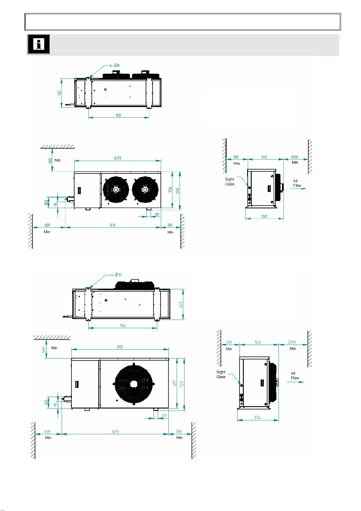
Installation Location (Refer to the General Arrangement Drawing section)
If the unit is to be located in close proximity to a wall or similar obstruction, the minimum distance
from the coil face to the obstruction shall comply with the general arrangement drawing. The unit
shall be mounted on a horizontal plane surface.
The liquid sight glass is located inside the left hand side compartment (looking from the front).
Allow sufficient space around the access panels for opening the panels.
Connection of gauges can be achieved from the compressor compartment of the unit, refer to the
section on pressure settings for more detail.
It is particularly important for the units to allow sufficient unobstructed air-discharge space
in front of the unit to prevent warm air recirculation to the condenser.
Refrigeration Piping
Heatcraft Subco Pty Ltd Document No.: IM-010A
Page No. : 8of 17
Refrigeration piping work shall be carried out professionally by qualified refrigeration
mechanics in accordance with applicable national and local regulations and in conformance
with good engineering practices required for the proper operation of the refrigeration
system.
All FRIDGEBOX SERIES IV condensing units manufactured by Heatcraft are supplied clean and
internally charged with dry air or nitrogen to prevent oxidation and ingress of moisture or foreign
matter. Care shall be taken during installation of the piping to prevent entrance of foreign matter or
moisture by minimising the time that the piping is uncapped.
The interconnecting refrigeration pipe size is not necessarily the same size as the outlet on the unit.
The pipe sizes shall be selected / calculated based on the best compromise of minimizing
refrigerant pressure drop and refrigerant velocity to ensure efficient oil return. Heatcraft can
provide a software program to assist in the calculation of pipe sizes.
Horizontal suction lines shall slope towards to the units to allow the oil return freely to the
compressor by gravity. A 1:100 slope is considered sufficient. The use of oil trap and double risers
may be necessary on vertical sections. Suction line piping shall be insulated to minimise the
superheat effect to the vapour.
If in doubt during the installation, please consult with your local sales representatives and/or
application engineers from Heatcraft for technical support.
Electrical Connection All electrical connections must be carried out by a licensed
electrical contractor and in accordance with the relevant
regulations.
Both the mains supply and the control cabling must be brought into the electrical section from the
side of the unit. The cables should be passed though the glands provided before being run to the
terminals (Refer to Wiring Schematic inside electrical box cover). Refer to the name plate for all
the information regarding voltage and current for the unit.
Mains supply cabling must be in accordance with relevant standards and / or codes, Control circuit
is 240 volts. Terminals are supplied for connection of control circuit (Refer to Wiring Schematic
inside electrical box cover).
Warning –Electrical Hazard
Only qualified personnel should attempt to bypass the interlock. Caution must be exercised
when working on the unit if the interlock is bypassed.
Lubrication
FRIDGEBOX SERIES IV Copeland Hermetic ZB Scroll compressors use polyolester oil. In the
field if the original manufacturers specification oil is not available, the oil level could be topped up
with ICI Emkarate RL 32. The oil charge must be checked before commissioning (see below).
Check the oil level again after a minimum of 10min operation at nominal conditions. This
operation should be repeated at least twice to make sure the proper oil level has been achieved.
OIL LEVELS:
Copeland ZB & ZF Scroll Compressors: The oil level should be maintained at 1/2 of the oil
sight glass.
Caution - Notes on POE Oils

Heatcraft Subco Pty Ltd Document No.: IM-010A
Page No. : 9of 17
Use only POE oil with HFC refrigerants. Do NOT mix POE oil with other oils when using
HFC refrigerants (eg R404A).
Compressor Starting
DOL START
All compressors are 380-420V 3Ph 50Hz STAR connected motors for Direct-On-Line starting.
Care should be taken to establish starting requirements for the larger compressors due to high in-
rush current.
Maximum compressor starts per hour
Scroll compressors = 10
Compressor Crankcase heater
The crankcase heater is mounted below the oil removal valve located on the bottom shell. The
crankcase heater remains energised during compressor off cycles.
Scroll Compressor Operating Sounds
Start Up - Normal
During the very brief start-up, a short metallic sound may be audible.
Start Up - Incorrect Wiring
Because scroll compressors are directionally dependant, 3 phase compressors must be wired to
rotate in the correct direction. Correct rotation can be verified by observing that a drop in suction
pressure and a rise in discharge pressure occurs. Also, reverse rotation results in a sound level
higher than that produced when rotation is correct.
Note that no damage will be caused by operating scroll compressors in the reverse direction, and
after several minutes of operation, the compressor’s internal protector will trip.
The rotation direction can be reversed by swapping any two of the phase connections.
Shut Off
During shut off, a brief audible sound may occur.
Scroll System Charging Procedure
Avoid rapid charging from the suction side as this can cause a temporary no-start condition due to
scroll component characteristics. The best method for initial charging is to simultaneously charge
from both high and low sides (Please refer to Commissioning Section for more details).
Should a scroll compressor fail to start and the above condition is suspected, reverse any two of the
3 phase leads and momentarily power the compressor (1-2 seconds) in the reverse direction.
Internal Pressure Relief Valves (IPR valves)
All FRIDGEBOX SERIES IV compressors are fitted with IPR valves with a discharge to suction
differential of 26~31bar.
ASTP temperature protection.
ZB scoll compressros may be fitted with ASTP over-temperature protection. The compressor may
run for a short period of time but will not pump refrigerant once the protector has been triggered.
The compressor will stop on the motor thermal overload device. The fitment of the device will be
noted on the compressor itself.

Heatcraft Subco Pty Ltd Document No.: IM-010A
Page No. : 10 of 17
Scroll Compressor Functional Check
Since scroll compressors do not have internal dynamic suction or discharge valves, it is not
necessary to perform valve plate efficiency tests, ie running the compressor with the suction
service valve closed. This type of test may damage a scroll compressor.
System Holding Charge
The system as supplied is pressurised at the factory with Dry Air or Nitrogen gas.
If the system is not pressurised on delivery, please contact your Heatcraft branch. Care must
be taken to release the pressure before attempting to gain access to any part of the
refrigeration system.
The unit should be evacuated to a pressure of 500 microns (mHg) prior to commissioning.
Pressure Settings
PRESSURE RELIEF VALVES (Where required)
High Side- Pressure relief valves must be selected based on the system PS. The maximum
allowable pressure of the pressure vessel may not determine the PRV setting if it is not the
lowest rated system component. Please note the condensing unit may NOT be the lowest
rated component in the system.
Low Side (where applicable)- Pressure relief valves must be selected based on system PSS.
Please note that the low side of the condensing unit may NOT be lowest rated component in
the system.
HP CONTROL SETTING
Compressor HP (where fitted)- Setpoint must be equal to or less than 90% of the compressor
PS.
Unit HP- Setpoint must be equal to or less than 90% of the PRV setting (where fitted), or less
than or equal to Unit PS if no PRV fitted.
Please note this setting may not be adequate to protect other parts of the system with a lower
PS rating. If required the Unit HP may be set to less than or equal to the sysetm HP.
Note when setting the HP control- Consideration must also be given to the type of refrigerant
used and the maximum ambient temperature to ensure compliance with AS/NZS5149.2 and
avoiding nuisance tripping.
Heatcraft also recommends the LP switch to be used as a safety protection device. Depending on
the application and compressor, LP cut-in and differential points should be set with the following
considerations:
Set the cut-out points at 3–5 K below the respective minimum design saturated suction
temperatures (Refer to the Standard Design Conditions section for saturated suction
temperature ranges).
Set the differential to no more than 2 Bar.
The cut-out pressure shall be in the positive pressure region.
When the unit is installed in a cold ambient, the cut-out pressure shall be lower than the
pressure corresponding to the ambient temperature.
Access points for gauges are located on post valves in the compressor compartment. They
can be accessed from the compressor compartment access panel.
Fan Speed Control
A fan speed controller is fitted as a standard item to all Fridgebox condensing units from 2 –7 hp.
The factory setting is suitable for R404A on medium temperature applications. For other
applications and other refrigerants, please refer to the setting instructions below.
Units are installed with direct mount pressure actuated condenser fan speed controller as follows.

Heatcraft Subco Pty Ltd Document No.: IM-010A
Page No. : 11 of 17
“XGE-4CC30” from SAGINOMIYA SEISAKUSHO
This controller varies the supply voltage to the condenser fan motor from 30% to at least 95% over
the proportional condensing pressure band which is factory fixed at 6 Bar.
The set point is defined at 90% supply voltage to the fan motor, and is set at 19 Bar by the control
manufacturer. By turning the setting screw clockwise, the pressure setting increases. Turn anti-
clockwise to decrease the pressure setting. It is approximately 1.5 Bar per full (360°) turn.
The cut-off point is defined at 30% supply voltage to the fan motor, and corresponds to 13 Bar
depending on actual load and / or power supply.
When the condensing pressure reduces to the cut-off condition, the controller will cut off the
supply to the fan and the fan will stop. The fan restarts at low speed when the pressure rises. For
details, please refer to Saginomiya product specification.
Heatcraft factory set point for primary refrigerant R404AR407F is 19 Bar(g) for M/T and 14 Bar(g)
for L/T units. Heatcraft recommends 10 Bar(g) for R134a units.
Repair of the controller is not possible. In case of an improperly functioning control, please check
with your nearest Heatcraft Refrigeration Branch.
Warning –Setting for Other Refrigerants
It is the installer’s responsibility to set the control correctly for use with refrigerants other
than R404A.

Heatcraft Subco Pty Ltd Document No.: IM-010A
Page No. : 12 of 17
General Commissioning & Decommissioning Guide
Warning –Commissioning
Refrigeration system commissioning shall be carried out professionally by qualified
refrigeration mechanics in conformance with good engineering practices required for the
proper operation of the refrigeration system.
After all installation and electrical work is completed, the entire refrigeration system must be leak
tested. After satisfactory testing of the refrigeration system, then refrigeration lines shall be
insulated as necessary. The insulation located in outdoor environments shall be protected from UV
exposure.
Before charging the refrigerant, the entire refrigeration system shall be evacuated by connecting a
good, high vacuum pump to both the high-pressure side and low-pressure side service valves or
ports.
It is important to apply good engineering practice when charging any refrigerant, but in particular
blended (zeotropic) refrigerant, such as R404A, require proper procedures to be observed:
Initially charge 60 to 80% of the expected refrigerant charge in liquid form into the liquid
receiver with the compressor not running (after evacuation to the correct pressure).
When the system pressure has stabilized, start the compressor & slowly charge the
remaining refrigerant quantity into the suction line in liquid form through a gauge manifold
or a throttling valve to allow it to vaporize before entering the compressor. If the system is
fitted with an accumulator, it is preferable to charge upstream of the accumulator.
After initial running of the system, check the refrigerant charge condition at the sightglass
and add any required refrigerant in the suction side as noted above, or remove excess
refrigerant into an approved reclaim cylinder.
Heatcraft is dedicated to providing safe products and protecting the environment by complying with all
applicable national laws and regulations governing environmental protection. New and used refrigerants
cannot be vented into atmosphere. Reclaim all used refrigerants. Ensure your refrigerant handling procedure
complies with the relevant regulations.
Double check all field wiring connections and factory terminations. Factory connections can
vibrate loose during shipment. Ensure correct fan motor rotation, airflow is induced from coil side
and forced out of fan motor side.
If fitted, ensure that the crankcase heater has been energised for a minimum 12 hours before initial
start-up and / or after prolonged shutdown periods.
After the successful start up of the system, check:
Current draw and voltage levels.
Suction superheat settings and discharge temperatures.
Abnormal refrigeration piping vibrations.
Oil level and refrigerant charge.

Heatcraft Subco Pty Ltd Document No.: IM-010A
Page No. : 13 of 17
Warning –Decommissioning
In order to remove the unit from its mounting place, the following procedures need to be
carried out professionally by qualified personnel. Failure to do so may result in personal
injury or death, property damage by fire or explosion. Discharge of refrigerant to
atmosphere is illegal and may result in heavy fines by relevant regulatory authorities.
Pump down the entire refrigerant charge into the liquid receiver or appropriate container such
as reclaim cylinder, and shut related valves. All reclaimed refrigerant that is not re-used
must be taken to an approved refrigerant recycling or destruction facility.Heatcraft
Branches will accept the used refrigerant.
Disconnect the power supply. Remove all necessary field electrical wiring and related
components, leaving the earth wire to the last.
Care must be taken when disconnecting the refrigeration piping because of unbalanced
pressure between the unit and ambient. There may be a small amount of refrigerant trapped in
the oil, the pressure rise in the system will boil and vaporise the refrigerant resulting in a
potential personal injury hazard.
Cut and solder seal the refrigeration liquid line and suction line pipe connections.
Remove the unit from its mounting place. Adequate equipment must be provided as per lifting
notes.
Material Safety Data Sheets –M.S.D.S.
These are available from your nearest Heatcraft Branch for all refrigerants that Kirby Titan
condensing units are approved for, and for oils and other materials as needed.
Important Notes
To ensure FRIDGEBOX SERIES IV condensing units operate efficiently and for a long working
life, always obtain genuine replacement parts from your local Heatcraft Wholesale Branch.
Genuine replacement parts are covered by the warranty. Refer to the Standard Terms & Conditions
of Sale in the Price Guide for warranty statements.
Continuous product improvement is our company policy. Heatcraft reserves the right to make
changes in product specifications and/or this instruction manual without notice.
Heatcraft is dedicated to providing safe products and protecting the environment by complying with all
applicable national laws and regulations governing environmental protection. New and used refrigerants
cannot be vented into atmosphere. Reclaim all used refrigerants. EPA regulations are constantly updated.
Ensure your refrigerant handling procedure complies with the relevant regulations.
Heatcraft Subco Pty Ltd Document No.: IM-010A
Page No. : 14 of 17
General Arrangement Drawing
-------------------------------------------------------------------------------------------------------------------------
Heatcraft Subco Pty Ltd Document No.: IM-010A
Page No. : 15 of 17
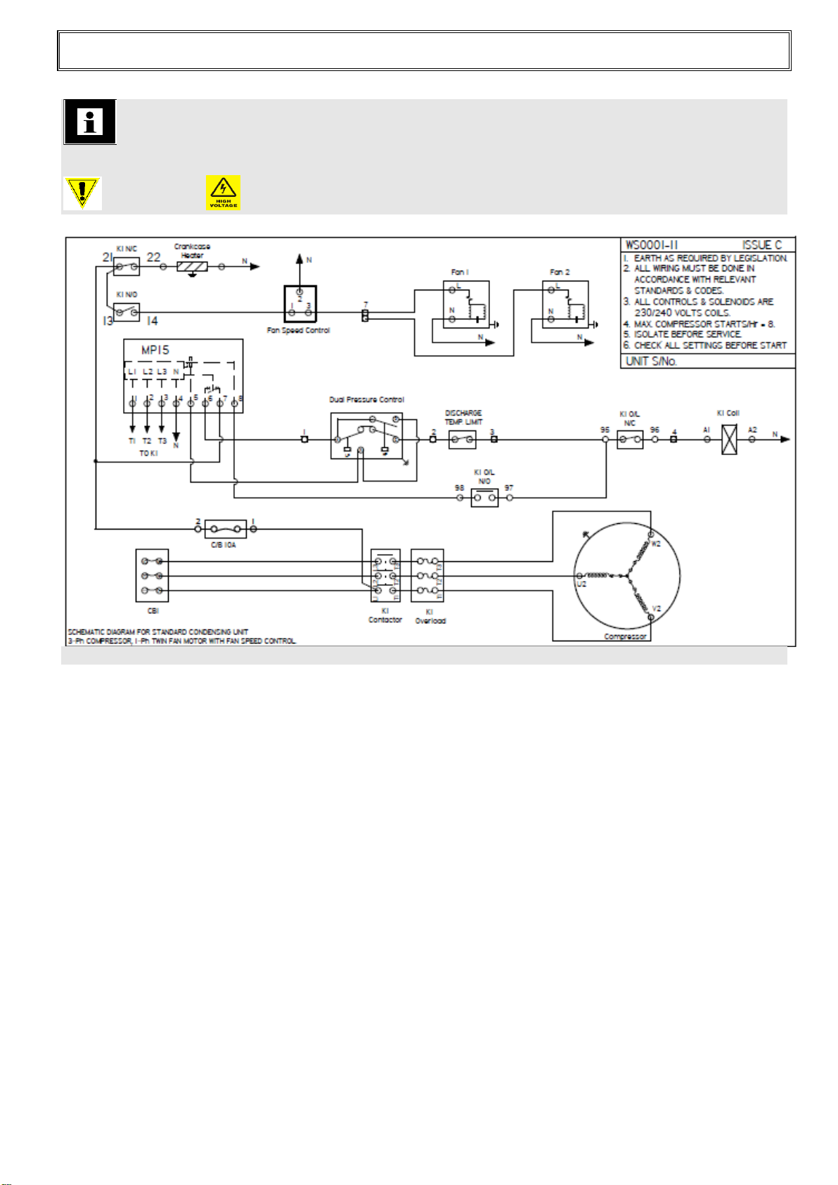
WIRING SCHEMATIC DIAGRAMS
FRIDGEBOX SERIES IV 2x 350mm Fan
Warning Electrical 380 / 420 Volt
Heatcraft Subco Pty Ltd Document No.: IM-010A
Page No. : 16 of 17
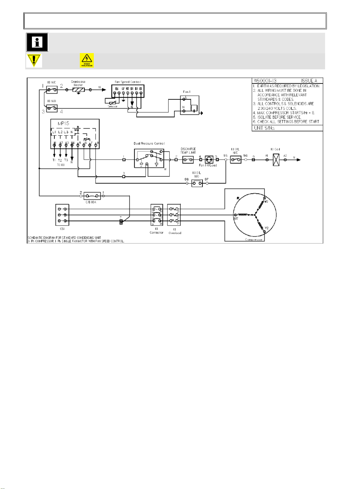
FRIDGEBOX SERIES IV 1x 500mm Fan
Warning Electrical 380 / 420 Volt

Heatcraft Subco Pty Ltd Document No.: IM-010A
Page No. : 17 of 17
INSTALLATION NOTES
286 HORSLEY ROAD MILPERRA NSW 2214
LOCKED BAG 63 WETHERILL PARK NSW 1851
A.B.N. 42 624 910 041
HEATCRAFT SUBCO PTY LTD
This manual suits for next models
7
Table of contents
Other Heatcraft Freezer manuals


