Heatrae Sadia Handy 3 NT User manual

Handy No Touch Electric Handwash
Fitting Instructions
Important
Please read & understand all these instructions
before commencing installation.
Please leave this manual with the customer for future
reference

This product can be used by children aged from 8 years and above and
persons with reduced physical sensory or mental capabilities or lack
of experience and knowledge if they have been given supervision or
instruction concerning use of the product in a safe way and understand
the hazards involved. Children shall not play with the product.
Cleaning and user maintenance shall not be made by children without
supervision. Children must be supervised to ensure they do not play
with the product.
Contents
1. Introduction...............................................................................................3
1.1 General ...............................................................................................3
1.2 Symbols used......................................................................................3
1.3 Abbreviations.......................................................................................3
1.4 Liabilities .............................................................................................3
2. Safety.........................................................................................................4
2.1 General safety warnings .....................................................................4
2.2 Recommendations ..............................................................................4
2.3 Specic safety instructions..................................................................4
3. Technical specications ..........................................................................5
3.1 Technical data .....................................................................................5
3.2 Dimensions and connections ..............................................................5
3.3 Electrical diagram(s) ...........................................................................6
4. Description of the product.......................................................................7
4.1 General description .............................................................................7
4.2 Operation principle ..............................................................................7
4.3 Standard delivery ................................................................................7
4.4 Main components................................................................................7
5. Before installation ...................................................................................8
5.1 Installation regulations ........................................................................8
5.2 Installation requirements .....................................................................8
5.3 Choice of location................................................................................9
6. Fitting Instructions ...................................................................................10
6.1 General ...............................................................................................10
6.2 Water connections...............................................................................10
6.3 Electrical connections .........................................................................11
7. Commissioning.........................................................................................12
7.1 General ...............................................................................................12
7.2 Checklist before commissioning..........................................................12
7.3 Commissioning procedure ..................................................................12
8. Operation...................................................................................................12
8.1 General ...............................................................................................12
9. Maintenance..............................................................................................13
9.1 General ...............................................................................................13
10. Troubleshooting.....................................................................................14
10.1 Decommissioning procedure.............................................................14
11. Spare parts .............................................................................................15
Warranty ........................................................................................................15
3
1. Introduction
1.1 General
The following instructions are offered as a guide to
the user and installer.
The installation must be carried out by a competent
plumbing and electrical installer in accordance
with Building Regulation G3 (England and Wales),
Technical Standard P3 (Scotland) or Building
Regulation P5 (Northern Ireland) and the Water
Fitting Regulations (England and Wales) or Water
Byelaws (Scotland).
1.2 Symbols used
In these instructions, various risk levels are employed
to draw the user’s attention to particular information.
In doing so we wish to safeguard the user, avoid
hazards and guarantee the correct operation of the
product.
WARNING
Risk of dangerous situation causing slight
physical injury.
CAUTION
Risk of material damage.
Signals important information.
1.3 Abbreviations
`PRD – Pressure relief device
`RCD – Residual current device
`MCB – Miniature circuit breaker
1.4 Liabilities
Manufacturers liability
Our products are manufactured in compliance with
the requirements of the various applicable European
Directives.
This product complies with the requirements of the
CE marking directive.
In the interest of UK customers, we are continuously
endeavouring to make improvements in product
quality. All the specications stated in this document
are therefore subject to change without notice.
Our liability as the manufacturer may not be invoked
in the following cases:
`Failure to abide by the instructions on using the
product.
`Faulty or insufcient maintenance of the
product.
`Failure to abide by the instructions on installing
the product.
Installer's liability
The installer is responsible for the installation and
the commissioning of the product. The installer must
respect the following instructions:
`Read and follow the instructions given in the
manuals provided with the product.
`Carry out installation in compliance with the
prevailing legislation and standards.
`Perform the initial start up and carry out any
checks necessary.
`Complete the commissioning checklist.
`Explain the installation to the user.
`If maintenance is necessary, warn the user of
the obligation to check the product and maintain
it in good working order.
`Give the instruction manual to the user.
Users liability
To guarantee optimum operation of the product, the
user must respect the following instructions:
`Read and follow the instructions given in the
manuals provided with the product.
`Call on qualied professionals to carry out
installation and initial start-up.
`Get your installer to explain your installation to you.
`Have your required checks and services done.
`Keep the instruction manuals in good condition
and close to the product.

4
2.2 Recommendations
WARNING
The plumbing installation must comply
with Water Regulations.
The supply pipe must be ushed to clear
debris before connecting to the product.
DO NOT solder pipes or ttings within
300mm once the pipework is located
in the product, as heat transfer can
damage components.
DO NOT t any form of outlet ow control
as the outlet acts as a vent for the heater
can.
DO NOT use excessive force when tting
the spout xing nut, nger tightness is
sufcient.
All plumbing connections must be
completed and checked for leaks before
making the electrical connections.
2.3 Specic safety instructions
WARNING
Before tting the product, ensure that
the consumer unit and any switches
are suitable for the additional load. If in
doubt contact your electricity supplier or
a qualied electrician.
The installation must comply with
BS 7671 ‘Requirements for electrical
installations’ (IEE Wiring Regulations).
2. Safety
2.1 General safety warnings
WARNING
ISOLATE the electrical and water
supplies before removing the cover.
ISOLATE the electrical and water
supplies BEFORE proceeding with
installation or servicing.
DO NOT operate the product if:
`It is frozen or suspected of being
frozen. See fault nding table on
page 14.
`Water ceases to ow during use.
`Water has entered inside the
product because of an incorrectly
tted cover.
`The product is damaged.
CAUTION
`DO NOT tile up to the product
after xing to the wall.
`The sprayplate must be cleaned
when any of its holes become
blocked, otherwise restriction to
the ow from the outlet spout will
result in higher temperatures and
could also cause the pressure
relief device in the appliance to
operate - see 9.1 p13.
`The product is NOT SUITABLE
for mounting into steam rooms or
steam cubicles.

5
3. Technical specications
3.1 Technical data
Model numbers
3.1kW - Handwash - 95 020 115
3.2 Dimensions and connections
151
74
235
19.5
Dimensions in mm
196.5
Inlet water
connection
Terminal
block
29
86
Cable
clamp Rear entry access
area for electricity and
inlet water supply
Supplier’s name or trade mark Heatrae Sadia
Supplier’s model identier Handy 3 NT
The declared load prole XXS
The water heating energy efciency class of the model A
The water heating energy efciency in % 38.6
The annual electricity consumption in kWh 478
Daily fuel consumption in kWh 2.200
Specic precautions that shall be taken when the water heater is assembled, installed or
maintained and disposed of at end of life
See Section 3
to 11
Figure 1
Table: Technical parameters in accordance with European Commision regulations 814/2013
and 812/2013
6
Nominal Power Rating
Model 240V 230V Minimum
cable size
3.1kW 3.1kW
12.9 amp
2.9kW
12.4 amp
1.5mm2
Materials
Backplate and cover assembly - ABS
Element(s) - Copper sheathed rod type.
Dimensions
Height - 235mm
Width - 151mm
Depth - 85mm
Standards and approvals
Complies with the requirement of EN 60335-2-35.
Complies with European Community Directives
(CE). kiwa approved.
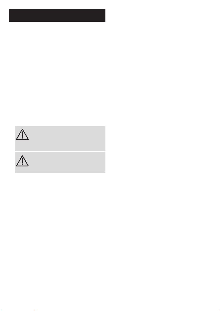
3.3 Electrical diagram(s)
Red or brown to 'L'
Green & yellow to
Blue or black to 'N'
Cable clamp
Figure 2 – Electrical connection
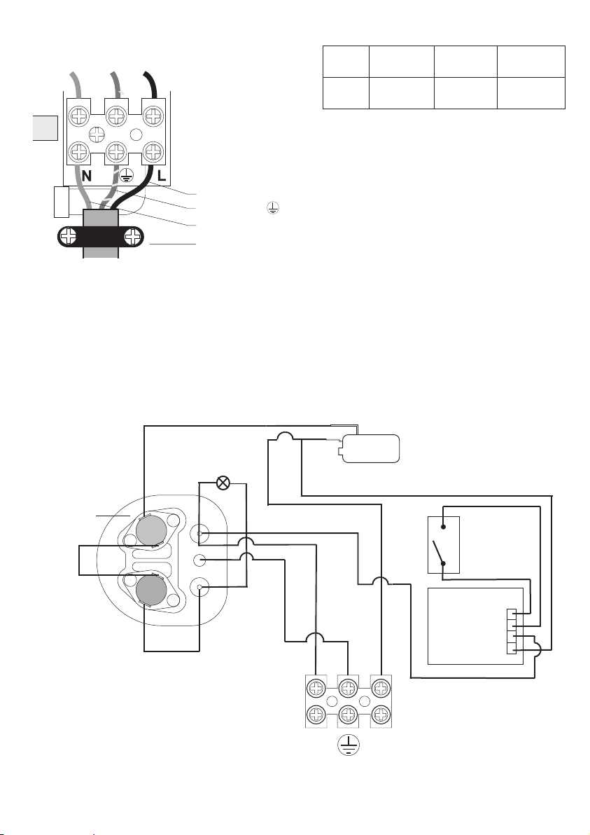
Figure 3 – Wiring diagram
Neon
Inner
container
Red
Red
Red
Cut
Out
Terminal
block
N L
Red
Red
Red
Pressure
switch
3.1kW
Black
Black
Black
Black
Green/Yellow
Solenoid
valve
PCB Infra-red
L
L
N
N
{
{
Solenoid
PCB

7
4.2 Operation principle
The product is used to provide the user with hot
water for hand washing.
By activating the sensor the water ows through the
product which then switches the element on to heat
the water.
4.3 Standard delivery
Pack contents
`Heater
`Spout assembly
`Fixing screws and plugs
`Installation and user Instructions
4.4 Main components
See Figure 4
4. Description of the product
4.1 General description
This product is manufactured to British and
European Standard. These products are safe and
without risk provided they are installed, used and
maintained in good working order in accordance with
our instructions and recommendations.
Please read and understand these instructions
before starting work and retain them for later use.
This product is a purpose designed handwash
heater. The unit has a cooper sheath element
contained in a high grade plastic canister, this with
the ow control valve is assembled into high quality
ABS plastic backplate and front cover.
Sprayplate
Oultlet spout
Spout fixing nut
Pressure relief device (PRD)
Cable clamp
Terminal block
Flow control valve
Pressure switch
Inner
container
Front
cover
Thermal
cut-out
Thermostat
Rating label
Solenoid valve
Figure 4 – Internal components
8
If the product is operated outside of the stated
pressure parameters it may not be possible to
achieve optimum performance from the product
throughout the year.
WARNING
`The product must be earthed
`IMPORTANT - INSTALLATION
TO BE CARRIED OUT BY A
COMPETENT INSTALLER
Electrical requirements
The installation supply cable and circuit protection
must conform to BS 7671.
Before making any sort of electrical connection,
ensure that no terminal within the circuit is live. If in
any doubt SWITCH OFF the whole installation at the
consumer unit.
The product must only be connected to a 230-240V
ac supply.
The earthing and protective conductor arrangement
within the property, in particular the supplementary
bonding in the room containing the product, must
comply with BS 7671.
Ensure that the supply cable and fuse are sufcient
for the rated input of your unit. Please refer to the
rating label within the product.
A minimum heat resistance cable size of 1.5mm²
should be used.
The product can be connected in two different ways:
`Via a fused and switched connection unit taken
as a spur from a 13amp ring main.
`As a separate circuit taken directly from a spare
way in a consumer unit.
In each case a double pole isolating switch having a
contact separation of at least 3mm in each pole, and
a minimum rating of 13amp must be incorporated in
the wiring of the appliance.
5. Before installation
5.1 Installation regulations
WARNING
Installation of the product must be
carried out by a qualied engineer in
accordance with prevailing and national
regulations as listed below.
`Building Regulations
`The Building Standards
(Scotland)
`The Building Regulations
(Northern Ireland)
`I.E.E Electrical Regs
`UK Water Regulations
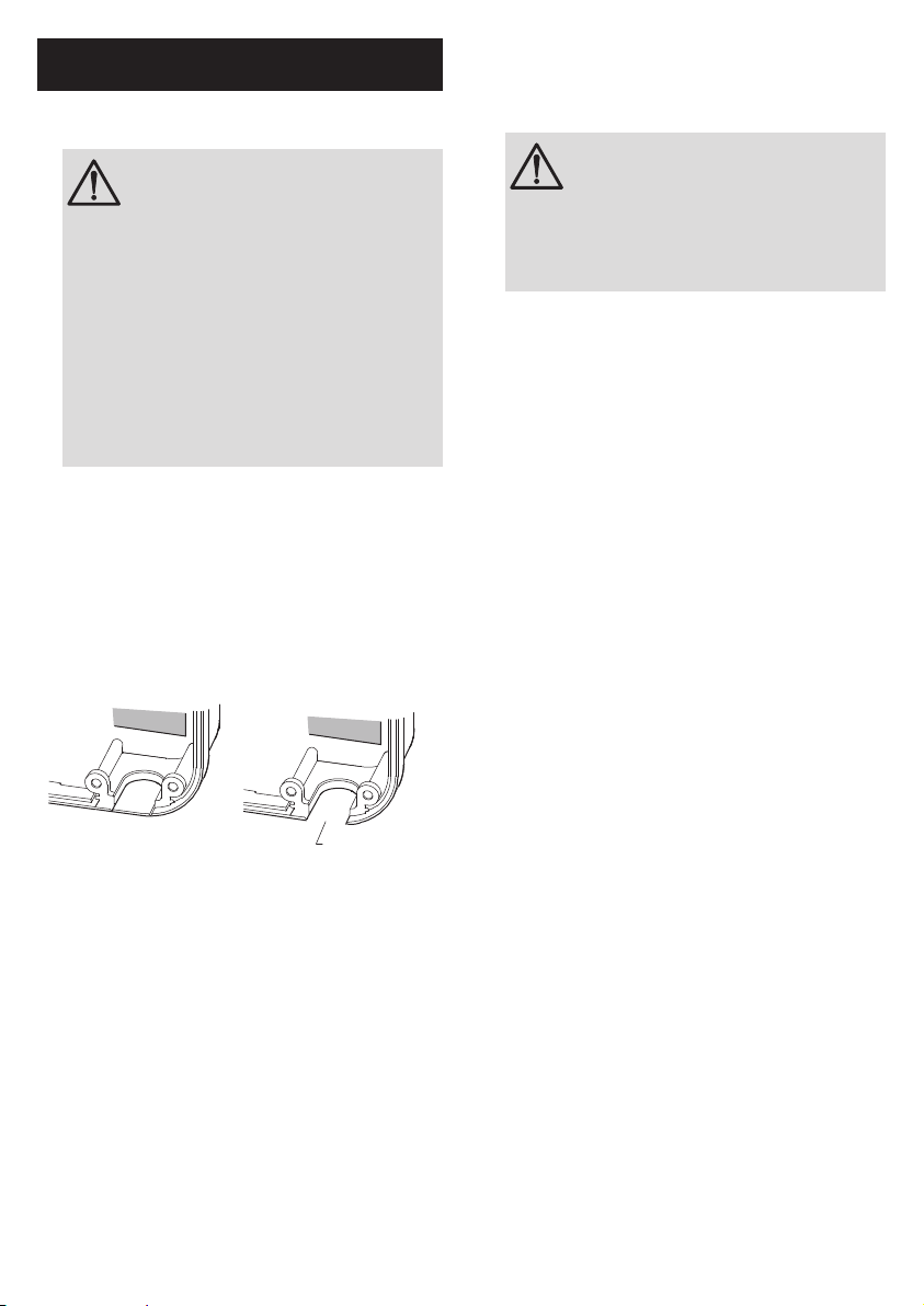
5.2 Installation requirements
Pipe entry
Plumbing entry can be from the rear (preferred) or
from the bottom. The backplate has a cut out position
to suit 15mm pipe. When opting for bottom entry
make the cut out before tting the backplate to the
wall - see gure 5 below.
Make cut-out
using sharp knife
Figure 5 – Plumbing cut-out
Water requirements
The installation must be in accordance with Water
Regulations. To ensure activation of the heating
elements, the handwash must be connected to a
mains water supply with a minimum running pressure
of 0.1 MPa (1 bar) and a maximum static pressure
of 0.7 MPa (7 bar). If static pressure exceeds 0.7
MPa (7 bar) t a pressure reducing valve to avoid
damaging the product. If in doubt, the pressure
should be checked taking account of other services
from the same water supply which could cause
the pressure to fall below the minimum. The water
supply can also be taken from a cold water storage
cistern provided there is a minimum head of 10m
above the product.

9
5.3 Choice of location
The product must be mounted on a at surface,
which covers the full width and length of the
backplate. It is important that the wall surface is at
otherwise difculty may be encountered when tting
the cover.
Ensure that the product is positioned over the basin,
if the PRD operates, water will eject from the bottom
of the product.
The outlet of the product acts as a vent and MUST
NOT be connected to any form of outlet ow control,
or any other tting not recommended by the
manufacturer.
WARNING
DO NOT t the product to the wall and
tile up to the case. It must be tted on to
a nished at and even wall surface. This
allows removal for servicing.
Position the product above the basin so that the
spray will be contained within the basin and at a
convenient height for hand washing see gure 7
below.
Main water supply
(Use rear entry when
it is possible)
130
200
PRD
outlet
Typical arrangement
Isolating stop valve
All dimensions in mm
Figure 7 – Handwash position over basin (or sink)
Multipoint Instantaneous unit
(use rear entry when it is
possible)
80A or 100A main switch
Meter
Meter ‘tails’
Consumer
unit
RCD (can be part of
the consumer unit)
Double pole isolating switch:
pull cord or wall mounted in accordance
with IEE regulations
Figure 6 – schematic of typical electrical layout
Fuses do not give personal protection against electric
shock. To enhance electrical safety a 30mA residual
current device (RCD) should be installed in all electric
handwash circuits. This may be part of the consumer
unit, or a separate unit.
Ensure that all terminal block connections are
sufciently tight.
Switch off the product immediately and isolate if
water ceases to ow during use.
Other electrical equipment e.g. extractor fans, must
not be connected to the product or its supply circuit.
To obtain full advantage of the power provided by the
product, use the shortest cable route possible from
the consumer unit to the product.
If your consumer unit has a rating below 80A, or if
there is no spare fuse way, then the installation will not
be straightforward and may require a new consumer
unit. A qualied electrician should install the new
consumer unit. It may be necessary to contact your
electrical supplier to upgrade your supply.
CAUTION
To enhance electrical safety a 30mA
residual current device (RCD) should be
installed in all electric handwash circuits.
This may be part of the consumer
unit or a separate unit. DO NOT use a
rewireable fuse, instead use a suitably
rated miniature circuit breaker (MCB)
or cartridge fuse. The handwash must
be connected to its own independent
electrical circuit.
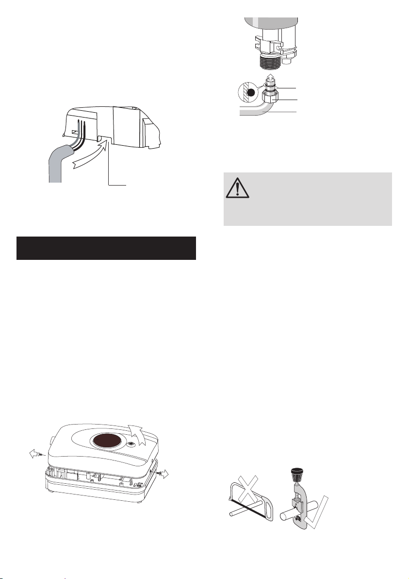
10
'O' rings
Plastic nut
(finger tight only)
Outlet pipe
Figure 10 – Fitting outlet spout
After choosing the correct site for the product, use
the backplate as a template and mark the two xing
holes.
WARNING
BEWARE OF CABLES AND PIPES
WHICH MAY BE BURIED IN THE WALL.
Drill holes using a 6.5mm diameter masonry drill.
Use plugs to suit the wall and use the xing screws
supplied.
6.2 Water connections
The outlet spout can be removed to ease installation.
The product has been designed for a 15mm water
pipe using the pusht connection - see gure 13.
Decide where to connect the cold water mains feed
to the product. Ensure the pipe you have selected
is not a gas pipe or a hot water pipe. Chrome and
stainless steel pipe is not recommended.
An isolating stop valve MUST be incorporated to the
main water supply to comply with Water Regulations
- see gure 7.
Cut all necessary pipework to length with a pipecutter
and not a hacksaw. This will minimise the swarf and
prevent damage to the sealing o-ring in the pusht
tting - see gure 11 below.
Figure 11 – Cutting pipes
A clearance of at least 130mm above and below the
product should be allowed for access to the cover
screws.
Cable entry can be from the rear (preferred) or from
the bottom. The backplate has cut-out positions to
suit the size of the cable. When opting for bottom
entry make the cut- out to suit the cable before tting
the backplate to the wall - see gure 8 below.
Make cut-out
using sharp
knife
Figure 8 – Bottom entry cable cut-out
6. Fitting Instructions
6.1 General
After reading the previous sections in this booklet
and choosing a good location for the product please
install, paying attention to the following plumbing,
electrical and commissioning sections.
TURN OFF the water and electrical supply.
The product is designed for bottom and rear entries
of water and electric cable. It is advisable to use the
rear entry (when it is possible), in order to obtain a
neater installation.
Unscrew the retaining screws and lift the cover from
the back plate - see gure 9 below.
Figure 7 Removing Cover
Figure 9 – Removing cover
Fit the outlet spout - DO NOT over tighten, nger
tight will be sufcient - see gure 10.

11
close
Figure 14 – Gear control valve
Turn the isolating stop valve on slowly and check for
leaks in all the pipework, rectify as necessary.
Turn off the isolating stop valve.
6.3 Electrical connections
WARNING
This product must be earthed.
CAUTION
When working on electrical components
ensure they are NOT LIVE. If in any
doubt, SWITCH OFF THE ELECTRICITY
SUPPLY.
A double-pole isolating switch having a contact
separation of 3mm in each pole MUST be
incorporated to the circuit - see paragraphs 5.2 p8.
The cable entry should have been decided before
tting the backplate - see 5.3 p9.
Remove the screws and clamping bar from the cable
clamp - see gure 2 p6.
Feed the cable in the backplate (unscrew backplate
for easy feeding if necessary).
Strip the outer sheath of the cable to a point about
5mm above the clamp, thus ensuring that the cable
is clamped across its outer sheath.
Strip the insulation from the cores and make
connections - see gure 2 p6.
Make sure that all the terminal block screws are
sufciently tight.
Ret the clamp bar.
Assemble the installation before making any
soldered joints to ensure that the pipe is the correct
length. DO NOT use jointing compounds on any pipe
ttings for the installation.
CAUTION
Remove the product before soldering the
connections.
It is essential to ush the pipe in order to clear debris,
particles of solder and swarf - see gure 12 below.
Figure 12 – Flushing the pipework
Turn the water off after ushing using the isolating
stop valve.
Connect the cold water supply pipe to the inlet of the
product, this is a push t - see gure 13 below.
35mm
Bottom entry Rear entry Copper compression
fitting shown - push fit stem
elbow can be used
Figure 13 – Pipe connection
Fit top and bottom screws and secure the backplate
to the wall ensuring that it is level. See gure 1 for
securing positions.
Close the product ow control valve by turning the
gear fully anti-clockwise.

12
6.4 Fitting cover
Fit outlet spout if required - see gure 10 p10.
Check that the ow control valve is fully closed by
turning the gear fully anti-clockwise.
Place the cover onto the back plate.
Secure the cover to the back plate using the screws
provided.
WARNING
This product must be earthed.
7. Commissioning
7.1 General
NOTE: The rst operation of the product is intended
to ensure the heater unit contains water before the
product is switched on.
7.2 Checklist before commissioning
Before turning on the electricity and mains water to
the hand wash ensure the torx adjusting screw is
turned fully anticlockwise – see gure 15 below.
7.3 Commissioning procedure
`Turn on the electrical supply and main water
supply at the isolating stop valve.
`Place hand in front of appliance sensor to
activate solenoid.
`When water ows constantly from spout turn
torx adjusting screw to an acceptable level of
ow, appliance will then start to heat water. (You
may have to place your hand in front of sensor to
keep water owing) adjust further for acceptable
heat.
`Leave torx adjusting key with customer.
8. Operation
8.1 General
Place hand in front of appliance sensor. After
approximately 15 seconds the water will start to heat.
Shut off the product by moving your hand away from
the sensor. The product is now ready to use.
The neon light will illuminate when the water is
heating.
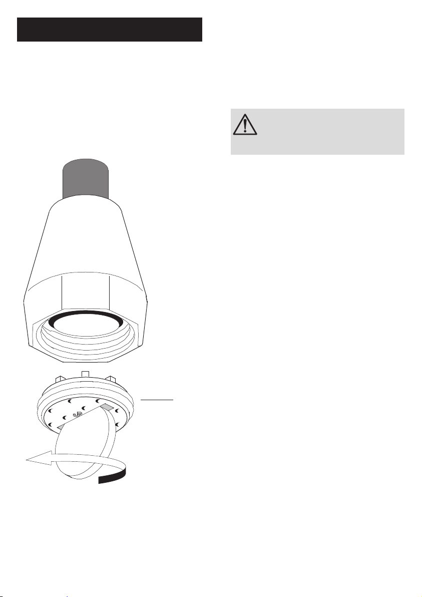
Sprayplate
To remove sprayplate
unscrew anticlockwise
using a coin.
Ensure all holes in
sprayplate are clear.
It is recomended to soak
the sprayplate overnight
in suitable descalant.
DO NOT OVERTIGHTEN
when refitting sprayplate.
Figure 15
13
9. Maintenance
9.1 General
It is recommended that the product casing be
cleaned using a soft cloth and that the use of abrasive
or solvent cleaning uids be avoided. It is advisable
that before cleaning, the isolating switch is turned off,
thus avoiding accidental operation of the product.
IT IS MOST IMPORTANT TO KEEP
THE SPRAYPLATE CLEAN IN ORDER
TO MAINTAIN THE PERFORMANCE
OF THE HANDWASH. The hardness
of the water will determine the
frequency of cleaning.
WARNING
This product must be earthed.
Sprayplate
To remove sprayplate
unscrew anticlockwise
using a coin.
Ensure all holes in
sprayplate are clear.
It is recomended to soak
the sprayplate overnight
in suitable descalant.
DO NOT OVERTIGHTEN
when refitting sprayplate.
Sprayplate
To remove sprayplate
unscrew anticlockwise
using a coin.
Ensure all holes in
sprayplate are clear.
It is recomended to soak
the sprayplate overnight
in suitable descalant.
DO NOT OVERTIGHTEN
when refitting sprayplate.
Figure 16 – Sprayplate

14
10. Troubleshooting
In the unlikely event of a problem, consult the trouble-
shooting chart below.
If you are unable to remedy the problem, contact
your installer in the rst instance.
Do not attempt any electrical or plumbing
work unless you are competent to do so.
If you still cannot solve the problem,
please contact the manufacturer.
Inspection
It is advisable that, in the interests of safety, the
product and its electrical installation is checked by a
competent electrician at least every two years.
10.1 Decommissioning procedure
`Isolate electrical supplies and make safe
`Isolate the water supply
`Drain the product
`Remove the product
`Cap pipework
Environmental information
Handwash products are manufactured from many
recyclable materials.
WEEE Declaration
Disposal of Waste Equipment by Users in Private
Households in the European Union.
This symbol on the product indicates that this product
must not be disposed of with your other household
waste. Instead, it is your responsibility to dispose
of your waste equipment by handing it over to a
designated collection point for the recycling of waste
electrical equipment. The separate collection and
recycling of your waste equipment at the time of
disposal will help to conserve natural resources and
ensure that it is recycled in a manner that protects
human health and the environment. For more
information about where you can drop off your waste
equipment for recycling, please contact your local city
ofce, your household waste disposal service or the
company where this product was purchased.
Symptom Possible cause Remedy
1. No water ows
with valve open
A. Water supply turned off Turn on water supply
B. Unit frozen Turn OFF ELECTRICITY at isolating switch
and contact installer. DO NOT USE THE
HANDWASH.
C. Spout blocked Clean sprayplate - see 9.1 p13
D. Filter blocked Clean lter
2. Water too cold A. Water control at wrong setting Adjust as per commissioning notes
B. Water ow too high Adjust as per commissioning notes
C. Electricity off Turn on electricity at isolating switch
D. Poor ow Check inlet pressure
3. Water too hot A. Temperature control at wrong
setting
Adjust as per commissioning notes
B. Spout partially blocked Clean sprayplate - see see 9.1 p13
C. Isolating valve not fully open Open isolating valve
D. Filter blocked Clean lter
4. Water runs from
pressure relief
device
A. Spout blocked Clean sprayplate - see see 9.1 p13, push
plastic plunger up and back in place
B. Spout not blocked Call a service engineer as there may be a
problem with internal parts

15
11. Spare parts
The following comprehensive list of spare parts is
available for your product. Please refer to the rating
label on the side of your product before ordering to
ensure the correct spare part is obtained.
DO NOT REPLACE WITH PARTS NOT
RECOMMENDED AS THIS WILL INVALIDATE
YOUR WARRANTY AND MAY RENDER THE
INSTALLATION DANGEROUS.
Warranty
Warranty & Service Policy
This product is covered against faulty materials and
manufacture for a period of two years from the date
of purchase provided that:
`The product has been installed by a competent
person in accordance with the Installation, User
instructions, all relevant Codes of Practice,
Regulations in force at the time of installation
and that all necessary controls and safety valves
have been tted correctly.
`Any valves and controls are of the Heatrae
Sadia recommended type and specication.
`The product has not been modied or tampered
with in any way, and has been regularly
maintained as detailed in the Installation and
User Instructions.
`The product has been used only for heating
potable water.
The product is not covered against damage by frost,
and the inner container with integral heating element
is not covered against excessive scale build-up.
This warranty in no way affects the statutory rights
of the consumer.
The policy of Heatrae Sadia is one of continuous
product development and, as such, we reserve the
right to change specications without notice.
Description Code No
1 Heat Exchanger Assembly 3.1kW 95 608 003
2 Spout-3.1kW 95 604 002
3 Cut-out - 3.1kW 95 612 029
4 Cut-out - 3.1kW (one shot) 95 612 031
5Valve/Pressure Switch Assembly
- 3.1kW
95 605 052
6Cover Assembly 95 614 092
7Neon Assembly 95 615 056
8 Micro switch 95 613 003
9 Filter 95 607 107
10 Pressure Relief Device 95 607 108
11 PCB 95 615 024
12 Solenoid Valve 95 605 058
13 Torx Adjustor 95 607 037
6
2
10
11
13
912
5
4
3
8
7
1
Please follow us online:
Electric Water Heating Co.
2 Horsecroft Place
Pinnacles
Harlow
Essex CM19 5BT
Tel: 0845 055 3811
E-Mail: [email protected]
SPD
Special Product Division
Units 9 & 10
Hexagon Business Centre
Springeld Road
Hayes
Middlesex UB4 0TY
Tel: 020 8606 3567
Parts Center
Tel: 0344 292 7057
www.partscenter.co.uk
Newey & Eyre
Unit 3-5 Wassage Way
Hampton Lovett Ind. Estate
Droitwich, Worcestershire
WR9 0NX
Tel: 01905 791500
Fax: 01905 791501
UK Spares Ltd
Unit 1155
Aztec West
Almondsbury
Bristol BS32 4TF
Tel: 01454 620500
Alternatively contact your
local supplying merchant
or wholesale branch or use
our online stockist nder at
www.interpartspares.co.uk
PRODUCT RANGE
Full specication details on all our products are available to download from our website.
To support our corporate responsibility and sustainability charters and reduce our
printed material we encourage you to download product brochures from our website.
In designing these les we have taken into account the need to access data on screen.
If you would like to receive a printed copy of our full product catalogue please call
our literature hotline on 01603 420127.
Heatrae Sadia may introduce modications to their products from time
to time. Consequently, the details given in this brochure are subject to alteration
without notice.
OUR NATIONWIDE NETWORK OF CUSTOMER SUPPORT ENGINEERS
Heatrae Sadia has its very own dedicated nationwide network of highly trained
customer support engineers so you can have peace of mind that we’re always
here to help.
2
2 YEAR
WARRANTY
SPECIFICATION ADVICE HOTLINE
t| 01603 420220 e | speci[email protected]
AFTER SALES SERVICE
t| 0344 871 1535 e| customer[email protected]
w | heatraesadia.com
16
PN 36 00 6009 Issue 5
©Heatrae Sadia 2015
Table of contents
Other Heatrae Sadia Dryer manuals

Popular Dryer manuals by other brands


Samung
Samung DVG50R5400 Series user manual

Samsung
Samsung DV9 M82 Series user manual

Indesit
Indesit G74V Use and care & installation instructions

Alliance Laundry Systems
Alliance Laundry Systems DV6000WG Installation & operation

montpellier
montpellier MSD2800W Installation and operating instructions

LG
LG DVH5-08W owner's manual


