Hedman HF100 Instruction and safety manual
Printed in U.S.A.
Form No. 198557HF
HEDMAN
®
Form No. 198557HF
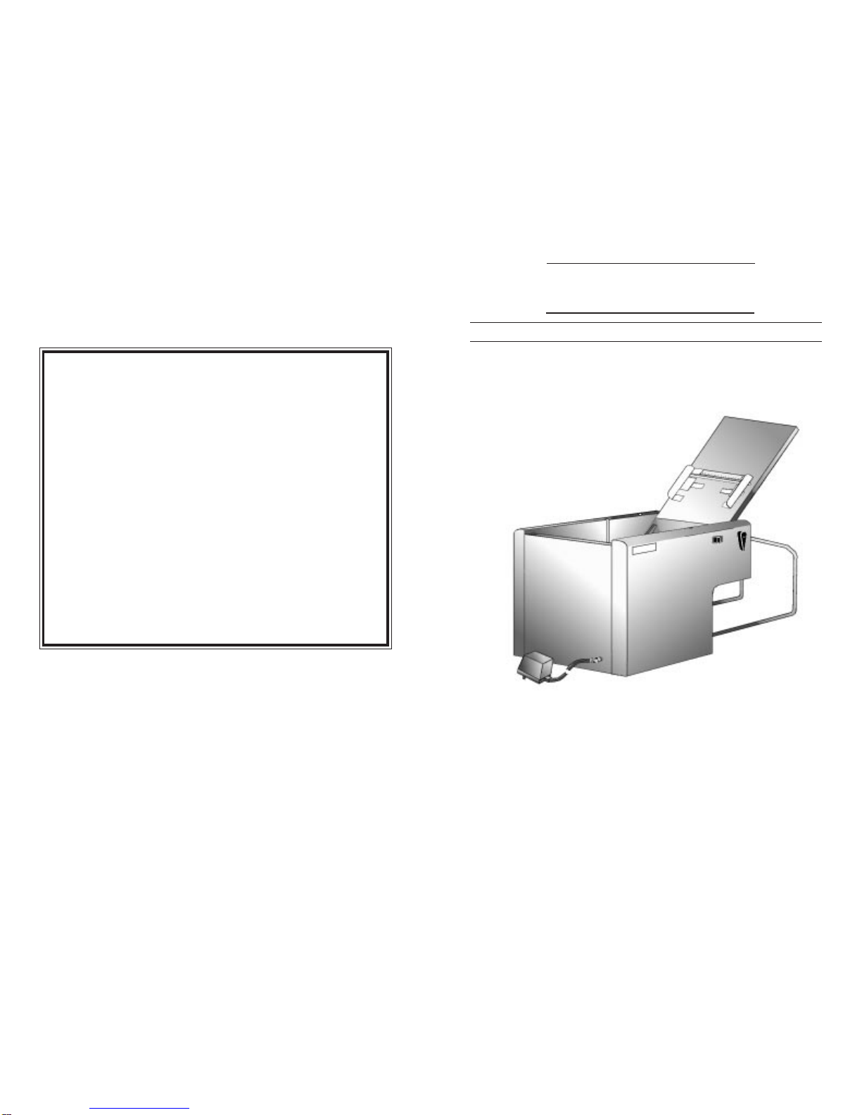
HF100 FOLDER
OPERATING & SERVICE MANUAL
THE HEDMAN COMPANY
189 Gordon St.
Elk Grove Village, IL 60007
800-872-2788
The HEDMAN Company • 189 Gordon St. • Elk Grove Village, IL 60007 • 800-872-2788
NOTICE
Proprietary Information - this material is not to be reproduced by
any means or disclosed in any way without prior written approval by
THE HEDMAN COMPANY.
Disclaimer - this material is subject to change without notice and
should not be construed as a commitment by THE HEDMAN
COMPANY.Neitherexpressnorimpliedwarrantyismaderegarding
the procedures herein, their merchantability, or fitness for any
specific application.
These procedures are provided solely on an "as-is" basis, and the
customer agrees to assume any costs arising from use or misuse of
the material, including all correction and damages consequential or
incidental.
THE HEDMAN COMPANY - ALL RIGHTS RESERVED.
©2001 The Hedman Company

2
TABLE OF CONTENTS
Page
4 SPECIFICATIONS
5 COMPONENTS & CONTROLS
6 AUTOMATIC FOLDING
7 MANUAL FOLDING
8-10 MAINTENANCE
8 Removing Cartridge
9 Cleaning Feed Roller
10 Adjusting Separator
11-12 SERVICE
11 Replacing Separator
12 Replacing Feed Roller
13-19 PARTS DRAWINGS & PARTS LISTS
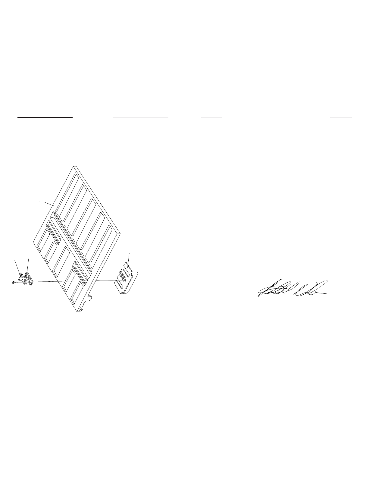
13 Fold Plates
14-15 Drive Assemblies
16-17 Covers & Knobs
18 Feed Tray
19 TROUBLESHOOTING
19
TROUBLESHOOTING
1. FOLD QUALITY
A. Documents skew - crooked folds
1. As folder runs, adjust PAPER GUIDES slightly to correct the skew.
2. Re-position paper in HOPPER. Hold HOPPER LEVER open and load
paper squarely and centered. Slowly release HOPPER LEVER.
3. Too much paper in folder. Stop folding and remove some paper.
Maximum paper stack is 5/8" (16 mm).
4. Remove and clean CARTRIDGE.
WARNING: Turn POWER SWITCH off and unplug POWER CORD
before removing CARTRIDGE.
5. Clean FEED ROLLER.
B. Fold dimensions are incorrect
Remove CARTRIDGE.
WARNING: Turn POWER SWITCH off and unplug POWER CORD
before removing CARTRIDGE.
NOTE:
Use compressed air to blow obstructions out of FOLD PLATES.
2. CLEARING PAPER JAMS
A. Remove CARTRIDGE and clean (refer to instructions on page 8).
B. Clean FOLD PLATES using compressed air.
3. DOUBLE FEEDING
A. Clean FEED ROLLER using alcohol.
B. Adjust SEPARATOR (refer to instructions on page 10).
C. Replace FEED ROLLER and SEPARATOR (refer to instructions on pages
11 and 12).
4. NOT FEEDING - IRREGULAR FEED
A. Change paper if possible. Some types of paper do not feed well.
B. Clean FEED ROLLER using alcohol.
C. Replace SEPARATOR and check FEED ROLLER (refer to instructions on
page 11).
D. MOTORS run, FEED ROLLER does not drive, but rotates freely.
1. Replace "O" RING, page 15, #19.
3
18
DECLARATION OF CONFORMITY
(Manufacturer's Declaration according to EC Machinery Directive
89/392/EEC, Annex II A)
Applicant: The Hedman Company
189 Gordon St.
Elk Grove Village, IL 60007
Manufacturer: AUTOMECHA Mfg.
Route 12
Oxford, NY 13815
The manufacturer declares that the following described machine complies with the
appropriatebasicsafety and health requirementsofthe EC Machinery Directive89/
392/EEC, based on its design and type. In case of alteration of the machine, not
agreed to by the manufacturer, this declaration will lose its validity.
Equipment Type: Paper Folding Machine
Model Designation: HF100-IN, HF100-UK.
Description: Rated Voltage - 15 VDC (Output of stand-alone power supply)
Rated Input Power - 1.4A
Applicable EC Directives: EC Machinery Directive (89/392/EEC)
EC Low Voltage Directive (72/23/EEC)
EC Electromagnetic Compatibility (89/336/EEC)
Applicable Standards: EN 292, EN294, EN 60950, EN 55014
(C.I.S.P.R. 14). EN 50082-1. IEC 801
Date/Authorized Signature: 20 April, 2001
Title of Signatory: Agent
FEED TRAY
ITEM # PART # DESCRIPTION
1 6F1582 COVER, TOP SCREENED
1 6F 1582IN COVER, TOP SCREENED (FOR A-4 PAPER)
2 3F1544 PAPER GUIDE
3 3F1522 GUIDE SPRING
4 3F1521 GUIDE RETAINER
4
3
1
2

SPECIFICATIONS
POWER: 15V, D.C.(14.8)/1.4 amp/external; wall mountable;
power pack with internal circuit breaker
UL, CSA & FCC approved
120/220/240 V.A.C., 50/60 HZ
International approvals TUV, GS, CE
WEIGHT: 20 lbs. (9.0 kg) / 26 lbs. shipping (11.8 kg)
SPEED: up to 200 sheets per minute
PAPER SIZE: 8.5" x 11" (or A4 European)
PAPER
WEIGHT: 16 to 24 lb. bond/up to 60 lb. offset (50 to 180 GSM)
HOPPER
CAPACITY: up to 150 sheets
MANUAL
FEED
CAPACITY: 3 sheets stapled or loose
FOOTPRINT: 12" (30.4 cm) long x
13" (33 cm) wide x
8.75" (22.2 cm) high
417
COVERS & KNOBS
ITEM # PART # DESCRIPTION
1 3F1618 INDICATOR, DIAL
2 6F1549-02 COVER ASSEMBLY
3 3F1609 LEVER
4 7F1596 SEPARATOR SHAFT ASSEMBLY
5 3P1911 RUBBER FOOT
6 3F1553 POWER SUPPLY (120V)
6 3F1643 EUROPE POWER SUPPLY (220V)
6 3F1642 UNITED KINGDOM POWER SUPPLY (220V)
7 3F1549-01 COVER, NON-OPERATOR SIDE
8 7F1656 ON/OFF/JOG SWITCH AND HARNESS
9 7F1571 POWER JACK ASSEMBLY - NOT SHOWN
10 3F1657 LABEL, SWITCH - NOT SHOWN
11 3F1619 SHIPPING CARTON, MACHINE - NOT SHOWN
12 3F1607 CORK PATCH
13 3F1592 SPRING WINDER
(Not shown - only on machines with Serial # 300D1471 and lower)
14 3F1591 SPRING
(Not shown - only on machines with Serial # 300D1471 and lower)
15 3F1653 SPRING, FEED DOOR
(Only on machines with Serial # 300D1471 and higher)
16 3F1541 BASE
17 3F1599 PAPER DEFLECTOR
18 3F1586 FEED DOOR
19 3F1539 FRONT BAFFLE
20 6F1545 LARGE END
21 3F1546 INNER COVER
22 3F1585 PAPER END STOP
23 3F1506 PAPER DEFLECTOR EXTRUSION

COMPONENTS & CONTROLS
5
POWER CORD
SEPARATOR
ADJUSTMENT
HOLE
POWER
SWITCH
GUIDE
ROLLERS
OPERATING
MANUAL
GUIDE FINGERS
FEED ROLLER
PAPER GUIDES
HOPPER
LEVER
RECEIVING
RACK
PAPER WIDTH
SCALE
FEED
TABLE
HOPPER
WARNING
The outlet socket is the
main power. It must be
located near the
equipment and easily
accessible.
16
COVERS & KNOBS
18
19
16
20
21
17
23
22
5
6
3
82
1
12
4
15
7
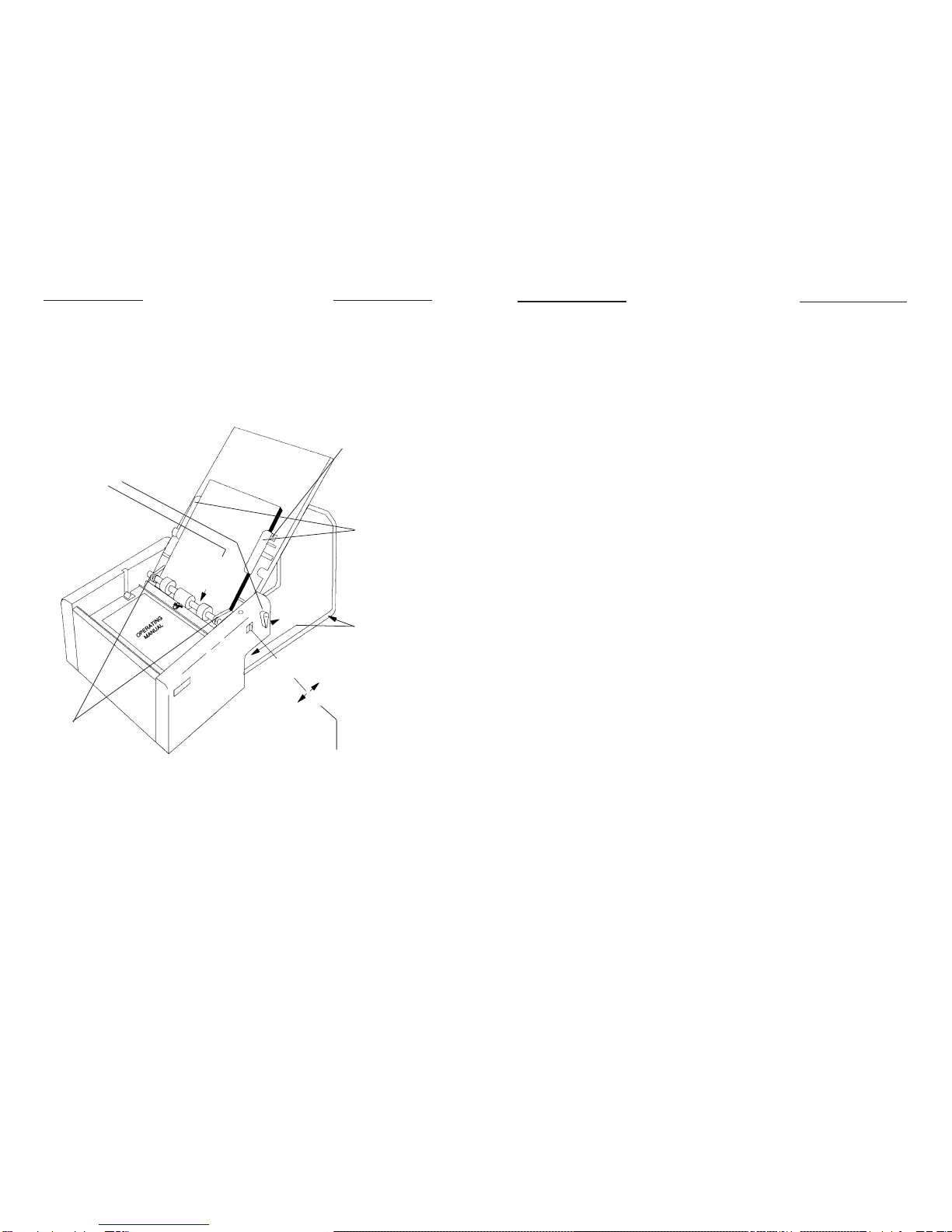
AUTOMATIC FOLDING
(Stack of sheets up to 5/8" (16 mm) high)
6
3. Slide PAPER
GUIDES snugly
against stack.
2. Center paper on
FEED TABLE and
release HOPPER
LEVER.
1. Hold HOPPER LEVER
open (right) and load
neatly stacked and
squared paper into
HOPPER.
4. Position
RECEIVING
RACK by placing
a folded sheet
against the folder
and sliding the
rack 1" to 2" from
the sheet.
6. Turn POWER SWITCH on.
Turn POWER SWITCH off
when you are finished
folding.
5. Slide
GUIDE
FINGERS
snugly
against
stack.
HOPPER
POWER
SWITCH
ON JOG
OFF
15
DRIVE ASSEMBLIES
ITEM # PART # DESCRIPTION
1 3F1559 GEAR (24T 20PA 24P)
2 7F1525 FEED ROLL ASSEMBLY
3 3F1536 PULLEY, FEED ROLL
4 3F1601 GUIDE, FRONT
5 3F1581 SPRING, CLUTCH
6 3F1602 BUSHING, SPLIT
7 3F1608 ROLLER, GUIDE
8 3F1525 ROLLER, FEED
9 7F1519 GEAR ASSEMBLY
10 3P1916 MICRO SWITCH
11 3F1556 MOTOR
12 3F1511-02 PRESSURE LEVER (OPERATOR SIDE)
13 3F1511-01 PRESSURE LEVER (NON-OPERATOR SIDE)
14 3F1514-01 SPRING, PRESSURE LEVER (NON-OPERATOR SIDE)
15 3F1514-02 SPRING, PRESSURE LEVER (OPERATOR SIDE)
16 7F1551 CARTRIDGE ASSEMBLY
17 3F1594 HOLDER, SQUARE SHAFT
18 3F1510 BEARING RETAINER SHORT
19 3F1637 “O” RING
20 3F1603 PULLEY, SMALL FEED
21 3F1557 BELT, 1/5 PITCH (134XL037)
22 3F1555 PULLEY, DRIVE 26T
23 7F1526 2 STEP PULLEY ASSEMBLY
24 3F1558 BELT, 1/5 PITCH (148XL037)
25 3F1554 PULLEY, MOTOR 10T
26 3F1552 BEARI NG
27 3F1543 RECEIVING RACK
28 05-0795-00 CAM SWITCH
29 02-1598-02 RUBBER "O" RINGS

7
SLOT
MANUAL FOLDING
(1 to 3 sheets stapled or loose)
1. Close FEED TABLE
onto top of folder.
2. Slide PAPER
GUIDES as far
apart as possible. 3. Insert sheet(s)
squarely into
SLOT and let
them rest on your
finger as shown.
Do not hold
sheet(s).
4. Turn POWER
SWITCH to JOG
until paper is folded.
14
DRIVE ASSEMBLIES
19
NON-OPERATOR
SIDE
OPERATOR
SIDE
20
21
22
18
23
14
26
3
17
27
24
29
25
11
13
12
47
857
6
4
17
28
10
9
16 1
18
813
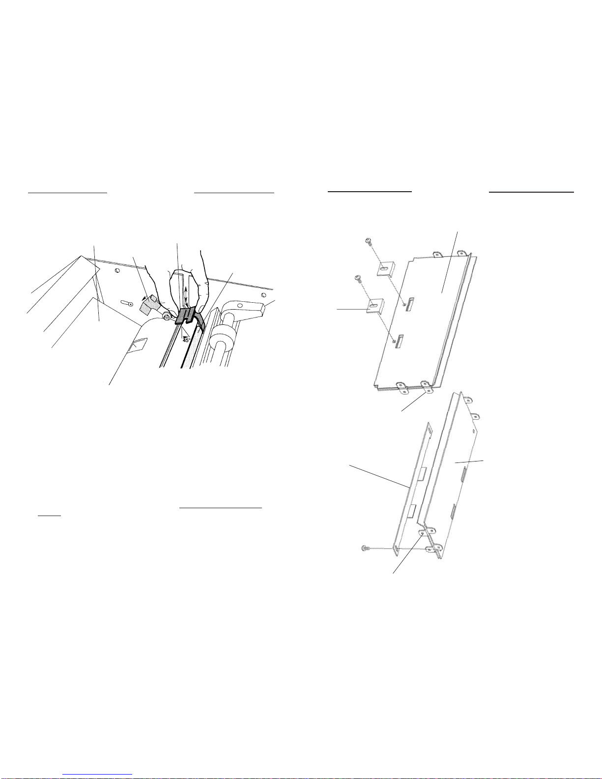
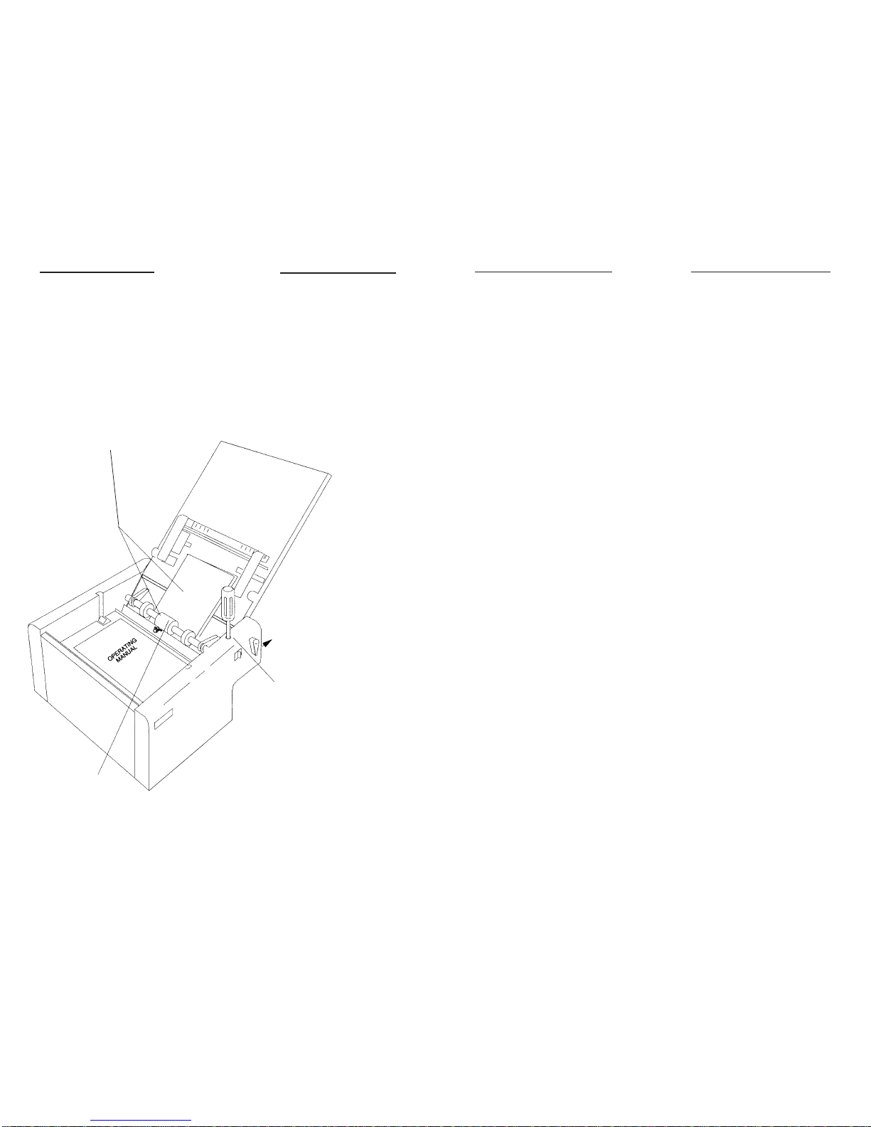
MAINTENANCE
Removing CARTRIDGE
WARNING: Turn POWER SWITCH off and unplug POWER CORD before
removing CARTRIDGE.
To Remove CARTRIDGE:
1. Open TOP and INNER COVERS.
2. Pull back RED PRESSURE LEVERS.
3. Remove CARTRIDGE by sliding it up and out of the folder in the slot.
When installing CARTRIDGE, the RUBBER ROLLER must be held at a 45°
angle toward the feed end of folder (refer to illustration above).
4. Once in place, push the CARTRIDGE down to make sure it is in place and
leveled.
5. Close RED PRESSURE LEVERS.
6. Close TOP and INNER COVERS. Important: INNER COVER must be closed
or folder will not run.
NOTE:
If CARTRIDGE has wear marks, cuts, etc., it must be replaced.
(Part # 7F1551).
INNER
COVER RED
PRESSURE
LEVER
CARTRIDGE
RUBBER
ROLLER
ITEM # PART # DESCRIPTION
1 04-0364-00 "A" OUTER FOLD PLATE
2 04-0365-00 "A" INNER FOLD PLATE
3 04-0313-00 "A" STOP
4 04-0427-00 "B" OUTER FOLD PLATE
5 04-0426-00 "B" INNER FOLD PLATE
6 04-0314-00 "B" STOP
FOLD PLATES
2
1
3
4
5
6

9
12
MAINTENANCE
Cleaning FEED ROLLER
To clean FEED ROLLER:
1. Turn POWER SWITCH off.
2. Using a cloth and alcohol, clean entire FEED ROLLER.
3. Allow FEED ROLLER to dry completely before folding.
FEED ROLLER
SERVICE
Replacing FEED ROLLER
If the FEED ROLLER is visibly worn or is chunking apart, it must be replaced. When
changing the SEPARATOR, replace the FEED ROLLER as well.
To change the FEED ROLLER:
1. Turn POWER SWITCH off and unplug POWER CORD.
2. Remove SIDE COVERS.
3. Remove DRIVE BELT and PULLEY.
4. Removethe"E"RINGSontheinsideof frames nexttotheOILITEBUSHINGS.
NOTE:
OILITE BUSHINGS are pressed in and removal is not necessary.
5. LoosenGUIDE ROLLERS and slidetheshaft 3 to 4inches to the operator side
so GUIDE FINGER, BUSHING and GUIDE ROLLER can be removed.
6. Remove the "E" RING located next to the FEED ROLLER. Slide the FEED
ROLLER off as well as the CLUTCH SPRING. Inspect inside of CLUTCH
SPRINGfor wear. Ifa"flat"wearareahasappearedinstead of normal rounded
coils, replace the CLUTCH SPRING (part# 3F1581).
7. Cleantheshaftandlightlylubricatewithalightmachineoil,theareaontheshaft
where the CLUTCH and FEED ROLLER are mounted. Reassemble theFEED
SHAFT.
8. TheFEEDROLLERshouldspineasilyinonedirectionand"lock-up"whenspun
intheoppositedirection.NOTE:
Iftherollerdoesnot"lock-up",thereistoomuch
lubrication between CLUTCH SPRING and FEED SHAFT.
9. Re-assemble shaft into frame.
10. Lightly oil the OILITE BEARINGS for the FEED SHAFT and make sure the
FEED SHAFT spins freely in the side frames.
11
10
The SEPARATOR must be set to feed one sheet of paper at a time.
WARNING: Turn POWER SWITCH off and unplug POWER CORD before
making adjustment.
To adjust SEPARATOR:
1. Clean FEED ROLLER before adjusting SEPARATOR. (Refer to page 9.)
2. Fold a strip of standard (20# bond) paper in half. Hold HOPPER door open.
Turning the FEED ROLLER by hand, feed the sheet under the roller.
3. Hold the FEED ROLLER so it cannot turn. Pull the strip out. It should pull out
with some difficulty.
5. To adjust FEED ROLLER
separation, insert #1 Phillips
screwdriver into SEPARATOR
ADJUSTMENT HOLE. Turn
screwdriver
clockwise
to increase
pressure and
counterclockwise
to de-
crease pressure. Adjust FEED ROLLER to
satisfy Steps 1 thru 3. If the pressure setting is
correct, folder will run quietly and easily. If these
adjustments do not correct the condition, the FEED
ROLLER and/or SEPARATOR must be replaced.
Refer to Pages 11 and 12.
FEED ROLLER
Hold
Open
MAINTENANCE
Adjusting SEPARATOR
4. Repeat Steps 1
and 2 using a
sheet of paper
folded in thirds.
With three
thicknesses of
paper you must
pull hard enough
to almost tear the
paper.
SERVICE
Replacing SEPARATOR
TheSEPARATOR(locatedbelowtheFEEDROLLER) isavery important partofthe
automaticfeedingsystem.KeepingtheSEPARATORadjustedasitwears(seePage
10)will insure proper operation.Ifthe adjustment screws runout of travel and canno
longerbeadjusted,theSEPARATORHOLDERASSEMBLY(part#7F1596)mustbe
replaced. It is also recommended that the FEED ROLLER (part # 3F1525) and
CLUTCH SPRING (part # 3F1581) be replaced.
To change the SEPARATOR:
1. Turn POWER SWITCH off and unplug POWER CORD.
2. RemovebothSIDE COVERS. NOTE:
The folddialsmustberemoved.
Observe
the alignmentof dialsand tightnessof ACORNNUT for dialtension. Remember
to reconnect the POWER SWITCH.
3. Removethe PAPERDEFLECTOR(withstatic brushattached)atthe outputend
of folder by removing the screws in the side frame.
4. Remove theplastic FEED SHAFTPULLEY on the non-operatorside and remove
thesquareSHAFTHOLDERonbothsidesaswellastheSEPARATORADJUST-
ING SCREW and SPRING.
5. Remove the loose SEPARATOR SQUARE SHAFT ASSEMBLY through the
outputend of thefolder.Turntheshaft so thepinonthe non-operator sideclears
the keyhole.
6. Install the new SEPARATOR SHAFT ASSEMBLY the same way old assembly
was removed.
7. Assemble the SQUARE SHAFT HOLDER on non-operator side first. NOTE:
Make sure the SEPARATOR PATCH is positioned to fit through the hole under
the FEED ROLLER. The SQUARE SHAFT should slide through the slots with
little or no interference.
8. Re-assemble SEPARATOR ADJUSTMENT ASSEMBLY and re-adjust the
SEPARATOR using instructions on Page 10.
Table of contents
Other Hedman Paper Folding Machine manuals


