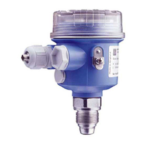
Hegwein FD Series User manual

Inhaltsverzeichnis
Operating Manual
Pressure switch
for gas, air and emissions
FD…
©
Hegwein GmbH
Am Boschwerk 7
70469 Stuttgart, Germany
Before first use, read the operating manual!
Tel.: +49 (0)711 13 57 88-0
Fax: +49 (0)711 13 57 88-5
www.hegwein.de
Status: 04-2016

Pressure switch FD…
Contents
- 2 - Status: 04-2016
1General .......................................................3
1.1 Information on the operating manual...........3
1.2 Explanation of symbols................................3
1.3 Liability disclaimer .......................................4
1.4 Copyright protection ....................................5
1.5 Warranty regulations ...................................5
1.6 After-sales service.......................................5
2Safety..........................................................6
2.1 Owner’s responsibility..................................6
2.2 Operating personnel....................................7
2.2.1 Requirements ..............................................7
2.2.2 Unauthorized persons .................................8
2.3 Intended purpose of the equipment.............8
2.4 Personal protective gear..............................9
2.5 Special dangers.........................................10
2.6 Securing against unauthorized switching
use 10
2.7 Response in case of danger or accident...11
3Transport, packaging and storage ........12
3.1 Safety instructions for transport.................12
3.2 Transport inspection..................................12
3.3 Packaging..................................................12
3.4 Storage conditions.....................................13
4Specifications ..........................................14
4.1 Type designation with type key .................14
4.2 Pressure switch .........................................15
4.3 Dimensional drawing.................................16
4.4 Rating plate ...............................................16
4.5 Service life.................................................17
5Functional characteristics and
structure ...................................................18
5.1 Functional characteristics ..........................18
5.2 Structure ....................................................18
6Installation and initial commissioning...20
6.1 Safety.........................................................20
6.2 Installation..................................................20
6.3 Electrical connection..................................22
6.3.1 Cable inlets through cable glands Pg
13,5............................................................22
6.3.2 Special design with plug and socket
connection FD.../0B0000 ...........................23
6.3.3 Setting the switch-on point acc. the
switching pressure.....................................24
6.3.4 Control the switch-on point acc. the
switching pressure.....................................25
7Maintenance.............................................26
7.1 Safety.........................................................26
7.2 Conditions for maintenance work ..............26
7.3 Maintenance, general ................................27
8Troubleshooting.......................................28
8.1 Safety.........................................................28
8.2 Troubleshooting table ................................29
9Dismantling / Disposal ............................30
9.1 Safety.........................................................30
9.2 Dismantling................................................30
9.3 Disposal .....................................................31
10 Annex........................................................32
10.1 EC type examination certificate.................32
10.2 EU Declaration of conformity.....................34

Pressure switch FD…
General
Status: 04-2016 - 3 -
1 General
1.1 Information on the operating manual
This operating manual provides important information on working
with the pressure switch. Safe working can only be ensured by
adhering to all the safety remarks and instructions provided.
In addition, the locally applicable accident prevention laws and
general safety regulations must be followed.
Read the operating manual carefully before using the pressure
switch the first time. These instructions form an integral part of the
product and must be kept near the equipment at all times within
easy reach for personnel.
When the pressure switch is transferred on to third parties, it must
always be accompanied by the operating instructions.
The illustrations in this operating manual are intended to aid
understanding of the content. They are not necessarily true to
scale and may differ slightly in some details from the actual
configuration of the pressure switch.
1.2 Explanation of symbols
Warning instructions
Warning instructions are indicated in this operating manual by
symbols. The remarks are introduced by the use of signal words
which indicate the degree of severity of the hazard.
The instructions must be adhered to without fail and acted upon
prudently in order to prevent accidents, personal injury or material
damage.
DANGER!
… denotes a hazardous situation which results in
death or serious injury unless prevented.
WARNING!
… denotes a hazardous situation which could result
in death or serious injury unless prevented.
CAUTION!
… denotes a hazardous situation which could result
in minor or slight injury unless prevented.
NOTE!
… denotes a hazardous situation which could result
in material damage unless prevented.

Pressure switch FD…
General
- 4 - Status: 04-2016
Recommendations
REMARK!
… highlights useful recommendations and
information designed to permit efficient, trouble-
free operation.
Special safety remarks
In order to draw attention to special hazards, the following symbol
is used in conjunction with safety remarks:
DANGER!
Fatal danger due to electrical current!
… denotes a potentially fatal situation due to
electrical current. Failure to adhere to the safety
instructions can give rise to the danger of serious
injury or death.
The work to be performed may only be carried out
by a suitably qualified electrician.
1.3 Liability disclaimer
All instructions and remarks contained in this operating manual are
collated taking into account applicable standards and regulations,
the state of the art and our many years of experience and
expertise.
The manufacturer is consequently unable to accept any liability for
damage caused as a result of:
Failure to adhere to the instructions
Use for any other than the designated purpose
Deployment of untrained personnel
Internally executed modifications or conversion work
Technical modifications
Use of unapproved spare parts
The actual scope of the delivery may differ in some details from the
explanations and illustrations provided here in the case of special
versions, where additional optional features are made use of or
due to the latest technical modifications.
Otherwise, the obligations agreed in the Supply Agreement, the
General Terms and Conditions and the Manufacturer’s Conditions
of Supply and the statutory regulations in force at the time of
conclusion of contract shall be applicable.

Pressure switch FD…
General
Status: 04-2016 - 5 -
1.4 Copyright protection
These operating instructions may not be shared with third parties.
They are exclusively intended for those operating the pressure
switch and may not be made available to third parties without the
prior written consent of the manufacturer.
REMARK!
The information, texts, drawings, illustrations and
other representations are protected by copyright
and are subject to industrial property rights.
Utilization for any other than their intended purpose
renders the perpetrator liable to prosecution.
The contents of all or part of these operating instructions may not
be duplicated in any form, nor may they be used and/or
communicated to any third party without the written consent of the
manufacturer. Any breach of this obligation shall render the
perpetrator liable to compensation of damages, without prejudice
to any further-reaching claims.
1.5 Warranty regulations
The warranty regulations are provided as a separate document in
the General Terms and Conditions.
1.6 After-sales service
For any technical information, consult our after-sales service.
Information can be obtained at any time by phone, fax, e-mail or
Internet. For the manufacturer’s address, see the cover sheet on
the table of contents.
Our employees are always open to feedback and comments
related to all of our products which could be of use in the continual
and improvement of our products.

Pressure switch FD…
Safety
- 6 - Status: 04-2016
2 Safety
This section provides an overview of all important safety aspects
for optimum protection of personnel as well as safe, trouble free
operation.
Failure to observe the operating instructions and safety remarks
contained in this manual can cause serious injury.
This information described minimum requirements, local situations
and regulations may call for a wider scope.
2.1 Owner’s responsibility
As the pressure switch is used commercially, the owner of the
pressure switch is obliged to adhere to occupational safety
regulations as well as any other applicable directives, legislation
and standards.
Alongside the occupational safety remarks contained in these
operating instructions, the safety, environmental and accident
prevention regulations governing the field of application of the
pressure switch must be adhered to, whereby the following
regulations in particular apply:
The owner must be aware of the valid occupational safety
regulations.
The owner must clearly regulate and define fields of
responsibility for installation and maintenance.
The owner must ensure that all employees involved in working
with the pressure switch have read and understood the
operating instructions.
Furthermore, the owner must provide personnel training at
regular intervals and inform staff of potential hazards.
As the owner is also responsible for ensuring that the pressure
switch is always in good technical working order the following
requirements additionally apply:
The owner must regularly check that all safety devices are fully
functional and complete.
The owner must provide the necessary protective gear for
personnel.

Pressure switch FD…
Safety
Status: 04-2016 - 7 -
2.2 Operating personnel
2.2.1 Requirements
WARNING!
Danger of injury due to insufficient qualification
Incorrect handling of the equipment can result in
severe personal injury and material damage.
–Only allow activities to be performed by suitably
qualified specialist personnel.
The following qualifications are required for the various fields of
activity:
Qualified personnel
are capable on the basis of their specialist training, knowledge
and experience as well as their knowledge of the applicable
regulations of executing the work assigned to them and of
independently recognizing possible hazards.
Electrical specialists
are capable on the basis of their specialist training, knowledge
and experience as well as their knowledge of the applicable
regulations of working on electrical installations and of
independently recognizing possible hazards.
Electrical specialists have received training specifically for the
work environment in which they are employed and are familiar
with the relevant standards and regulations.
Gas specialists
are capable on the basis of their specialist training, knowledge
and experience as well as their knowledge of the applicable
regulations of working on gas installations and of independently
recognizing possible hazards.
Gas specialists have received training specifically for the work
environment in which they are employed and are familiar with
the relevant standards and regulations.
Only persons who may be expected to perform their task reliably
may be authorized to use the equipment. Persons whose reaction
capacity is impaired, for example due to drugs, alcohol or medicine
use, may not be authorized.
When selecting suitable personnel, observe the age and
profession-specific regulations applicable at the place of use.

Pressure switch FD…
Safety
- 8 - Status: 04-2016
2.2.2 Unauthorized persons
WARNING! Danger for unauthorized persons!
Persons who do not comply with the requirements
described here are not aware of the dangers
inherent in the work area.
–Keep unauthorized persons away from the work
area.
–In case of doubt, approach the person in
question and direct them out of the work area.
–Interrupt work for as long as any unauthorized
person remains in the work area.
2.3 Intended purpose of the equipment
The pressure switch is exclusively designed to perform the
intended purpose described here.
This pressure switch is a piece of equipment that needs to
be integrated into an overriding control system. The
pressure switch picks up a pressure and gives out a signal.
WARNING!
Danger due to use not in accordance with the
intended purpose!
Any application beyond and/or not in accordance
with the intended purpose of the pressure switch
can result in the occurrence of hazardous
situations.
–Adhere to all the instructions provided in this
operating manual without fail.
The manufacturer can not be held liable for physical or material
harm caused by misuse of equipment or use for anything other
than its intended purpose.

Pressure switch FD…
Safety
Status: 04-2016 - 9 -
2.4 Personal protective gear
Personal protective gear must be worn while working with the
equipment in order to minimize potential health hazards.
Wear the protective gear necessary for performance of the
relevant task at all times while working.
Observe all signs relating to personal protective gear in the
work area.
To be worn at all times
Wear the following for the performance of all work:
Protective work clothing
This comprises tight-fitting work clothes which are resistant to
tearing, have tight-fitting sleeves and no projecting parts. This is
required primarily to protect against burns.
Safety shoes
To protect the feet against heavy falling articles and to prevent
slipping on floors.
Protection helmet
Protection helmets protect the head from falling parts, swinging
loads or bumping it against stationary equipment.
To be worn for special types of
work
When performing special types of work, special safety equipment
is required. This is covered in depth in the individual chapters of
this instruction manual. These types of special protective gear are
described in the following:
Face protection
To protect one’s eyes and face from flames, sparks or embers as
well as hot particles or flue gases.
Protective gloves
To protect one’s hands from rubbing, chafing, puncturing or deeper
injuries and from contact with hot surfaces.

Pressure switch FD…
Safety
- 10 - Status: 04-2016
2.5 Special dangers
Remaining dangers are listed in the section below.
The remarks provided here and the safety instructions in the
subsequent chapters of this operating manual must be observed in
order to reduce the possible risk to health and prevent the
occurrence of dangerous situations.
Electrical current
DANGER!
Potentially fatal injury due to electrical current!
Contact with live components can cause fatal
injury. Damage to the insulation or individual
components can have potentially life-threatening
consequences.
–In the event of damage to the insulation of the
power supply, switch off immediately and
arrange for repairs to be carried out.
–Work on the electrical system may only be
carried out by suitably qualified electricians.
–Before performing any work at the electrical
system, disconnect it from the power supply
and check that it is no longer live.
–Before starting work, switch off the power
supply and make sure it cannot be inadvertently
switched back on.
–Never bypass or decommission fuses. When
changing fuses, adhere to the correct amperage
and the correct characteristics.
–Keep moisture away from live components. This
can create a short circuit.
2.6 Securing against unauthorized switching use
DANGER!
Risk of fatal injury due to unauthorized use!
When working in the danger area, there is a risk
that the energy supply could be switched on by an
unauthorized person. This creates a potentially
fatal hazard for persons working in the danger
area.
–Observe the instructions provided on securing
against unauthorized switching back on in the
chapters of this operating manual.
–Always observe the procedure described below
to secure against unauthorized switching back
on.

Pressure switch FD…
Safety
Status: 04-2016 - 11 -
Switch safeguarded by lock
on: …….. at ……hours
DO NOT SWITCH ON
The lock may only be removed
by: …………………
once steps have been taken to ensure
that no persons are located in the
danger area.
Securing against unauthorized use
1. Switch off the power supply.
2. If possible, secure the switch with a lock and attach a sign in
an easily visible location at the switch.
3. Have the key looked after by the employee named on the
sign.
Switched off
on: …….. at ……hours
DO NOT SWITCH ON
The lock may only be removed
by: …………………
once steps have been taken to ensure
that no persons are located in the
danger area..
4. Should it not be possible to secure a switch using a lock, set
up a sign.
5. Once all the work has been carried out, ensure that there are
no longer any persons located in the danger area.
6. Ensure that all safety devices are installed and are fully
functional.
7. Only then may the sign be removed.
2.7 Response in case of danger or accident
Preventive actions
Always be prepared for accidents and for fires!
Keep first aid equipment (first aid kit, blankets etc.) and a fire
extinguisher on hand.
Familiarize personnel with accident alarm, first aid and rescue
facilities.
Ensure that access paths for emergency vehicles are kept
unobstructed.
In case of accident: React correctly
Initiate first aid measures.
Evacuate any persons located in the danger area.
Inform those responsible at the incident location.
Alert the emergency medical / fire services.
Clear access paths for emergency vehicles.

Pressure switch FD…
Transport, packaging and storage
- 12 - Status: 04-2016
3 Transport, packaging and storage
3.1 Safety instructions for transport
REMARK!
Extreme vibration or shock may cause damage to
electrical components.
3.2 Transport inspection
Check the delivery on receipt without delay for completeness and
transport damage.
In the case of externally recognizable transport damage, report the
damage immediately, adopting the following procedure:
Only conditionally accept the delivery.
Note the extent of the damage on the transport documents or
on the shipping agent’s delivery note.
Initiate a complaint.
Concealed transport damage must be reported within seven days.
REMARK!
Report any defect immediately it is noticed. Claims
for damages can only be asserted within the
applicable deadlines for the filing of complaints.
3.3 Packaging
Packaging
The individual products are packaged in accordance with the
transport conditions expected for the consignment. Exclusively
environmentally friendly materials are used for the packaging.
The packaging should protect the individual components from
transport damage, corrosion and other damage up until such time
as they are assembled. For this reason, do not destroy the
packaging and only remove it shortly before assembly.

Pressure switch FD…
Transport, packaging and storage
Status: 04-2016 - 13 -
Handling packaging materials
If no outline agreement has been reached for packaging, separate
the materials according to type and size, and send for re-use or
recycling.
NOTE!
Environmental damage due to incorrect
disposal!
Packaging materials are valuable raw materials
and in many cases can be reused or usefully
processed and recycled.
–Ensure environmentally responsible disposal of
packaging materials.
–Observe locally applicable disposal regulations.
3.4 Storage conditions
Storage
Store the pressure switch under the following conditions:
Never keep outdoors.
Store in dry, dust-free conditions.
Do not expose to any corrosiv substances.
Avoid any drop in temperature below the dew point.
Protect the pressure switch from mechanical damage.
Storage temperature: 0 °C to 60 °C
Relative humidity: max. 60 %
When storing for longer than 3 months, regularly check the
condition of all parts and the packaging. If necessary refresh or
replace the conservation.
REMARK!
The packaging units may come with storage
instructions applicable in addition to the
requirements outlined here. These must be
adhered to.

Pressure switch FD…
Specifications
- 14 - Status: 04-2016
4 Specifications
4.1 Type designation with type key
Fig. 1: Type key
FD 2 K 1-7/
Type
2 Basic type
6 with red pilot lamp
8 with green pilot lamp
Setting range
Special design
Markings for
special versions
Characters 2, 6, 8
Characters / Setting range
0 2 - 10 mbar
1 - 7 5 - 70 mbar
Characters
V00000 with Viton-membrane
0B0000 with plug and socket connection
BOSCH-Version
0K0000 with restrictors, test nipple and Ballofix-cock
000001 110 V 50 Hz
000003 120 V 60 Hz
000006 24 VDC
00G000 Junction box with Pg-stopper
E0G000 Viton-membran + stainless steel test nipple and
junction box with Pg-stopper
VK0000 Viton-membrane, restrictors, test nipple and
Ballofix-cock

Pressure switch FD…
Specifications
Status: 04-2016 - 15 -
4.2 Pressure switch
Characteristic
Value
Application
For gas as overpressure switch
For air as overpressure or underpressure switch
Max. operating pressure FD…K0
50 mbar
Max. operating pressure FD…K1-7
300 mbar
Switching difference FD…K0
0,4 mbar
Switching difference FD…K1-7
0,6 mbar
Ambient temperature
0 °C to + 60 °C (condensation must be avoided)
Electrical connection
Connecting terminals or plug-and-socket connection
Electrical switching element
Microswitch (1 change-over contact)
Protection rating
IP 54
Cable inlets
2 x Pg 13,5
Nominal voltage
220/230 V AC +10%/-15%; 50/60 Hz
Mounting position
any
Colour
grey
Pressure port
¼“
Weight
approx. 0,75 kg
Operation voltage with max. contact loads referring to 105switching operations:
Alternating current
220 V
110 V
24 V
3 A
3 A
3 A
Direct current
220 V
110 V
24 V
ohm.
0,2 A
0,4 A
2 A
ind.
0,02 A
0,04 A
1 A

Pressure switch FD…
Specifications
- 16 - Status: 04-2016
4.3 Dimensional drawing
Fig. 2: Dimensional drawing, pressure switch
4.4 Rating plate
Fig. 3: Example of rating plate
The rating plate is located on the junction room cover of the
pressure switch and contains the following information:
1 Manufacturer
2 Date of manufacture (year/month)
3 Type
4 CE product identification number and approval number
5 Max. operating pressure
6 Connected voltage
7 Protection rating
8 Setting range

Pressure switch FD…
Specifications
Status: 04-2016 - 17 -
4.5 Service life
NOTE!
This product does not have an unlimited
service life!
It was designed and type tested for a maximum
service life. In applications involving 50 switching
processes per day, this service life is set at around
10 years. This period can be substantially reduced
in the event of increased stress (temperature,
vibrations, dirt etc.).
–System operators and owners must take the
steps to ensure that regular safety checks are
performed depending on the actually occurring
degree of stress.
–Exchange the pressure switch after it has
exceeded the specified service life.

Pressure switch FD…
Functional characteristics and structure
- 18 - Status: 04-2016
5 Functional characteristics and structure
5.1 Functional characteristics
The pressure switch compares an over or and underpressure
against atmospheric pressure and transmits the result
mechanically to a microswitch.
The setpoint or switching pressure may be selected freely within
the limits of the setting range.
The pressure difference between the upper and the lower
switching pressure, i.e. the switching differential, is given and
cannot be altered.
The pressure switch can be supplied with or without a signal lamp.
Version with red signal lamp: The red signal lamp comes on as
soon the pressure falls below the switching point.
Version with green signal lamp: The green signal lamp comes on
as soon the switching pressure has been reached.
Versions without a signal lamp come with a threaded plug instead
Ein- und ausgeschalte t wird dieses Überwac hungssystem durch B eschalten des Brenn er- oder Zündbrenn ereinganges (Klem me/Ader 1 und 2).
5.2 Structure
Fig. 4: Pressure switch
1 Enclosure
2 Mounting flange
3 Junction room cover
4 Microswitch
5 Rocker
6 Metal pin
7 Twin terminal
8 Setting screw
9 Spring
10 Membrane
11 Test nipple
12 Underpressure port
13 Plug
14 Overpressure port
15 Signal lamp

Pressure switch FD…
Functional characteristics and structure
Status: 04-2016 - 19 -
nschlüsse
The pressure switch consists of the enclosure (1), the junction
room cover (2) and the mounting flange with its mounting loops.
The membrane (10) is clamped between the mounting flange (3)
and the enclosure (1). It also serves as a sealing gasket between
the pressurised compartment (gas) and the upper section of the
enclosure.
The upper side of the switching insert holds two twin terminals (7),
the earthing screw and the holder for the setting screw (8). The
microswitch (4) with its rocker (5) is arranged on the lower side of
the switching insert.
The movement of the membrane (10) is transferred to a metal
pin (6) that presses the spring (9)-loaded rocker (5) towards the
microswitch (4).

Pressure switch FD…
Installation and initial commissioning
- 20 - Status: 04-2016
6 Installation and initial commissioning
6.1 Safety
Personnel
Installation may only be performed by suitably qualified
specialist staff of the plant installer.
Initial commissioning may only be performed by employees of
the manufacturer or by trained personnel.
Basics
WARNING!
Danger of injury due to faulty installation and
initial commissioning!
Errors during installation and initial commissioning
can result in potentially fatal situations or entail
substantial material damage.
–Prior to any commissioning/maintenance work
that part of the plant where the pressure switch
is installed must be switched off and secured
against accidental restart. All feedlines to the
pressure switch must be blocked, emptied and
cleaned, if necessary.
–Before starting work, ensure that there is
sufficient freedom of movement for the
installation work.
–Take care when handling open, sharp-edged
components.
–Ensure that the installation site is clean and
tidy. Loose components and tools lying around
or piled on top of each other are a possible
cause of accidents.
–Assemble components professionally and
correctly, observing prescribed screw tightening
torque levels.
–Secure components so that they cannot drop
down or fall over.
6.2 Installation
To be executed by suitably trained personnel only.
1. Prepare the installation location and installation opening.
2. Apply a suitable sealant to the threaded port of the pressure
switch.
3. Screw the pressure switch (1) to the connecting pipe thread.
Please refer to the relevant connecting scheme and use the
appropriate port, depending on the type of pressure.
This manual suits for next models
2
Table of contents
Popular Switch manuals by other brands

Huawei
Huawei Enterprise S2700 Series Brochure & specs

OEZ
OEZ BD250NE305-250-V Instructions for use

Comtrend Corporation
Comtrend Corporation GS-7324 Quick installation guide

Monoprice
Monoprice BLACKBIRD 44556 user manual

Murphy
Murphy PowerView PVM Series Specification sheet

Atlona
Atlona AT-HD600 user manual