HEIL DLFBHC12K1A User manual
Specifications subject to change without notice.
DLFBHC
INSTALLATION INSTRUCTIONS
Cassette Ductless System −Sizes 12 −24
NOTE: Read the entire instruction manual before starting the
installation.
TABLE OF CONTENTS
PAGE
SAFETY CONSIDERATIONS 2.............................
PARTS LIST 3...........................................
SYSTEM REQUIREMENTS 4...............................
DIMENSIONS −INDOOR 5................................
CLEARANCES −INDOOR 7...............................
INSTALLATION TIPS 8....................................
INDOOR UNIT INSTALLATION 8...........................
ELECTRICAL DATA 11...................................
CONNECTION DIAGRAMS 11.............................
START−UP 13............................................
TROUBLESHOOTING 14..................................
2328 014525201
Specifications subject to change without notice.
SAFETY CONSIDERATIONS
Installing, starting up, and servicing air−conditioning equipment can be
hazardous due to system pressures, electrical components, and
equipment location (roofs, elevated structures, etc.).
Only trained, qualified installers and service mechanics should install,
start−up, and service this equipment.
Untrained personnel can perform basic maintenance functions such as
cleaning coils. All other operations should be performed by trained
service personnel.
When working on the equipment, observe precautions in the literature
and on tags, stickers, and labels attached to the equipment.
Follow all safety codes. Wear safety glasses and work gloves. Keep
quenching cloth and fire extinguisher nearby when brazing. Use care in
handling, rigging, and setting bulky equipment.
Read these instructions thoroughly and follow all warnings or cautions
included in literature and attached to the unit. Consult local building
codes and National Electrical Code (NEC) for special requirements.
Recognize safety information. This is the safety−alert symbol !
! . When
you see this symbol on the unit and in instructions or manuals, be alert
to the potential for personal injury. Understand these signal words:
DANGER, WARNING, and CAUTION. These words are used with
the safety−alert symbol. DANGER identifies the most serious hazards
which will result in severe personal injury or death. WARNING
signifies hazards which could result in personal injury or death.
CAUTION is used to identify unsafe practices which may result in
minor personal injury or product and property damage. NOTE is used
to highlight suggestions which will result in enhanced installation,
reliability, or operation.
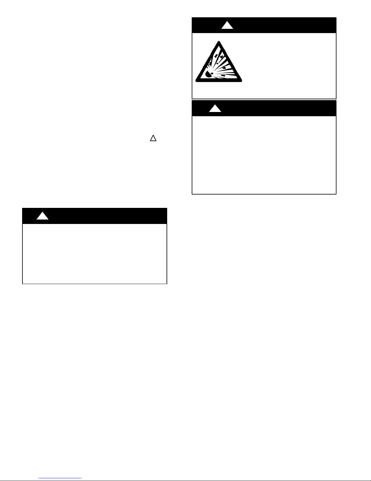
!WARNING
ELECTRICAL SHOCK HAZARD
Failure to follow this warning could result in personal
injury or death.
Before installing, modifying, or servicing system, main
electrical disconnect switch must be in the OFF
position. There may be more than 1 disconnect switch.
Lock out and tag switch with a suitable warning label.
EXPLOSION HAZARD
Failure to follow this warning could
result in death, serious personal injury,
and/or property damage.
Never use air or gases containing
oxygen for leak testing or operating
refrigerant compressors. Pressurized
mixtures of air or gases containing
oxygen can lead to an explosion.
!WARNING
CAUTION
!
EQUIPMENT DAMAGE HAZARD
Failure to follow this caution may result in equipment
damage or improper operation.
Do not bury more than 36 in. (914 mm) of refrigerant pipe
in the ground. If any section of pipe is buried, there must be
a 6 in. (152 mm) vertical rise to the valve connections on
the outdoor units. If more than the recommended length is
buried, refrigerant may migrate to the cooler buried section
during extended periods of system shutdown. This causes
refrigerant slugging and could possibly damage the
compressor at start−up.

328 014525201 3
Specifications subject to change without notice.
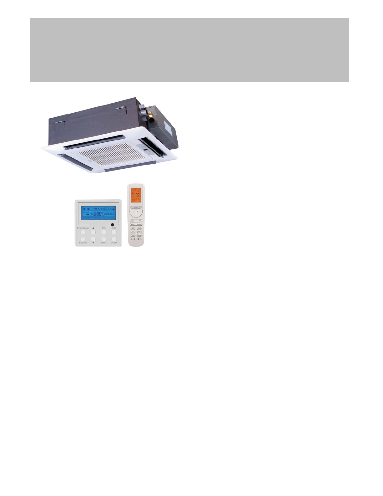
PARTS LIST
Wired Remote Controller Remote Controller
Fig. 1 - Parts List
NOTE: If the outdoor unit is higher than the indoor unit, prevent rain from flowing into the indoor unit along the connection pipe by making a
downward arc in the connection pipe before it enters the wall to the indoor unit. This ensures that rain drips from the connection pipe before it enters
the wall.
−Piping and the interconnecting wiring are field supplied.
−The illustration above is only a sketch. Different models may be slightly different.
Table 1— Parts List Indoor Cassette
Indoor Cassette
Size Name Qty
12,18
Remote control 1
Battery (1.5V) 2
Screw M4X25 2
GasketM6Xφ18X1.4 4
GasketM10Xφ30X2.5 10
Screw ST4.8X13 HC 4
Screw M6X25 4
Nut of Connector Pipe(B) Package 1
Pipe Connection Nut ("I" shape) 1
Drain Hose 1
Connection wire of wired control 1
Wired controller 1
24
Remote control 1
Battery (1.5V) 2
Screw M4X25 2
Gasket location board 1
GasketM10Xφ30X2.5 10
Screw ST4.8X13 HC 4
bellows φ16 1
Nut of Connector Pipe(B) Package 1
Drain Hose Sub-Assy 1
Connection wire of wired control 1
Wired controller 1
The following units are covered in these installation instructions.
Table 2—Indoor Units
Description kBTUh V-Ph-Hz Indoor Model Number Grille Model Number
Cassette
12 208/230-1-60 DLFBHC12K1A DLFBHC01K1A
18 208/230-1-60 DLFBHC18K1A DLFBHC01K1A
24 208/230-1-60 DLFBHC24K1A DLFBHC02K1A

4328 014525201
Specifications subject to change without notice.
SYSTEM REQUIREMENTS
Allow sufficient space for airflow and servicing unit. See Fig. 4 for minimum required distances between unit and walls or ceilings.
Piping
IMPORTANT: Both refrigerant lines must be insulated separately.
STable 3 lists the pipe sizes for the indoor unit. Refer to the outdoor unit installation instructions for other allowed piping lengths and refrigerant
information.
Table 3—Indoor Unit Pipe Sizes
UNIT SIZE 12K
(208/230V)
18K
(208/230V)
24K
(208/230V)
Gas Pipe in 3/8 1/2 5/8
(mm) 9.52 12.7 16
Liquid Pipe in 1/4 1/4 3/8
(mm) 6.35 6.35 9.52
Wiring
All wires must be sized per NEC (National Electrical Code) or CEC
(Canadian Electrical Code) and local codes. Use the Electrical Data
table MCA (minimum circuit amps) and MOCP (maximum over
current protection) to correctly size the wires and the disconnect fuse or
breakers respectively.
Per caution note, only stranded copper conductors with a 600 volt
rating and double insulated copper wire must be used. The use of BX
cable is not recommended.
Recommended Connection Method for Power and Communication
Wiring −Power and Communication Wiring:
The main power is supplied to the outdoor unit. The field supplied 14/3
power/communication wiring from the outdoor unit to the indoor unit
consists of four (4) wires and provides the power for the indoor unit.
Two wires are high voltage AC power, one is communication wiring
and the other is a ground wire.
Recommended Connection Method for Power and Communication
Wiring (To minimize communication wiring interference) Power
Wiring:
The main power is supplied to the outdoor unit. The field supplied
power wiring from the outdoor unit to the indoor unit consists of three
(3) wires and provides the power for the indoor unit. Two wires are
high voltage AC power and one is a ground wire.
To minimize voltage drop, the factory recommended wire size is 14/2
stranded with a ground.
Communication Wiring:
A separate shielded stranded copper conductor only, with a 600 volt
rating and double insulated copper wire, must be used as the
communication wire from the outdoor unit to the indoor unit. Please
use a separate shielded 16GA stranded control wire.
CAUTION
!
EQUIPMENT DAMAGE HAZARD
Failure to follow this caution may result in equipment
damage or improper operation.
SWires should be sized based on NEC and local codes.
SUse copper conductors only with a 600 volt rating and
double insulated copper wire.
328 014525201 5
Specifications subject to change without notice.
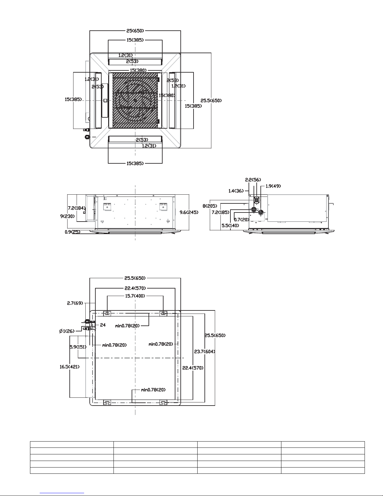
DIMENSIONS −INDOOR
Fig. 2 - Size 12 and 18 Cassette Dimensions
Table 4—Dimensions Indoor
SYSTEM SIZE 12 18
Height (H) in (cm) 9.1 (23.1) 9.1 (23.1)
Width (W) in (cm) 22.4 (56.9) 22.4 (56.9)
Depth (D) in (cm) 22.4 (56.9) 22.4 (56.9)
Weight-Net lbs(kgs) 39.7 (18) 39.7 (18)
This manual suits for next models
4
Table of contents
Other HEIL Air Conditioner manuals


Popular Air Conditioner manuals by other brands

Fujitsu
Fujitsu ASYG 09 LLCA installation manual

York
York HVHC 07-12DS Installation & owner's manual

Carrier
Carrier Fan Coil 42B Installation, operation and maintenance manual

intensity
intensity IDUFCI60KC-3 installation manual

Frigidaire
Frigidaire FAC064K7A2 Factory parts catalog

Sanyo
Sanyo KS2432 instruction manual


Mitsubishi Electric
Mitsubishi Electric PUHZ-RP50VHA4 Service manual

Panasonic
Panasonic CS-S18HKQ Service manual

Panasonic
Panasonic CS-E15NKE3 operating instructions

Gree
Gree GWH18TC-K3DNA1B/I Service manual

Friedrich
Friedrich ZoneAire Compact P08SA owner's manual

Daikin
Daikin R32 Split Series installation manual