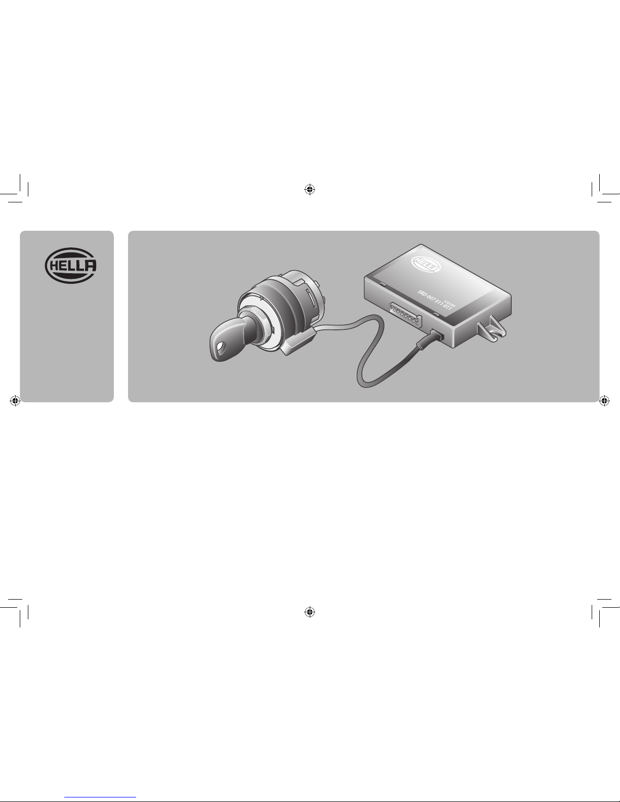
Hella 5RD 007 511-011 User manual
MONTAGEANLEITUNG
WEGFAHRSPERRE 12V /24V
INSTALLATION INSTRUCTIONS
ELECTRONIC IMMOBILIZER 12V /24V
INSTRUCTION DE MONTAGE
DISPOSITIF D’IMMOBILISATION 12 V/24 V
MONTERINGSBESKRIVNING
STARTSPÄRR 12 V /24 V
MONTAGEHANDLEIDING
STARTONDERBREKER 12V / 24V
INSTRUCCIONES DE MONTAJE
INMOVILIZADOR ANTIRROBO 12V / 24V
ISTRUZIONI DI MONTAGGIO
IMMOBILIZER 12V /24V
ASENNUSOHJE
AJONESTO 12/24 V
MONTAGEANLEITUNG
WEGFAHRSPERRE 12V /24V
INSTALLATION INSTRUCTIONS
ELECTRONIC IMMOBILIZER 12V /24V
INSTRUCTION DE MONTAGE
DISPOSI TIF D’IMM OBILISATI ON 12 V/24 V
MONTERINGSBESKRIVNING
STARTSPÄRR 12 V /24 V
MONTAGEHANDLEIDING
STARTONDERBREKER 12V / 24V
INSTRUCCIONES DE MONTAJE
INMOVILIZADOR ANTIRROBO 12V / 24V
ISTRUZIONI DI MONTAGGIO
IMMOBILIZER 12V /24V
ASENNUSOHJE
AJONESTO 12/24 V
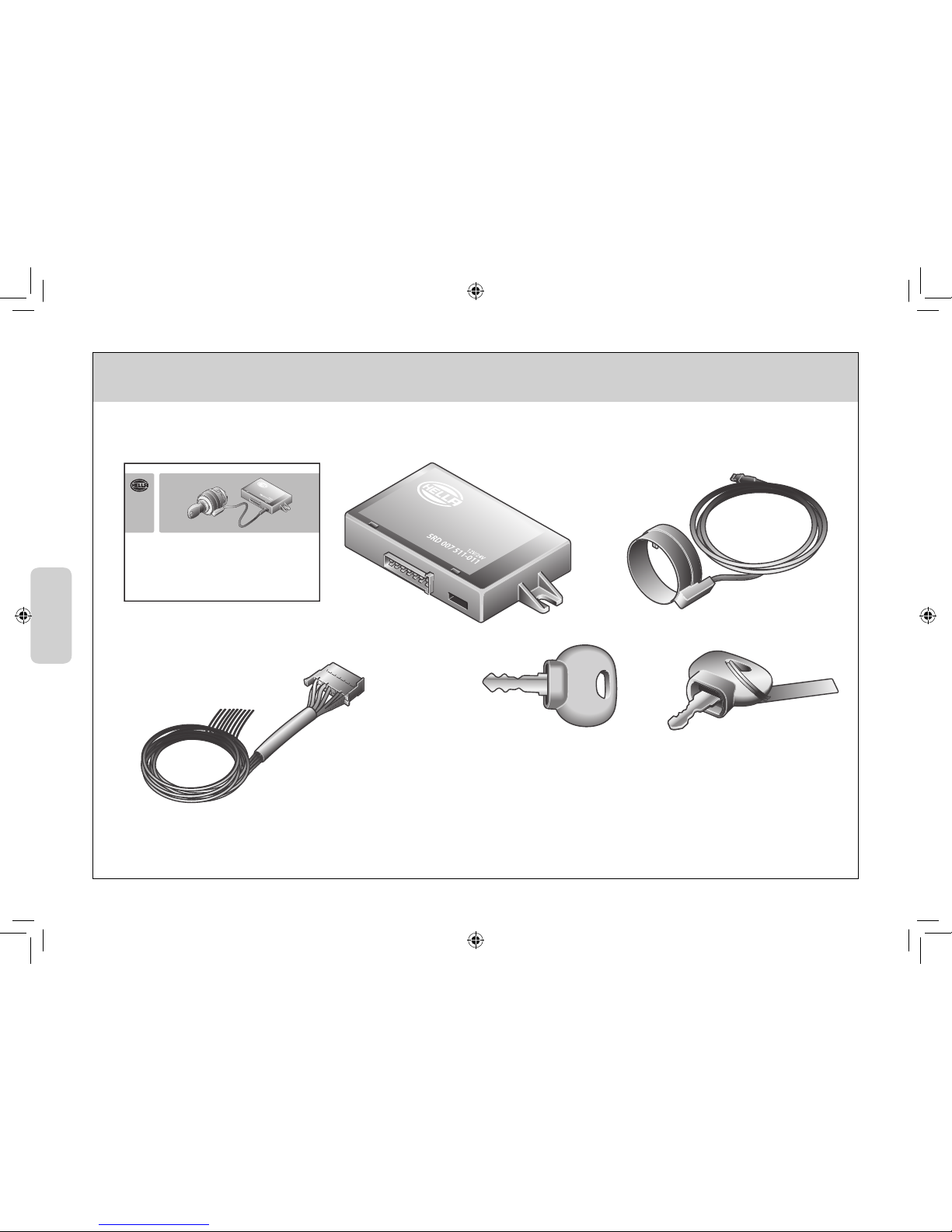
Lieferumfang
Scope of delivery
Fourniture
Leveransomfattning
Leveringsomvang
Alcance de suministro
Contenuto della confezione
Toimituksen sisältö
2
5RD 007 511-011
1x 1x 1x
1x
2x
rot
red
rouge
röd
rood
rajo
rosso
punainen
blau
blue
bleu
blå
blauw
azul
blu
sininen
1x
3A
KL.31(-)
(+) KL.15
( < 15 A)
( < 15 A)
( < 15 A)
KL.50
KL.50
KL.30(-)
3A
14 12 10 8 6 4 2
13 11 9 7 351
1
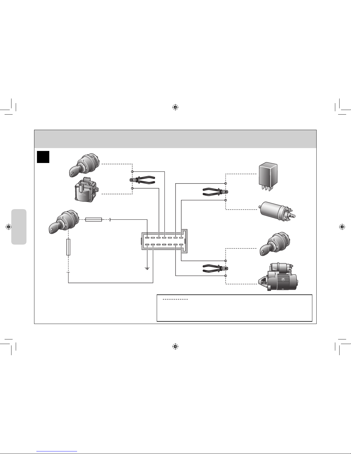
3
Fahrzeugseitige Leitung
On-board cabling
Conduite côté véhicule
Ledning på fordon
Kabel aan zijde van voertuig
Cable del vehículo
Cavo lato veicolo
Ajoneuvon puoleinen johto
Esempio di installazione
Asennusesimerkki
Installationsbeispiel
Sample installation
Exemple d’installation
Installationsexempel
Installatievoorbeeld
Ejemplo de instalación
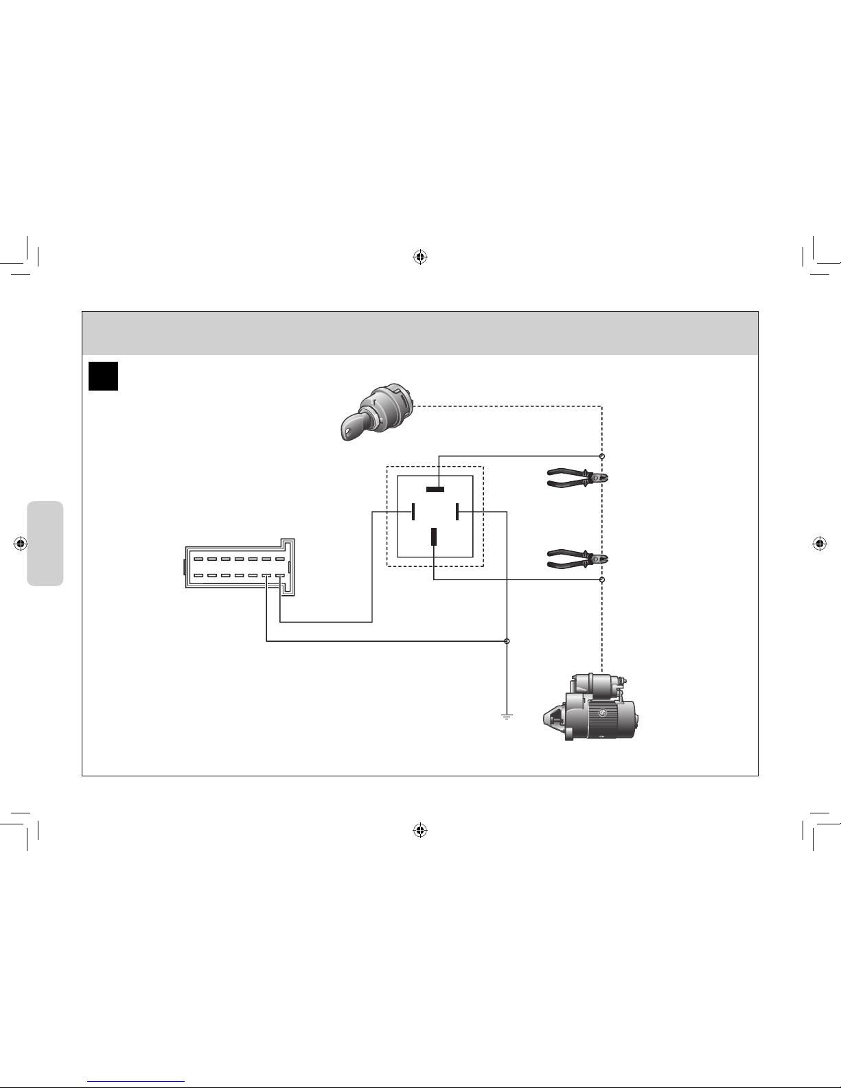
( > 15 A)
87
86
30
85
KL.50 (+)
KL.50
KL.31(-)
14 12 10 8 6 4 2
13 11 9 7 351
2
4
Esempio di installazione
Asennusesimerkki
Installationsbeispiel
Sample installation
Exemple d’installation
Installationsexempel
Installatievoorbeeld
Ejemplo de instalación
5
DEUTSCH Technische Änderungen vorbehalten 7-14
DE
ITALIANO Con riserva di modifiche tecniche 55-62
IT
SVENSKA Vi reserverar oss för tekniska ändringar 31-38
SV
ENGLISH Subject to alteration without notice 15-22
EN
SUOMI Oikeus teknisiin muutoksiin pidätetään 63-70
FI
NEDERLANDS Technische wijzigingen voorbehouden 39-46
NL
FRANÇAIS Sous réserve de modifications techniques 23-30
FR
ESPAÑOL Reservadas modificaciones técnicas 47-54
ES
6
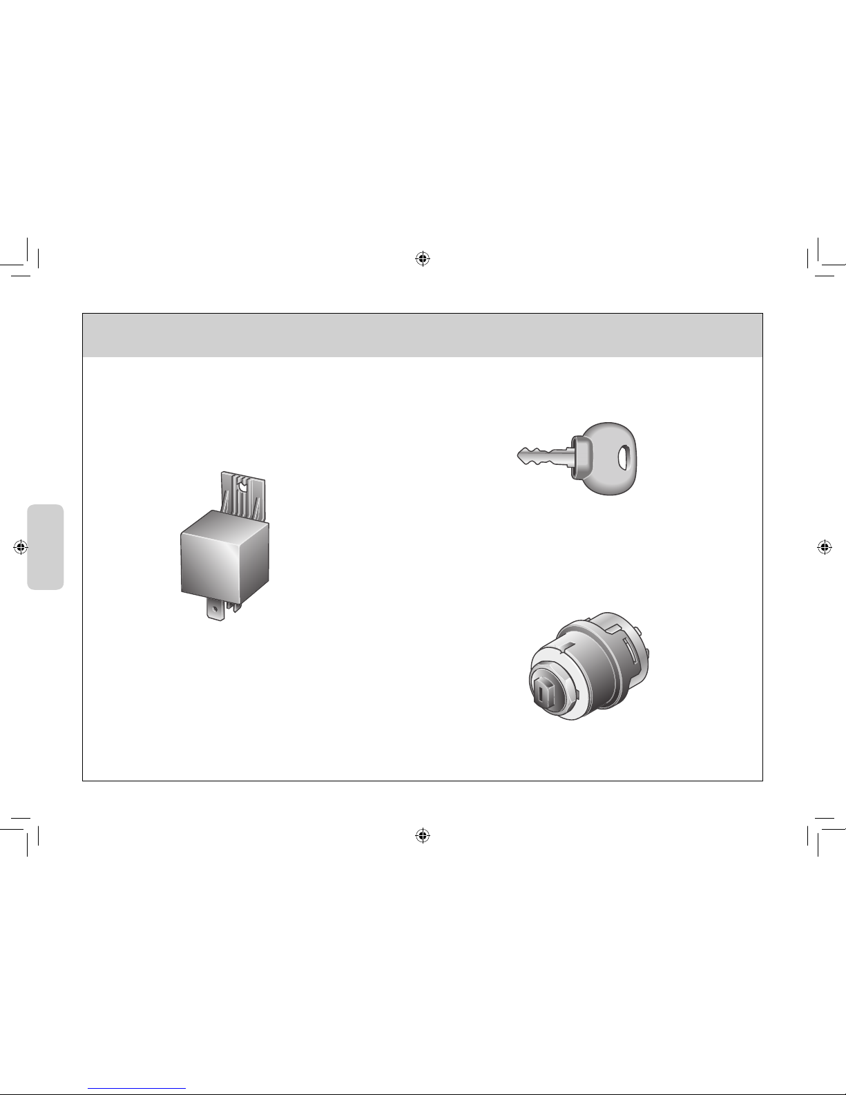
Accessori
Lisätarvikkeet
Zubehör
Accessories
Accessories
Tillbehör
Toebehoren
Accessorios
6JB 003 959-0XX
9SL 194 565-001
4RA 003 437-081 / 12V
Leistungsrelais
4RA 003 437-091 / 24V
7
DEUTSCH
DE
Montagehinweise
Wichtig: Lesen Sie die Montageanleitung vor der Installation vollständig und beachten Sie folgende Hinweise.
• Die Wegfahrsperre ist entsprechend der Montageanleitung einzubauen.
• Bedingt durch den Eingriff in betriebsrelevante Funktionen des Fahrzeuges sollte die Anlage nur durch geschultes Fachpersonal
installiert werden.
• Montieren Sie das Modul aus Gründen des Manipulationsschutzes an einem versteckten Einbauort.
• Stellen Sie sicher, dass nachgerüstete Verbindungen nicht als solche zu erkennen sind.
• Entfernen Sie vor dem Anschluss der Kabel die Farbringe um Manipulationen zu verhindern.
• Der Gewährleistungsanspruch entfällt wenn das Siegeletikett des Steuergerätes beschädigt wird.
Steuergerät
Das Steuergerät verdeckt, nicht sichtbar, schwer zugänglich, z.B. hinter dem Armaturenbrett, montieren. Für die Montage 2 Schrauben
verwenden. Das Modul unter Ausnutzung der Kabellängen mit nach unten zeigenden Anschlüssen (Feuchtigkeitsschutz !) montieren.
Kabelanschluss
Klemmen Sie vor der Installation den Minuspol der Batterie ab.
Elektrische Verkabelung gemäß Schaltplan durchführen. 1Seite 3.
Um eine langfristige Stromversorgung zu gewährleisten sollten für die Kabelverbindungen keine Einschneidverbinder verwendet werden.
Der jeweilige Leitungsverbinder ist entsprechend dem Leitungsquerschnitt auszuwählen. Die Spannungs-versorgungsleitungen des
Steuergerätes sind jeweils mit 3A Sicherungen (nicht im Lieferumfang) abzusichern.
Im Steuergerät stehen 3 Relais mit Schliesserfunktion zur Verfügung, mit denen betriebsrelevante Funktionen, z.B. die Ansteuerung des
Starters, der Zündanlage oder der Krastoffpumpe unterbrochen werden können. Ist die Stromaufnahme der jeweiligen Komponente
> 15A ist zusätzlich ein Leistungsrelais (nicht im Lieferumfang) einzubauen. 2Seite 4.
ACHTUNG!
Bei Arbeiten am Fahrzeug, die zu Überspannungen im Bordnetz führen (z.B. Schweißarbeiten an Rahmen und Fahrwerk), muss das
Steuergerät vom Bordnetz getrennt werden. (z.B. Steckverbinder lösen, Sicherung entfernen, Batterie abklemmen).

8
DEUTSCH
DE
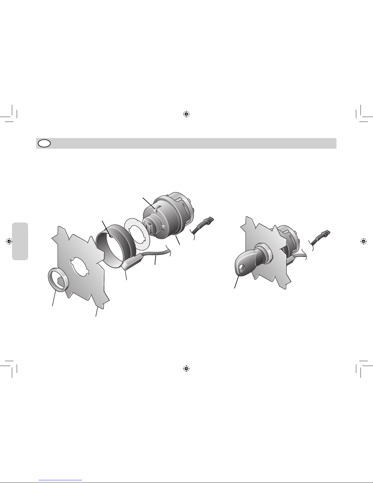
Armaturenbrett
Schlüssel
Kabel
Führungssti
Aussparung
Antennenkörper
Startschalter
Mutter
Antenneneinheit
Antenne unterhalb Armaturenbrettes befestigen.
Das Antennenkabel darf nicht gekürzt oder anderweitig verändert werden. Bei Schlüsselkompatiblen Zündschlössern anderer Hersteller ohne
Aussparung für die Antennenführung, entfernen Sie den Führungssti vorsichtig aus dem Antennenring.

KL.30 11
1
3
KL.15 14
KL.31 13
2
4
8
10
14 12 10 8 6 4 2
13 11 9 7 351
1234
Relais 1
Relais 2
Relais 3
9
DEUTSCH
DE
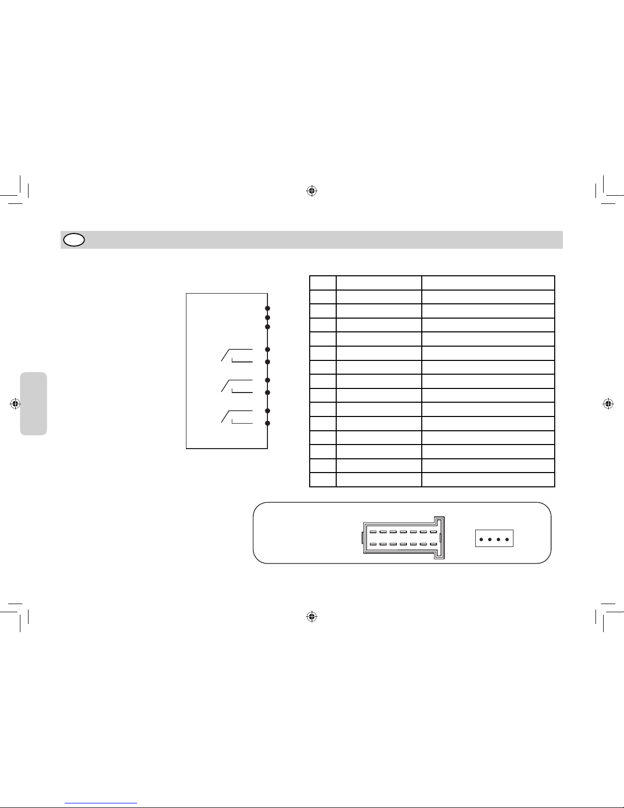
Elektrischer Anschluss
Pin Farbe Kabelenden Belegung
1 Blau Relais 1 Eingang
2 Gelb Relais 2 Eingang
3 Lila Relais 1 Ausgang
4 Grün Relais 2 Ausgang
5 Nicht belegt
6 Nicht belegt
7 Nicht belegt
8 Braun Relais 3 Eingang
9 Nicht belegt
10 Rot Relais 3 Ausgang
11 Weiβ Versorgungspannung Kl.30
12 Nicht belegt
13 Schwarz Masse Kl.31
14 Gelb-Grün Versorgungspannung Kl.15
Blockschaltbild
Steckkontakt 1
Steuergerät
Pinbelegung:
Steckkontakt
für Antenne

10
DEUTSCH
DE
Systembeschreibung
Steuergerät:
Das System besteht aus einem mechanischem Schließsystem und einer unabhängig funktionierenden elektronisch codierten Wegfahrsperre.
Das mechanische System ist ein Startschalter (nicht im Lieferumfang) der Fa. Hella. Dieser schaltet mit einem mechanisch codierten Schlüs-
sel die Klemme15. Bei eingeschalteter Klemme 15 ist der Schlüssel mechanisch arretiert und kann nicht herausgezogen werden.
Die elektronisch codierte Wegfahrsperre trennt bei Aktivierung mindestens 3 betriebsrelevante Steuereinheiten, wie zum Beispiel, den
Starter, die Krastoffpumpe und die Zündung. Die Trennung erfolgt potenzialfrei über die im Steuergerät integrierten Relais.
Elektronischer Schlüssel
Der elektronische Schlüssel basiert auf berührungsloser Transpondertechnik. Der Transponder besitzt eine eigene, batterielose Versorgung
und ist in dem mechanischen Schlüssel des Startschalters fest integriert.
Aktivierung der Wegfahrsperre
Die Wegfahrsperre ist selbstaktivierend, d.h. ohne zusätzliches Einschalten oder abweichende Handhabungen. Wenn der mechanische Schlüssel
im Startschalter in Position ‘0’ (Klemme15 aus), ist die Wegfahrsperre generell aktiviert. Wird der Schlüssel des Startschalters von einer
Position in die Position ‘0’ gebracht, wird die Wegfahrsperre nach 5s automatisch aktiviert. Die Wegfahrsperre wird und bleibt auch aktiviert,
wenn der Schlüssel in Position ‘0’ stecken bleibt.
Die Aktivierung der Wegfahrsperre erfolgt durch das Trennen von mindestens 3 betriebsrelevanten Steuereinheiten, z.B. den Starter, die
Zündung und die Krastoffpumpe.
Deaktivierung der Wegfahrsperre
Die Deaktivierung der Wegfahrsperre erfolgt, wenn ein gültiger mechanischer Schlüssel und ein gültiger elektronischer Schlüssel (Trans-
ponder) vorhanden ist. Das Lesen des Transponders erfolgt erst, wenn der mechanische Schlüssel im Startschalter die Klemme 15 einge-
schalten hat. Dadurch besteht die Notwendigkeit, erst das mechanische Schließsystem zu öffnen, bevor der elektronische Schlüssel geprü
wird. Eine Manipulation der Wegfahrsperre bei abgeschalteter Zündung ist dadurch nicht möglich.
Die Deaktivierung der Wegfahrsperre erfolgt durch das Schliessen von mindestens 3 betriebsrelevanten Steuereinheiten, z.B. den Starter,
die Zündung oder die Krastoffpumpe.
11
DEUTSCH
DE
Anlernen neuer Schlüssel
Das Anlernen für neue Schlüssel erfolgt durch einen Masterschlüssel, der durch einen roten Schlüsselknauf gekennzeichnet ist. Dieser Mas-
terschlüssel muss sorgfältig aufbewahrt werden und er ist nur für den Wegfahrsperrensatz zu verwenden, mit dem er zusammengeliefert ist.
Das heiβt, die Nummer auf dem Anhänger des roten Schlüssels muss mit der Nummer auf dem Steuergerät übereinstimmen.
Anlernvorgang der blauen Schlüssel:
Wichtiger Hinweis:
Der Anlernvorgang muss innerhalb 20 Sek. abgeschlossen werden.
a) Masterschlüssel ins Zündschloss einstecken und in Position 1 (Zündung an) schalten.
b) 5 Sekunden warten. Schlüssel abziehen.
c) Blauen Schlüssel ins Zündschloss einstecken und in Position 1 schalten.
d) 1-2 Sekunden warten. Schlüssel abziehen.
e) Der Schlüssel ist nun angelernt.
Für das Anlernen mehrerer Schlüssel können die Schlüssel hintereinander in das Zündschloss gesteckt werden. Die einzelnen Schlüssel müs-
sen dabei ca.1 Sekunde in der Position „1“ bleiben, wobei zu beachten ist, dass zwischen 2 anzulernenden Schlüsseln nicht mehr als 4 Sek.
Verweilen darf. Auf diese Weise können bis zu 10 Schlüssel angelernt werden.
Hinweis: Wird der Masterschlüssel länger als 20 Sek. bei „Zündung an“ im Zündschloss gelassen ,werden alle bereits angelernten Schlüssel
gelöscht.
Löschen angelernter Schlüssel im Steuergerät
Das Löschen von angelernten Schlüsseln ist notwendig, wenn ein angelernter Schlüssel verloren gegangen ist. Bei dem Löschvorgang werden
alle angelernten Schlüssel gelöscht. Nach dem Löschen können alle vorhandenen Schlüssel neu angelernt werden.
Die Löschprozedur erfolgt durch Einstecken des Masterschlüssels in das Zündschloss und das Betätigen der Position ‘1’ (Klemme 15 ein) für
min. 20 Sekunden. Danach sind alle angelernten Schlüssel gelöscht und es können alle vorhandenen Schlüssel neu angelernt werden.
Der Code des Masterschlüssels wird bei dem Löschvorgang nicht gelöscht.
Der rote Masterschlüssel kann nicht für den Betrieb des Fahrzeugs verwendet werden und dient lediglich zum Anlernen der Blauen
Schlüssel.

12
DEUTSCH
DE
Sicherheitsfunktionen
Werden innerhalb 1 minute mehr als 5 Schlüssel im Zündschloss betätigt mit verschiedenen ungültigen Codes, bleibt die Wegfahrsperre für
15 Minuten aktiviert und akzeptiert in dieser Zeit keine gültigen Schlüssel. Dieses Verfahren verhindert das ‘Probieren’ von verschiedenen
Schlüsseln und das zufällige Finden des richtigen Schlüssels.
Werden verschiedene ungültige Schlüssel erkannt, ohne dass das Zündschloss in die Position ‘0’ gebracht wurde, bleibt die Wegfahrsperre für
15 Minuten aktiviert und akzeptiert keine gültigen Schlüssel. Das Akzeptieren von gültigen Schlüsseln erfolgt erst nach den 15 Minuten und
dem Erkennen der Position ‘0’ des Startschalters. Dadurch wird verhindert, dass Schlüssel getestet werden, ohne das mechanische Zünd-
schloss zu betätigen, z.B. wenn das Zündschloss gewaltsam in Stellung ‘1’ gebracht wurde.
Manipulationssicherheit
Eine Unterbrechung der Versorgungsleitung oder anderer Steuerleitungen führt nicht zu einer Deaktivierung der Wegfahrsperre oder zum
Löschen von Daten (z.B. Datencodes). Alle relevanten Daten werden in einem nichtflüchtigen Speicher gespeichert.
Periodische Unterbrechungen der Versorgungsleitung oder anderer Steuerleitungen führen nicht zu einer Deaktivierung der Wegfahrsperre
oder zum Löschen von Daten.
Ein Absenken der Versorgungsspannung innerhalb von 10s auf Werte bis 0V und anschliessendes Erhöhen auf Betriebsspannung führt nicht
zum Deaktivieren der Wegfahrsperre.
Leitungsgeführte Störimpulse nach DIN und ISO führen nicht zum Deaktivieren der Wegfahrsperre.
Magnetische Felder führen nicht zum Deaktivieren der Wegfahrsperre.
Eine dauerhae Deaktivierung über Diagnose- oder Steuerleitungen (Override) ist nicht möglich.
Entwickelt unter Berücksichtigung der Hella Qualitätsmaßnahmen (QM).Es besteht keine Konformität mit ASIL-Standards.
Bei der Integration des Produkts ist die Einhaltung in Betracht kommender ASIL-Anforderungen zu beachten.

13
DEUTSCH
DE
Störungsursachen
Wegfahrsperre hat keine Funktion:
- Spannungsversorgung an Steckkontakten überprüfen
- Antennensteckverbindung prüfen
- Antennenkabel prüfen (siehe ‘Prüfung Antenne’)
- Schlüssel mit angelerntem Transponder verwenden
Anlernen von Schlüssel nicht möglich:
- Kl. 30 an Steuergerät nicht angeschlossen
- vorher keinen oder falschen Masterschlüssel benutzt (roter Griff)
- Zeit für Masterschlüssel im Zündschloss zu kurz oder zu lang
- anzulernender Schlüssel ist ohne Transponder
- Antenne defekt (siehe ‘Prüfung Antenne’)
- Anlernzeit für Schlüssel im Zündschloss zu kurz
Löschen von angelernten Schlüssel nicht möglich:
- keinen oder falschen Masterschlüssel benutzt (roter Griff)
- Zeit für Masterschlüssel im Zündschloss zu kurz
- Antenne defekt (siehe ‘Prüfung Antenne’)
Prüfung der Antenne
- Antennenkabel auf Brüche oder Knickstellen prüfen
- Antennenstecker auf fehlerhae Kontakte prüfen
Messen der Antennenparameter:
- Antennenstecker aus Steuergerät abstecken
- Widerstandsmessung am Antennenstecker Pin1 und Pin2
- Widerstand von 1 Meter Antennenkabel und Antenne muss ca.7,5Ω betragen.
14
DEUTSCH
DE
Technische Daten
Steuergerät
Elektrische Daten:
Spannungsbereich: 6 - 32V
Nennspannung: 24V und 12V
Temperaturbereich: -40°C bis +85°C
Stromaufnahme Relais offen: typ. 50mA / 24V DC
Stromaufnahme Relais geschlossen: typ. 300mA / 24V DC
Stand-by Strom (Kl.30 Betrieb): ≤ 30μA / 24V DC
Relaisausgänge:
max. Schaltspannung: 27V
Spannungsabfall (10A): typ. 50mV
Max. 300mV
Min. Schaltstrom: 1A / 5V DC
max. Schaltstrom: 15A
Dauerstrom (Tu 23°C) 10A
RF-Modul:
Übertragungsfrequenz: typ.134,2 kHz
Kodierungsverfahren: FSK
Reichweite: ca. 10cm
Mechanische Daten:
Lagertemperatur: 2h / +95°C
Betriebstemperatur: -40°C bis +85°C
Schutzart: auf Anfrage
Einbaulage: beliebig
Material Gehäuse: PA66
15
ENGLISH
EN
Assembly information
Important: Read these instructions attentively right through before carrying out the installation, and take note of the following hints.
• The immobilizer must be installed in accordance with the instructions.
• The installation process involves actions that may affect the vehicle’s operational functions, and should therefore be carried out only
by trained specialist staff.
• To prevent the possibility of tampering, mount the unit at a concealed location.
• Make sure that retrofitted connections cannot be recognised as such.
• To prevent tampering, remove the colored rings prior to connecting up the cables.
• Any damage to the seal attached to the control unit will void the warranty.
Control unit
Mount the control unit in a concealed location, where it is out of sight and not easy to get at, e.g. behind the dashboard. Use two screws to
attach the unit. Make use of the spare cable to mount the unit with its connections pointing downwards (to protect it from moisture).
Connecting the cables
Before installing the unit, disconnect the minus pole of the battery.
Connect up the electrical wiring as shown in the circuit diagram 1page 3.
For a durable power supply connection, do not use self-cutting cable connections. Select a suitable connector for the cross-section of the
cable. All power cables to the control unit should be fitted with 3A fuses (not supplied).
The control unit provides three relay contacters that can be used to interrupt operational functions, such as activating the starter, the
ignition system or the fuel pump. If the chosen component draws more than 15A, you will also need to install a power relay (not supplied)
2page 4.
ATTENTION!
If you need to carry out any work on the vehicle that might overload the on-board power network (e.g. welding the chassis or frame) you
should first disconnect the control unit from the on-board supply (e.g. unplug connectors, take out the fuse, disconnect the battery).
16
ENGLISH
EN
Dashboard
Keys
Cable
Guide pin
Recess
Aerial body
Start switch
Nut
Aerial unit
Attach the aerial underneath the dashboard.
The aerial cable must not be shortened or otherwise modified. In the case of other manufacturers’ key-compatible ignition switches that have
no recess for the passage of the aerial cable, carefully remove the guide pin from the aerial ring.
KL.30 11
1
3
KL.15 14
KL.31 13
2
4
8
10
14 12 10 8 6 4 2
13 11 9 7 351
1234
Relay 1
Relay 2
Relay 3
17
ENGLISH
EN
Electrical connection
Pin Color of cable ends Assignment
1 Blue Relay 1 input
2 Amber Relay 2 input
3 Purple Relay 1 output
4 Green Relay 2 output
5 Not assigned
6 Not assigned
7 Not assigned
8 Brown Relay 3 input
9 Not assigned
10 Red Relay 3 output
11 White Mains voltage terminal 30
12 Not assigned
13 Black Ground terminal 31
14 Yellow-green Mains voltage terminal 15
Block diagram
Plug contact 1
Control unit
Pin assignment:
Plug contact
for aerial
18
ENGLISH
EN
System description
Control unit:
The system consists of a mechanical locking system and an independently functioning electronically encoded immobilizer. The mechanical
system is a starter switch manufactured by Hella (not included). This uses a mechanically coded key to switch terminal 15. When terminal 15
is activated, the key is mechanically locked and cannot be withdrawn.
When activated, the electronically encoded immobilizer disconnects at least three operational control units, such as the starter, the fuel pump
and the ignition. The disconnection is effected potential-free via the relays integrated into the control unit.
Electronic key
The electronic key makes use of contact-free transponder technology. The transponder has its own battery-free power supply and is perma-
nently integrated into the mechanical starter switch.
Activating the immobilizer
The immobilizer is self-activating, i.e. without any no additional switches or extraneous maneuvres. It will generally be active whenever the
mechanical key is in position ‘0’ of the start switch (terminal 15 is off). If the key of the start switch is turned from some other position to posi-
tion ‘0’, the immobilizer will be activated automatically aer a period of 5 seconds. The immobilizer is also activated, and remains activated,
if the key is le in position ‘0’.
The immobilizer activates by disconnecting at least three operational control units, such as the starter, the ignition and the fuel pump.
Deactivating the immobilizer
The immobilizer is deactivated when a valid mechanical key and a valid electronic key (transponder) are both present. The transponder is not
addressed until the mechanical key in the start switch has switched on terminal 15. This means that is necessary to first open the mechanical
locking system before the electronic key is checked. This means that it is not possible to tamper with the immobilizer while the ignition is
turned off.
The immobilizer is deactivated by connecting at least three operational control units, such as the starter, the ignition or the fuel pump.

19
ENGLISH
EN
Training new keys
Training for new keys makes use of a master key, which has a red knob. This master key must be kept in a safe place and may be used only
for the immobilizer with which it was supplied. This means that the number on the tag of the red key must agree with the number on the
control unit.
Training procedure for blue keys:
Important note:
The training process must be completed within 20 seconds.
a) Insert the master key in the ignition and switch to position 1 (ignition on).
b) Wait 5 seconds and then withdraw the key.
c) Insert a blue key into the ignition and switch to position 1 (ignition on).
d) Wait 1-2 seconds and then withdraw the key.
e) The key is now trained.
You can train a number of keys by inserting them into the ignition one aer another. When doing this, each of them must remain in position 1
for about 1 second, taking care that no more than 4 seconds elapses between training two consecutive keys. Up to 10 keys can be trained in
this way.
Note: If the master key is le in the ignition in the “on” position for longer than 20 seconds, all the previously trained keys will be cleared.
Clearing trained keys from the control unit
You will need to clear the trained keys if one of them has been lost. The procedure clears all the trained keys. When this has been done, the
remaining keys can be retrained.
The procedure for clearing keys is to insert the master key in the ignition and switch it to position 1 (terminal 15 is on) for a period of at least
20 seconds. Aer this time, all the trained keys will have been cleared and the available keys can then be retrained.
This procedure does not clear the code of the master key.
The red master key cannot be used to operate the vehicle. It serves only for training blue keys.
20
ENGLISH
EN
Safety functions
If more than five keys with invalid codes are inserted in the ignition within one minute, the immobilizer will be activate for a period of 15
minutes, and during this time will not accept any valid keys. This prevents anybody from ‘trying out’ different keys and happening on the right
one.
If different invalid keys are detected without the ignition being switched to position ‘0’, the immobilizer will be activate for a period of 15 minutes,
and during this time will not accept any valid keys. Valid keys will be accepted only aer waiting the 15 minutes when the device detects that
the start switch has been turned to position ‘0’. This prevents keys from being tested without activating the mechanical lock, for instance by
forcibly turning the ignition switch to position ‘1’.
Tamper protection
Interrupting the power supply or any other control lines does not deactivate the immobilizer or clear any data (e.g. codes). All the relevant
data is stored in non-volatile memory.
Periodic interruptions of the power supply or any other control lines do not deactivate the immobilizer or clear any data.
Reducing the supply voltage to values down to and including 0V over a period of 10 seconds and then taking it back up to the operating voltage
does not deactivate the immobilizer.
Conducted transients as defined by DIN and ISO do not deactivate the immobilizer.
Magnetic fields do not deactivate the immobilizer.
It is not possible to use diagnostic or control lines to permanently deactivate the immobilizer (override).
Developed in due consideration of the Hella quality measures (QM). There is no conformity with the ASIL standards.
In the event of product integration, compliance with the relevant ASIL requirements is to be observed.
Table of contents
Languages:
Popular Car Alarm manuals by other brands


Ultra Start
Ultra Start 650 Series owner's manual

Audiovox
Audiovox Prestige Platinum+ APS-511C owner's manual

Sparkrite
Sparkrite SRA8 Guide

Federal Signal Corporation
Federal Signal Corporation Pathfinder Siren Series Installation and maintenance manual

Falcon
Falcon Predator XL3 Installer manual

Audiovox
Audiovox Auto Security XR91 Programming guide


