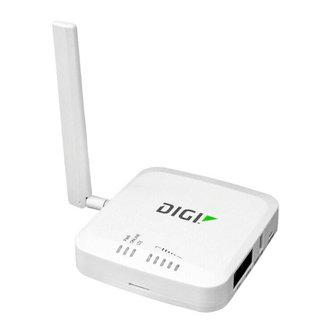
HelloDevice Super Series User manual

1
HelloDevice Super Series
SS100
User Guide
Version 1.0
2002-08-01

2
User Guide for the HelloDevice SS100
Version 1.0
Firmware version 1.0.0
Last revised on August 12002
Printed in Korea
Copyright
Copyright 2002, Sena Technologies, Inc. All rights reserved.
Sena Technologies reserves the right to make changes and improvements to its product without
providing notice.
Trademark
HelloDevice™is a trademark of Sena Technologies, Inc.
Windows®is a registered trademark of Microsoft Corporation.
Ethernet® is a registered trademark of XEROX Corporation.
Notice to Users
When a system failure may cause serious consequences, protecting life and property against such
consequences with a backup system or safety device is essential. The user agrees that protection
against consequences resulting from system failure is the user's responsibility.
This device is not approved for life-support or medical systems.
Changes or modifications to this device not explicitly approved by Sena Technologies will void the
user's authority to operate this device.
Technical Support
Sena Technologies, Inc.
210 Yangjae-dong, Seocho-gu
Seoul 137-130, Korea
Tel: (+82-2) 573-5422
Fax: (+82-2) 573-7710
E-Mail: [email protected]
Website: http://www.sena.com

3
Revision history
Date Part number Description
June 2002 Pre-release of manual.
Aug 1 2002 Initial release of manual.

4
Contents
1: Introduction 7
1.1 Overview ..............................................................................................................................7
1.2 Package Check List ..............................................................................................................8
1.3 Product Specification ............................................................................................................9
1.4 Terminologies and acronyms ..............................................................................................10
2: Getting Started 12
2.1 Panel Layout ......................................................................................................................12
2.2 Connecting the Hardware ...................................................................................................14
2.2.1 Connecting to the network ........................................................................................14
2.2.2 Connecting to the device ...........................................................................................14
2.2.3 Connecting the power ...............................................................................................15
2.3.1 Using Serial console .................................................................................................17
2.3.2 Using Remote console ..............................................................................................19
3: IP Address Configuration 22
3.1 Static IP ..............................................................................................................................22
3.1.1Overview ..................................................................................................................22
3.1.2 IP address ................................................................................................................23
3.1.3 Subnet mask .............................................................................................................23
3.1.4 Default gateway ........................................................................................................23
3.1.4 Primary and Secondary DNS ....................................................................................24
3.2 DHCP .................................................................................................................................24
3.2.1Overview ..................................................................................................................24
3.2.2 DHCPsetting ............................................................................................................25
3.3 PPPoE ...............................................................................................................................26
3.3.1Overview ..................................................................................................................26
3.3.2 PPPoE setting ..........................................................................................................26
4: Serial Port Configuration 28
4.1 Host mode configuration .....................................................................................................30
4.1.1Overview ..................................................................................................................30
4.1.2 TCP server mode operations ....................................................................................32
4.1.3 TCP client mode operations ......................................................................................34
4.1.4 TCP server/client mode operations ...........................................................................37
4.1.5 UDP tunneling mode operations ................................................................................39
4.1.6 UDP server mode operations....................................................................................40
4.1.7 Modem emulation mode operations ..........................................................................41
4.2 UART configuration ............................................................................................................43

5
4.2.1Type .........................................................................................................................44
4.2.2 Baud rate ..................................................................................................................44
4.2.3 Data bits, Stop bits, Parity .........................................................................................45
4.2.4 Flow control ..............................................................................................................46
4.2.5 DTR/DSR behavior ...................................................................................................46
4.3 Cryptography configuration .................................................................................................47
4.3.1 SSL Cryptography Method ........................................................................................47
4.3.2 Root and server certificates display ...........................................................................49
4.3.2 Root and server certificates upload ...........................................................................51
4.3.3 Cipher method selection ...........................................................................................53
4.4 Options ...............................................................................................................................54
4.4.1 Inactivity timeout .......................................................................................................54
4.4.2 Inter-character timeout ..............................................................................................54
5: Advanced Options Configurations 56
5.1 Remote host access control ................................................................................................56
5.1.1 Configuration access ................................................................................................57
5.1.2 Serial Port access .....................................................................................................58
5.2 Manual DNS configuration ..................................................................................................58
5.3 Locating server ...................................................................................................................59
5.3.1Overview ..................................................................................................................59
5.3.2 Locating server configuration ....................................................................................59
5.3.3 Locating server communication protocol ...................................................................60
5.4 Dynamic DNS Configuration ...............................................................................................61
5.4.1Overview ..................................................................................................................61
5.4.2 Dynamic DNS configuration ......................................................................................61
6: System Status and Log 63
6.1 Display system status .........................................................................................................63
6.2 Display log data ..................................................................................................................64
6.3 Automatic log delivery by email ...........................................................................................64
7: System administration 66
7.1 User name and password ...................................................................................................66
7.2 Date and time configuration ................................................................................................67
8: System tools 70
8.1 Factory default reset ...........................................................................................................70
8.2 Firmware upgrade ..............................................................................................................70
8.3 Ping test .............................................................................................................................72
9: SNMP Configurations 73
9.1 MIB-II System objects Configuration ...................................................................................73

6
9.2 Access Control Configuration ..............................................................................................74
9.3 Trap Receiver Configuration ...............................................................................................75
9.4 Management using SNMP ..................................................................................................76
10: Management through the Web Browser interface 78
10.1 Overview ..........................................................................................................................78
10.2 Firmware upgrade using Web browser interface ................................................................81
AppendixA: Connections 86
A.1 Ethernet Pin outs ................................................................................................................86
A.2 Serial Port Pin Outs ............................................................................................................86
A.3 Ethernet Wiring Diagram ....................................................................................................87
A.4 Serial Wiring Diagram ........................................................................................................87
Appendix B: Well-known port numbers 89
Appendix C: Troubleshooting 90
C.1 Power/LED status troubleshooting ......................................................................................90
C.2 Serial console troubleshooting ...........................................................................................90
C.3 Remote console troubleshooting ........................................................................................90
C.4 IP address troubleshooting .................................................................................................91
C.5 DHCP troubleshooting .......................................................................................................91
C.6 TCP server operation troubleshooting ................................................................................91
C.7 Serial communication troubleshooting ................................................................................92

7
1: Introduction
1.1 Overview
The HelloDevice Super Series allows you to network-enable a variety of serial devices that were not
originally designed to be networked. This capability brings the advantages of remote management and
data accessibility to thousands of serial devices over the network.
The SS100 is a versatile serial-Ethernet communication device. The SS100 supports variety of the
serial communication types such as RS232, RS422 or RS485 allowing virtually any asynchronous
serial device to be accessed over a network.
As for the Internet connectivity, the SS100 supports open network protocols such as TCP/IP, UDP and
PPPoE (PPP-over-Ethernet) allowing serial devices to be accessed over DSL-based broadband
network orconventional LAN (Local Area Network) environment through the 10/100 Mbps (10Base-T,
100Base-TX) ethernet interface.
The SS100 provides the full-featured management functions such as status monitor, remote reset,
error log monitor and firmware upgrade using Telnet, serial console port or Web browser under the
password protection support. In addition, the SS100 provides IP address filtering function to protect
unintentional data streams to be transmitted to the serial device, and public key cryptography based
SSL data encryption to promise secure data communication. The SS100 also has the SNMP(Simple
Network Management Protocol) agent supporting SNMP v1 and v2 protocols, and Dynamic DNS client
for updatinguser’shostname account offered by various service provider.
The SS100 was designed to accommodate the unique requirements of the Retail POS, Security,
Automation and Medical marketplaces.
Parts of this manual assume the knowledge on concepts of the Internetworking protocols and serial
communications. If you are not familiar with these concepts, please refer to the standards or the
documentation on each subject.

8
1.2 Package Check List
-SS100 external box
-110V or 230V Power supply adapter
-Serial console/data cable
-A hardcopy of Quick Start Guide
-CD-ROM including the HelloDevice Manager and User Guide

9
1.3Product Specification
One male DB9 serial port for data communication or console
Serial speeds 1200bps to 230Kbps
Flow Control:
Hardware RTS/CTS, Software Xon/Xoff
Serial Interface
Signals:
RS232 Rx, Tx, RTS, CTS, DTR, DSR, GND
RS422 Rx+, Rx-,Tx+,Tx-
RS485 Data+, Data-
10 Base-T/100Base Ethernet with RJ45 Ethernet connector
Network InterfacesSupports static and dynamic IP address
Protocols ARP, IP/ICMP
TCP, UDP
Telnet,
DNS, Dynamic DNS,
SMTP, HTTP
DHCP client
PPPoE, SNMP
NTP
User ID & Password
Data encryption: SSL
Security
IP address filtering
Telnet, Serial Console, Web interface, SNMP or HelloDevice Manager
System log and statistics
Error log storage up to 100 messages(12KB)
Automatic email delivery of error log
Full-featured system status display
Management
Firmware
Stored in Flash memory
Downloadable via serial console, telnet or http
Diagnostic LED Power
Ready
Serial Rx/Tx for serial port
10/100 Base, Link, Act for LAN port
Supply voltage
5.0 VDC
Power
Supply current
400 mA (nom.)
Environmental Operating temperature: 0 ~ 55oC
Storage temperature: -4 ~ 66 oC
Dimension
100 mm L (3.94 in.)
72 mm W (2.83 in.)
25 mm H (0.98 in.)
Physical
properties
Weight
240g
Approvals FCC(A), CE(A), MIC
Warranty 5-year limited warranty

10
1.4 Terminologies and acronyms
The Internetworking related terminologies used frequently in this manual are defined clearly to help
your better understanding of the SS100.
MAC address
On a local area network or other network, the MAC (Media Access Control) address is the computer's
unique hardware number. (On anEthernet LAN, it's the same as your Ethernet address.)
It is a unique 12-digit hardware number, which is composed of 6-digit OUI (Organization Unique
Identifier) number and 6-digit hardware identifier number. The SS100 has the MAC address of 00-01-
95-xx-xx-xx, which is labeled on the bottom side of the external box.
Host
A user’s computer connected to the network
In Internet protocol specifications, the term "host" means any computer that has full two-way access to
other computers on the Internet. A host has a specific "local or host number" that, together with the
network number, forms its unique IP address.
Session
Aseries of interactions between two communication end points that occur during the span of a single
connection
Typically, one end point requests a connection with another specified end point and if that end point
replies agreeing to the connection, the end points take turns exchanging commands and data ("talking
to each other"). The session begins when the connection is established at both ends and terminates
when the connection is ended.
Client/Server
Client/server describes the relationship between two computer programs in which one program, the
client, makes a service request from another program, the server, which fulfills the request.
A server is a computer program that provides services to other computer programs in the same or
other computers, whereas a client is the requesting program or user in a client/server relationship. For
example, the user of a Web browser is effectively making client requests for pages from servers all
over the Web. The browser itself is a client in its relationship with the computer that is getting and
returning the requested HTML file. The computer handling the request and sending back the HTML file
is a server.

11
Table 1-1Acronym Table
ISP Internet Service Provider
PC Personal Computer
NIC Network Interface Card
MAC Media Access Control
LAN Local Area Network
UTP Unshielded TwistedPair
ADSL Asymmetric Digital Subscriber Line
ARP Address Resolution Protocol
IP Internet Protocol
ICMP Internet Control Message Protocol
UDP User Datagram Protocol
TCP Transmission Control Protocol
DHCP Dynamic Host Configuration Protocol
SMTP Simple MailTransfer Protocol
FTP File Transfer Protocol
PPP Point-To-Point Protocol
PPPoE Point-To-Point Protocol over Ethernet
HTTP HyperText Transfer Protocol
DNS Domain Name Service
SNMP Simple Network Management Protocol
UART Universal Asynchronous Receiver/Transmitter
Bps Bits per second (baud rate)
DCE Data Communications Equipment
DTE Data Terminal Equipment
CTS Clear to Send
DSR Data Set Ready
DTR Data Terminal Ready
RTS RequestTo Send

12
2: Getting Started
This chapter describes how toset up and configure the SS100in the first place.
-2.1 PanelLayoutexplains the panel layout and LED indicators.
-2.2 Connecting the Hardware describes how to connect the power, the network, and the serial
device to the SS100.
-2.3 Accessing Console Portdescribes how to access the console port using a serial console ata
local site or telnet console at a remotesite.
Following items are pre-required to get started.
-One DC power adapter (included in the package).
-One RS-232 serial cable for configuration or connecting the RS-232 serial device
(included in the package).
-One PC with Network Interface Card (hereafter, NIC) and/or one RS232 serial port.
-Terminal emulation program running on the PC
-One Ethernet cable
2.1 Panel Layout
The SS100 has six LED indicator lamps for status display. Uppermost lamp indicates the system
power-on status. Next lamp indicates the system running status. Third lamp indicates status of receive
and transmit of the serial port for data communication. Next three lamps indicate 100 Base-T Ethernet
connection, 10/100 Base Ethernet Link and Ethernet Activity, respectively.
Table 2-1. LED indicator lamps
Lamps Function
Power Turned on to RED if power is suppliedStatus Ready Turned on to YELLOW if system is ready to run or running.
Blinking when an error is occurred. (Check the log to identify the source of
error. The log display is discussed on Section 6.2)
Serial port Rx/Tx Blink whenever there is any incoming or outgoing data stream through the
serial port of the SS100
100Base Turned on to GREEN if connected to 100 Base Ethernet network
Link Turned on to GREEN if connected to 10 or 100 Base Ethernet network
Ethernet
Act Blink whenever there is any activities such as incoming or outgoing packets
through the SS100 Ethernet port

13
Figure 2-1. The panel layout of the SS100

14
2.2 Connecting the Hardware
This section describes how to connect the SS100 to serial device for the first time test.
-Connect the Ethernet cable between the SS100 and Ethernet hub or switch
-Connect the serial cable between the SS100 and a serial device
-Connectthe power to the SS100
2.2.1 Connecting to the network
Connect the one end of the Ethernet cable to the SS100 10/100Base-T port and the other to the
Ethernet network.
Figure 2-3. Connecting anetwork cable to the SS100
2.2.2 Connecting to the device
Connect the serial data cable between the SS100 and the serial device. And push the Data/Console
switchto the Data side. If necessary, supply the power to the serial device attached to the SS100.
Note:
If the configuration of the SS100 through the serial console is required, connect the serial cable to the
serial port of user’s computer first. And push the Data/Console switch to the Console side.
Configuration of the SS100 is discussed on Section 2.3.

15
Figure 2-4. Connectinga serial device to the SS100
2.2.3 Connecting the power
Connect the power jack to the SS100 power jack using DC power adapter included in the package. If
the power is properly supplied, the [Power] lamp of the SS100 will maintain solid red.
Figure2-2. Connecting the power to the SS100
If the Ethernet cable is properly hooked up, the SS100 will have a valid connection to the Ethernet
network by indicating:
-[100BASE] lamp of the SS100 maintains solid green if connected network is 100 Base-T
-[LINK] lamp of the SS100 maintains solid green

16
-[ACT] lamp continuously blinks to indicate the incoming/outgoing Ethernet packets
If any of the above does not happen, the SS100 is not properly connected to the Ethernet network.
If [READY] lamp is turned on to YELLOW, then the SS100 is ready for use.

17
2.3. Accessing Console Port
There are two ways to access console port of the SS100 depending on whether the user is located at
a local site or a remote site.
-Serial console:
Local userscan connect directly to the serial console port on the rear side of the SS100 using
serial console cable (null-modem cable).
Note that Data/Console switchmust be pushed to the Console side.
-Remote console:
Remote userscan make a telnet connection to the remote console port (port 23) of the SS100via
TCP/IP network.
Both methods require the user to log into theSS100 in order tocontinue.
Note:
Configuration based on web browser interface is discussed in chapter 10 Management through the
Web Browser Interface.
2.3.1 Using Serial console
1) Connect the one end of the serial cable to the serial port on the SS100.
Figure 2-5. Connecting a serial cable to the SS100

18
2) Push the Data/Consoleswitch to the Console side.
3) Connect the other end of the cable to the serial port of user’s computer.
4) Run a terminal emulator program such as HyperTerminal. Set up the serial configuration
parameters of the terminal emulation program as follows:
9600 Baud rate, Data bits 8, Parity None, Stop bits 1, No flow control
5) Press [ENTER] key.
6) Type the user name and password to log into the SS100. A factory default setting of the user
name and password are both admin.
Welcome to SS-100 Configuration
-------------------------------------------------------------------------------
Console#1 (Serial) : Not Connected [THIS]
Console#2 (Telnet) : Available
Console#3 (Telnet) : Available
Console#4 (Telnet) : Available
-------------------------------------------------------------------------------
Press Enter
Login : admin
Password : *****
7) If the user logged into the SS100 successfully, the main menu screen will appear on the
computer.
From the main menu screen, shown below in Figure 2-6,users can select the menu item for the
configuration of the SS100 parameters by typing the menu number and pressing [ENTER] key. In the
submenu screen, users can configure the required parameters guided by online comments. All the
parameters are stored into the non-volatile memory space of the SS100, and it will not be stored until
users select menu 8.Save changes. All the configuration change will be effective after selecting
the menu 9. Exit and apply changes or 0. Exit and reboot.
-------------------------------------------------------------------------------
Welcome to SS-100 configuration page
Current time : 2002/06/02 23:02:15 F/W REV. : v1.0.0
Serial No. : SS100-020300069 MAC Address : 00-01-95-04-13-45
IP mode : DHCP IP Address : 192.168.1.254
-------------------------------------------------------------------------------
Console#1 (Serial) : Connected [THIS]
Console#2 (Telnet) : Available
Console#3 (Telnet) : Available
Console#4 (Telnet) : Available
-------------------------------------------------------------------------------
Select menu
1. IP configuration
2. Serial port configuration
3. SNMP configuration
4. System Status & log
5. System administration

19
6. Advanced options
7. System tools
8. Save changes
9. Exit and apply changes
0. Exit and reboot
<ESC> Back, <ENTER> Refresh
----->
Figure 2-6.The SS100 main menu screen
2.3.2 Using Remote console
The static IP address of the SS100 must be assigned before userscan access the remote console
port (See IP Address Configuration in chapter 3 for details). Remote console access function is
optional, and can be disabled in the remote access option on the menu. This is useful when users
don't want others to modify the existing configuration (See Remote Host Access Control in section
5.1 for details). Up to three users can log into the remote console port of the SS100 simultaneously.
When multiple remote consoles are opened, first opened console has a right to change parameter
values while the others have right only to read parameter values. If the serial console is opened first,
all of the remote telnet consoles do not have a right to update parameter values. If the serial console is
opened after one of remote consoles is opened, serial console do not have a right to update
parameter values until the remote console having read/write permission is closed. The port number for
the remote console is 23, which is a TCP port number assigned for Telnet.
Note:
Abnormal closing of remote telnet console which has read/write permission may block another
opening of telnet or serial console which want to have read/write permission for a while. After 3
minutes from the abnormal closing, SS100 will close that abnormally closed connection.
1) Run a telnet program or a program that supports telnet functionssuch as TeraTerm-Pro or
HyperTerminal. The target IP address and the port number should be those of the SS100. If
required, specify the port number as 23. Type the following command in the command line
interface of your computer.
telnet 192.168.1.254
Or run a telnet program with parameters as follows.

20
Figure 2-7 Telnet program set up example
2) The user has to log into the SS100. Type the user name and password. A factory default
setting of the user name and password are both admin.
Welcome to SS-100 Configuration
-------------------------------------------------------------------------------
Console#1 (Serial) : Not Connected
Console#2 (Telnet) : Available
Console#3 (Telnet) : Available
Console#4 (Telnet) : Available
-------------------------------------------------------------------------------
Press Enter
Login : admin
Password : *****
Figure 2-8. Users’logging into the SS100
3) If the user logged into the SS100 successfully, the same main menu screen as the one of
serial console will be displayed. The user can select the menu by typing the menu number
and then pressing [ENTER] key. In the corresponding menu screen, the user can configure
the required parameters.
4) If serial console or the other remote consoles are connected already, new console will be
established as read-only mode. Figure 2-10 shows the screen display of a read-only mode
console. The console number which user currently log in can be distinguished by [THIS] mark
at the end ofconsole status.
Welcome to SS-100 Configuration
-------------------------------------------------------------------------------
Console#1 (Serial) : Not Connected
Console#2 (Telnet) : Established (192.168.0.8)
Console#3 (Telnet) : Available
Console#4 (Telnet) : Available
-------------------------------------------------------------------------------
Press Enter
This manual suits for next models
1
Table of contents
Popular Server manuals by other brands

Gigabyte
Gigabyte G221-Z30 user manual
Bodet Time
Bodet Time Time Server Netsilon 9 user manual

Lenovo
Lenovo ThinkServer TD100x user guide

HP
HP 4410t - Mobile Thin Client Administrator's reference guide
GlobalScale
GlobalScale GuruPlug Server Standard quick start guide

Gigabyte
Gigabyte GS-SR101 System installation guide
