HENNING BOTTLE ROCKET User manual

!
!
!
!
!
!
TUBE GUITAR AMPLIFIER
MODEL: BOTTLE ROCKET
OWNER’S MANUAL

WELCOME TO HENNING AMPLIFICATION
Congratulations and thank you for choosing the Henning Bottle Rocket Guitar Amplifier!
At Henning Amplification, our mission is to design and build the finest tube guitar amplifiers for discerning
tone freaks. Hand built in the USA using the highest quality components and materials, our amplifiers sound
killer, look cool and are as durable and road ready as anything currently on the market.
The Bottle Rocket is one of the most versatile single channel amplifier you can buy today. It is a 50 watt
tube amp featuring dual gain controls (each with a 3-way bright switch), dual foot switchable masters (each
with a 3-way saturation switch) and and an overall master to provide great tones from bedroom to concert
levels.
The Bottle Rocket’s preamp design is loosely based on the flagship Cherry Bomb’s ROD channel, however
we made significant changes to make it more versatile. It is capable of heavier/more saturated tones, as
well as giving you the ability to tighten the bass response considerably. The keys to the Bottle Rocket’s
versatility are the dual gain controls and their corresponding 3-way bright switches. The dual gain controls
provide you with the ability to control the amp’s gain in both the first and second preamp stages, allowing
you to shape the tone to your exact taste. The 3-way bright switches on each gain control not only affect
the high end response of the amp, but also tighten the response and add considerable perceived gain in the
left and right positions (center position is off). You can mix the bright switch settings and gain control
settings to get everything from classic rock tones to the heaviest modern metal tones. The amp also cleans
up incredibly well with your guitar’s volume, even with high output pickups, so you won’t be needing a
dedicated clean channel live.
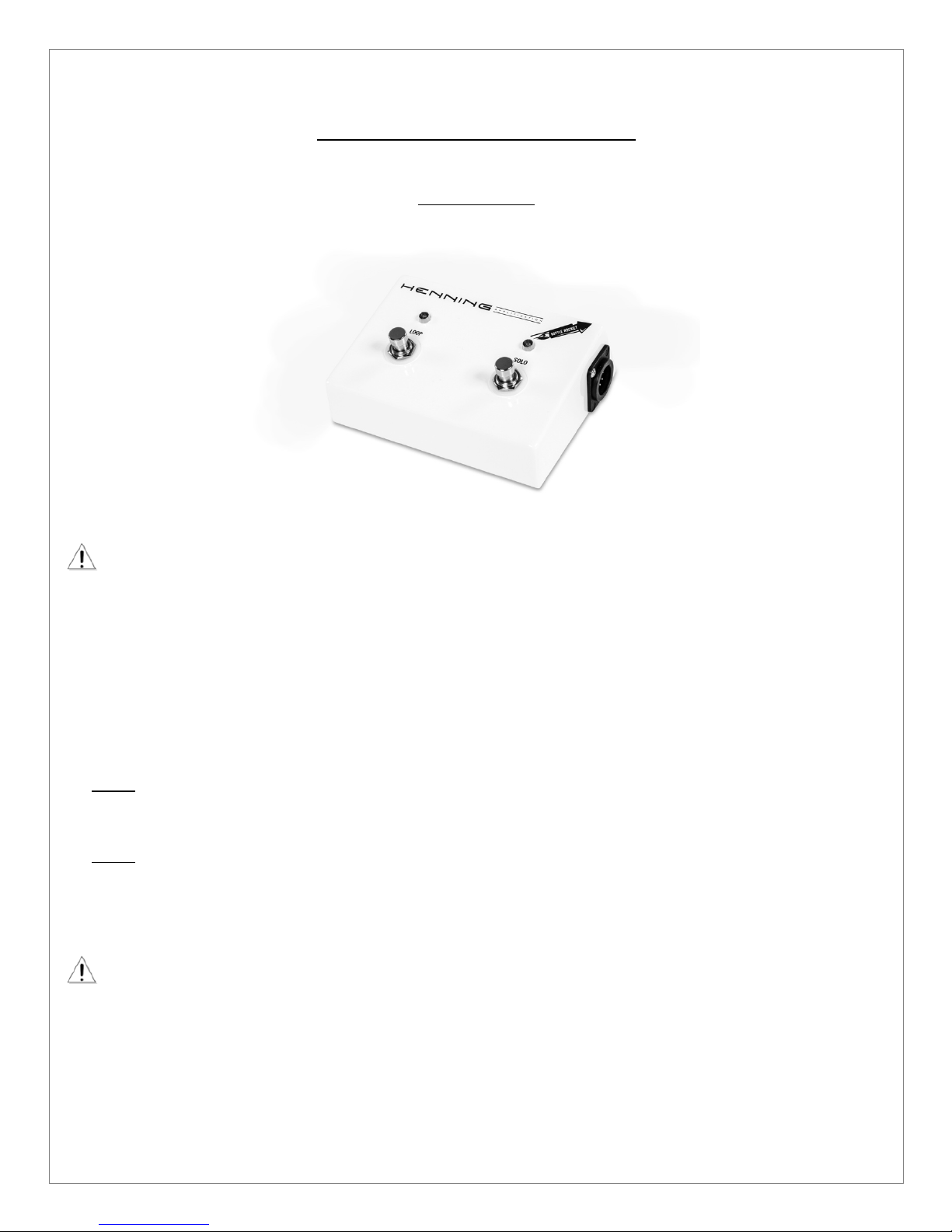
The Bottle Rocket also allows you to change the gain response of the amp with the 3-way saturation
switches associated with the main channel master (labeled VOLUME) and foot switchable solo channel
master (labeled SOLO), allowing tremendous flexibility in sculpting YOUR ultimate tone. Singing lead tones
and massive power chords can be dialed in with ease. The Bottle Rocket’s foot switchable solo channel
master and associated 3-way saturation switch can be set to provide a gain and volume boost for live
soloing.
The Bottle Rocket also features global presence and resonance controls. The presence control provides high
frequency variable feedback in the power amp section, while the resonance control adds depth to the bass
response.
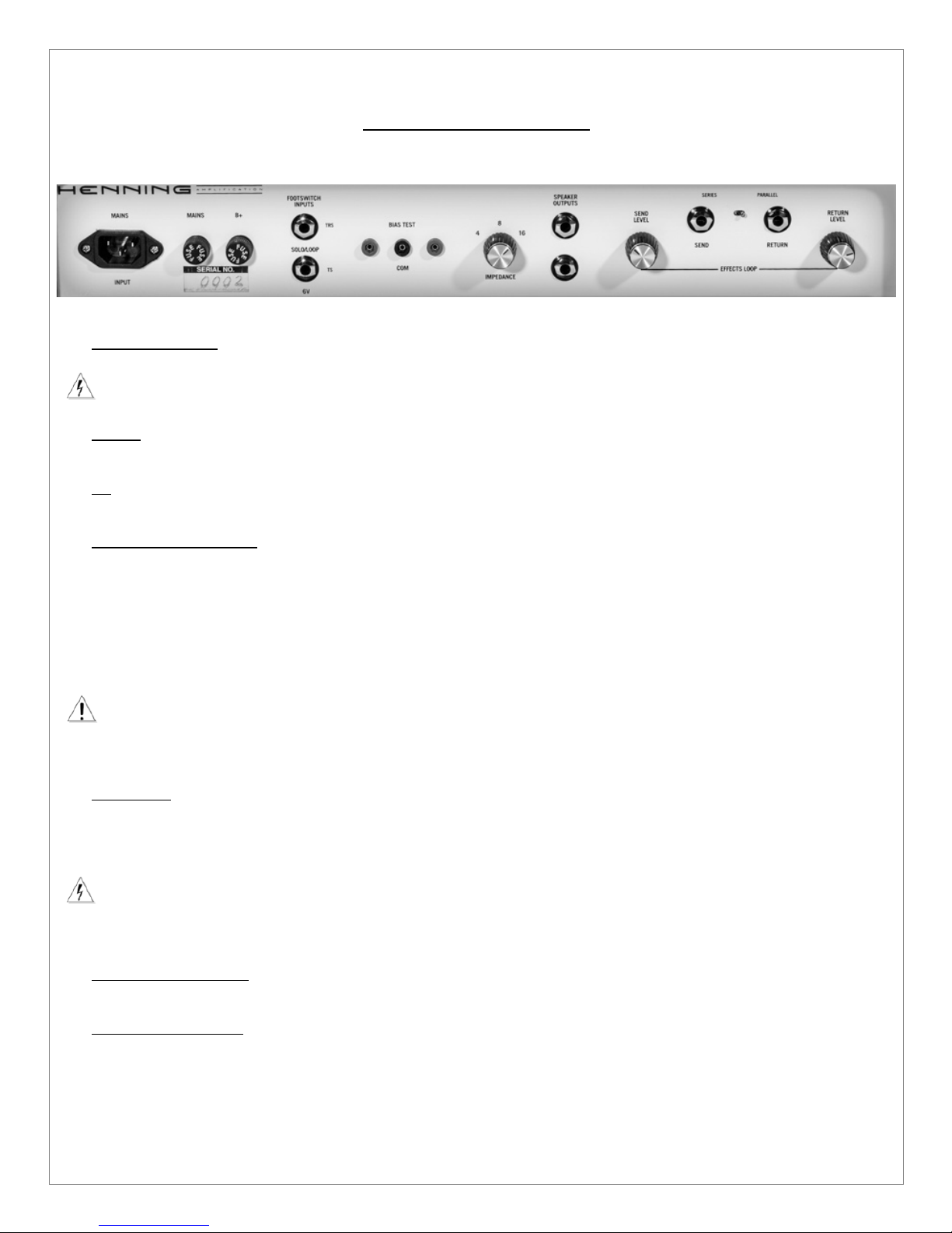
The Bottle Rocket also features the same foot switchable, tube-buffered effects loop as the Cherry Bomb so
you can add your time-based effects after the gain stages of the amp where they belong. You can choose
either series or parallel mode for the effects loop, affording you the ultimate flexibility in how you want to
use pedal or rack mount effects. This loop is extremely transparent and you won’t hear any change in your
tone when switching it in and out of the signal path.
Finally, the amp also features another, overall master volume. We’re going to get a little techie on you here,
but bear with us, because this is one of the coolest features of the Bottle Rocket. This master volume is
actually a post-phase inverter master volume (PPIMV) design. We feel that this design provides the best
tones you can get for lower volume playing. You’ll get great tones with this master all the way down to
bedroom volumes. Crank the channel or solo master up and turn the overall master down to the volume
level you’d like to play at and you’ll see that the overall master also adds some perceived gain and
compression to the tone. Experiment with balancing different settings of the channel masters and overall
master to get the tone you’d like at the right volume for the room you’re playing in. Of course, cranking the
overall master up full takes it completely out of the circuit and you can just adjust the channel master/solo
master to the appropriate volume.
While the amp has a lot of options and controls, getting familiar with the Bottle Rocket amplifier is easy, so
don’t be terribly surprised that you find yourself up and running in no time. It’s really easy to dial in great
tones in both channels and find your voice with it.

IMPORTANT SAFETY INSTRUCTIONS
This symbol warns the user of dangerous voltage levels localized within the enclosure.
This symbol advises the user to read all accompanying literature for safe operation of the
unit.
Read, retain, and follow all instructions. Heed all warnings.
Only connect the power supply cord to an earth grounded AC receptacle in accordance with the voltage and
frequency rating that you specified when ordering the amp.
WARNING: To prevent damage, fire or shock hazard, do not expose this unit to rain or moisture.
Unplug the power supply cord before cleaning the unit exterior (use a damp cloth only). Wait until the unit
is completely dry before reconnecting it to power.
Maintain at least 6 inches (15.25 cm) of unobstructed air space behind the unit to allow for proper
ventilation and cooling of the unit.
This product should be located away from heat sources such as radiators, heat registers, or other products
that produce heat.
This product may be equipped with a polarized plug or a grounding type plug. A polarized plug has two
blades with one wider than the other. A grounding type plug has two blades and a third grounding prong.
The wide blade or the third prong is provided for your safety. This is a safety feature. If you are unable to
insert the plug into the outlet, contact an electrician to replace your obsolete outlet. Do not defeat the
safety purpose of this plug.
Protect the power supply cord from being pinched or abraded.
This product should only be used with a cart or stand that is recommended by the manufacturer.
The power supply cord of this product should be unplugged from the outlet when left unused for a long
period of time, or during electrical storms.
This product should be serviced by qualified service personnel when: the power supply cord or the plug has
been damaged; or objects have fallen, or liquid has been spilled onto the product; or the product has been
exposed to rain; or the product does not appear to operate normally or exhibits a marked change in
performance; or the product has been dropped, or the enclosure damaged.
Do not drip or splash liquids, nor place liquid filled containers on the unit.
CAUTION: There are no user serviceable parts inside, refer servicing to qualified personnel only.
Henning Amplification amplifiers and loudspeaker systems are capable of producing very high sound
pressure levels, which may cause temporary or permanent hearing damage. Use care when setting and
adjusting volume levels during use.
Hazardous voltages may be present within the cabinet even when the power switch is off and the power
cord is connected. Therefore, disconnect the power cord from the rear panel power inlet before servicing.
The power inlet must remain readily operable.

BOTTLE ROCKET FUNCTIONS
FRONT PANEL, LEFT TO RIGHT
1. GUITAR INPUT – Plug your guitar, pedalboard or stomp box in here
2. BRIGHT – This bright switch sets the value of the bright cap for the first gain stage of the preamp,
which can increase the high end response, tighten the amp’s response and add considerable perceived
gain. It is a 3-way switch and the center position is OFF, meaning no additional high end, tightness or
perceived gain. If the switch is set to the left position, the highest value bright cap is in the circuit. In the
right position, a more moderate bright cap is in the circuit.
3. GAIN 1 - Sets the overdrive level of the first gain stage of the preamp.
4. BRIGHT – This bright switch sets the value of the bright cap for the second gain stage of the preamp. It
operates exactly like the first bright switch described in 2. above.
5. GAIN 2 - Sets the overdrive level of the second gain stage of the preamp.
6. BASS – Passive Low frequency equalization.
7. SOLO - The SOLO switch controls whether the SOLO channel master (and associated SATURATION
switch) or the VOLUME channel master (and associated SATURATION switch) is engaged. If the
SOLO switch is set to the RIGHT, the SOLO master (and associated SATURATION switch) is engaged
and the RED LED next to the switch will be lit. If the SOLO switch is set to the LEFT, the VOLUME
channel master (and associated SATURATION switch) is engaged and the RED LED next to the switch
will not be lit. PLEASE NOTE – when the provided footswitch is connected to the amp, the SOLO switch
is not operational – the function of the switch is controlled by the footswitch instead, including whether
the RED LED lights or not.
8. MIDDLE – Passive Mid frequency equalization.
9. TREBLE – Passive High frequency equalization.
10. SATURATION – This saturation switch sets the gain style for the channel master named VOLUME. It is
a 3-way switch and the center position is OFF, meaning no additional gain and compression is added. If
the switch is set to the RIGHT position, a subtle amount of gain and compression is added. If the switch
is set to the LEFT position, a higher level of gain and compression is added.
11. VOLUME – This is the main channel master for the amp and it works in concert with the overall master
marked MASTER. We recommend that you set the overall volume of the amp using the MASTER
control and keep the channel masters (VOLUME and SOLO) fairly high (above halfway up or 12
o’clock). Of course, you can also set MASTER all the way up and set your volumes with the channel
and solo masters, it is really up to you. If the MASTER is all the way up, it is completely out of the
circuit.

12. SATURATION – This saturation switch sets the gain style for channel master named SOLO. It is a 3-
way switch and the center position is OFF, meaning no additional gain and compression is added. If the
switch is set to the RIGHT position, a subtle amount of gain and compression is added. If the switch is
set to the LEFT position, a higher level of gain and compression is added.
13. SOLO – This is the SOLO channel master control. It is only engaged when the SOLO switch (see
SOLO – 7. above) is set to the RIGHT (or the footswitch is connected and the SOLO footswitch is
engaged) with the RED LED next to it lit. It is intended as a solo boost and overrides the regular
channel master named VOLUME when engaged. You can set the associated SATURATION switch for
a lead tone and set SOLO so that it provides a boost in volume over the VOLUME channel master. As
you read in the previous section you can use the channel masters along with MASTER to get the
overall sound you want at the volume that is appropriate for the room you are playing in. We
recommend that you set the overall volume of the amp using the MASTER control and keep the solo
and channel masters fairly high (above halfway up or 12 o’clock). Of course, you can also set the
MASTER all the way up and set your volumes with the channel and solo masters, it is really up to you.
If the MASTER is all the way up, it is completely out of the circuit.
POWER AMP RESPONSE CONTROL SECTION
14. PRESENCE – High frequency variable feedback in the power amp section.
15. LOOP – The LOOP switch controls whether the tube-buffered effects loop is engaged or not. If the
LOOP switch is set to the RIGHT, the effects loop is engaged and the BLUE LED next to the switch will
be lit. If the LOOP switch is set to the LEFT, the effects loop is out of the circuit and the BLUE LED next
to the switch will not be lit. PLEASE NOTE – when the provided footswitch is connected to the amp, the
LOOP switch is not operational – the function of the switch is controlled by the footswitch instead,
including whether the BLUE LED lights or not.
16. RESONANCE - Controls low frequency interaction between amplifier and speakers. Higher settings give
the amp more tight, low end.
17. MASTER – This master volume controls the overall output volume of the amplifier. This master volume
is a post-phase inverter master volume design (PPIMV). We feel that this design provides the best tones
you can get for lower volume playing. You’ll get great sounding tones with this master all the way down
to “bedroom volumes’. Crank the channel masters up and turn the overall master down to the volume
level you’d like to play at and you’ll see that the overall master also adds some perceived gain and
compression to the tone. Experiment with balancing different settings of the channel masters and overall
master to get the tone you’d like at the right volume for the room you’re playing in. Of course, cranking
the overall master up full takes it completely out of the circuit and you can just adjust the channel
masters to the appropriate volume.
Please note that at lower settings of MASTER, due to it’s nature as a PPIMV, the PRESENCE and
RESONANCE controls will not function.
AC POWER / STANDBY
18. STANDBY - Turns on high voltage to output section.
19. ON/OFF – Switches main AC power on or off.
20. JEWEL LIGHT – The jewel light will be lit as soon as the ON/OFF switch is turned to the ON position.

REAR PANEL, LEFT TO RIGHT
1. AC MAINS INPUT – Connect to a grounded outlet.
Use only the factory supplied cord set or a UL approved equivalent type.
2. MAINS – This holds the mains fuse, which protects the amplifier from electrical faults. Replace only with
a 4 AMP SLO BLO fuse.
3. B+ - This holds the B+ fuse, which protects the power supply and output transformer from electrical
faults. Replace only with a 1 AMP FAST BLO fuse.
4. FOOTSWITCH INPUTS – This is where the footswitch connects to your amplifier. Your amplifier came
with a special cable that has an XLR connector on one end that connects to the footswitch and 2 ¼”
phone plugs on the other end. The phone plugs are labeled and colored. When you wish to use the
footswitch, connect the stereo phone plug with the RED jacket section to the footswitch input marked
“SOLO/LOOP” underneath it, and connect the mono phone plug with the BLUE jacket to the input
marked “6V” underneath it. PLEASE NOTE – When the footswitch is connected properly, the SOLO and
LOOP switches on the front panel are rendered non-operational and the footswitch controls those
switching features.
Note that if you ever forget your footswitch at a gig, a standard Marshall two button footswitch
with a single stereo phone plug will work just fine to control the SOLO and LOOP functions.
Simply plug the footswitch stereo phone plug into the footswitch input marked “SOLO/LOOP”.
5. BIAS TEST – These are the external bias points for the amp. You connect the negative probe of your
multi-meter to the center output marked COM (it is black) and then connect the positive probe of your
multi-meter to the left or right output (they are red) to set the bias of your V5 or V6 EL34 tubes. Please
see the section on biasing your amp for more information.
Please do not attempt to bias your amp unless you have experience doing so as you can
damage your tubes or other amplifier components, voiding your warranty. It is always best to have a
qualified amp technician change your tubes and bias your amp.
6. IMPEDANCE SELECT - 4, 8 or 16 ohms. Example: Two 8 Ohm cabs = 4 Ohms, two 16 Ohm cabs = 8
Ohms.
7. SPEAKER OUTPUTS – Connect these output jacks to your speaker cabinets. Make sure the
IMPEDANCE SELECT switch is set correctly for the cabinet(s) you are connecting.

When you take the amp off STANDBY, make sure you have a speaker cabinet or other load
connected. Failure to do so could damage the output transformer and the power tubes, as well
as void your warranty! Only use a cable made for speakers - instrument and line level cables
cannot be used! The Bottle Rocket has two switchable impedance speaker outputs. Make sure
you set the IMPEDANCE SELECT switch on the amplifier so it matches the cabinet you are using
– “16” if your cabinet is 16 ohm, “8” if your cab is 8 ohm or “4” if you cab is 4 ohm. Remember if
you hook up two speaker cabinets, they must have the same impedance - both 16 ohm or both 8
ohm. Set the IMPEDANCE SELECT switch to “8” if you use two 16 ohm cabinets or set it to “4” if
two 8 ohm cabinets are used. Two cabinets connected halves the total impedance of a single
cab!
8. SEND LEVEL – Controls the level of the output signal from the EFFECTS LOOP.
9. SEND – This is the output jack for the EFFECTS LOOP.
10. SERIES/PARALLEL – This switch controls the operation of the effects loop. When set to the LEFT, the
effects loop operates in series mode. When set to the right, the loop operates in parallel mode.
11. RETURN – This is the return jack for the EFFECTS LOOP where the cable returning from the output of
your effects is connected.
12. RETURN LEVEL – In the parallel mode of the effects loop, this switch controls the level of the effected
signal vs. the dry amp signal. When the control is turned fully clockwise (all the way ON), the effects
signal is equal to the dry signal.

FOOTSWITCH FUNCTIONS
LEFT TO RIGHT
To use the footswitch, it must be connected between the footswitch and the amplifier back
panel. Your amplifier came with a special cable that has an XLR connector on one end that
connects to the footswitch and 2 ¼” phone plugs on the other end. To connect the footswitch,
align the XLR type plug properly with the foot controller’s connector and then push the plug in
until it snaps - you won’t be able to pull it out. To detach, press the release button on the plug
before pulling on it. The phone plugs on the other side of the cable are colored. When you wish
to use the footswitch, connect the stereo phone plug with the RED jacket section to the
footswitch input marked “SOLO/LOOP” underneath it, and connect the mono phone plug with
the BLUE jacket to the input marked “6V” underneath it. PLEASE NOTE – When the footswitch is
connected properly, the SOLO and LOOP switches on the front panel are rendered non-
operational and the footswitch controls those switching features.
1. LOOP - The LOOP switch controls whether the tube-buffered effects loop is engaged or not. Depress
the switch to engage the loop and light the BLUE LED above the switch. To take the effects loop out of
the circuit and turn the BLUE LED off, depress the switch again.
2. SOLO - The SOLO switch controls whether the SOLO (and associated SATURATION switch) or the
VOLUME (and associated SATURATION switch) channel master is engaged. Depress the SOLO switch
to engage the SOLO channel master (and associated SATURATION switch) and light the RED LED
above the switch. Depress the switch again and the VOLUME channel master (and associated
SATURATION switch) will be engaged and the RED LED above the switch will not be lit.
Note that if you ever forget your footswitch at a gig, a standard Marshall two button footswitch
with a single stereo phone plug will work just fine to control the SOLO and LOOP functions.
Simply plug the footswitch stereo phone plug into the footswitch input marked “SOLO/LOOP”.

TUBE FUNCTION AND LOCATION
The picture above shows the locations of each tube along with alphanumeric designations used below to describe the
tubes. Below, tubes are described by the location alphanumeric, tube type and the specific tube provided in your Bottle
Rocket amp. Feel free to experiment with other tubes of the same tube type required for each slot. For example, the
Winged "C" (SED) EL34 Power Tubes also sound great in the Bottle Rocket.
Substituting other tube types than described below is not recommended.
Warning!
Make sure you turn your amp off when you switch tubes and be careful because the tubes
might be very
hot! Do not touch tube sockets with fingers! Even after turning your amp off and
unplugging it from the power outlet there could be enough voltage stored in the capacitors to give
you a lethal electrical shock. Read the safety instructions again!
PREAMP TUBES
V1 12AX7 RUBY 12AX7AC5 HG+
V2 12AX7 RUBY 12AX7AC5 HG
PHASE INVERTER TUBE
V3 12AX7 SOVTEK 12AX7LPS (Balanced triodes)
EFFECTS LOOP BUFFER TUBE
V4 12AX7 PENTA 12AX7
POWER TUBES
V5 – V6 EL34 RUBY EL34BSTR (Matched Quad, Rating – Early Distortion [Soft])

HOW TO BIAS YOUR AMP
WARNING – DO NOT attempt to bias your amp unless you have experience doing so. If you do not
have the experience, it is always best to have a qualified tech change your tubes and bias the amp.
Note as well that to bias your amp, it must be live and your hands will be very close to EXTREMELY
hot tubes. It is important to be controlled and cautious when adjusting the bias so as not to touch
the hot tubes – you could seriously burn your hand or fingers!
The following steps should be taken to bias your amp. If you don’t understand something, take your amp to a tech!:
1.) You will need your multi-meter, your speaker cabinet or some other properly rated load (we use the Weber Load
Box), a phillips-head screwdriver (to remove the back of the amp head cabinet) a jeweler’s flat-head screwdriver (to
adjust the bias).
2.) First, unplug your amp from power, and unplug the speaker cable. Now remove the back of the amp head cabinet.
There are 4 philips-head screws that need to be removed. Be careful not to lose the two washers that are attached
to the screws. Once the back is off the amp head case, locate the two small holes on the top of the chassis near V5
and V6 (the two EL34 tubes). These holes are where you adjust the bias of each EL34 individually.
3.) Now plug your amp back into power, connect the speaker cable to your speaker cabinet (or other proper load) and
turn the amp ON. Let the tubes warm up. Once the tubes are warm, turn the STANDBY switch to ON.
WARNING – NEVER turn your amp on without having it plugged into your speaker cabinet or another
suitable load. Failure to do so can cause failure of your output transformer and/or other components
and will void your warranty.
4.) As described previously, the external bias test points for your amp are on the back of your amp below
where the bias adjustment pots are located (in those holes on the top of the chassis we already
discussed). Set your multi-meter to measure millivolts (mV). Connect the negative probe of your multi-
meter to the center output marked COM (it is black) and then connect the positive probe of your multi-
meter to the right output (it is red) to set the bias of your V5 EL34 tube. You should measure a value
between 35-38 mV.

If the measurement is outside that range, CAREFULLY (so as not to burn your hand on the hot tubes)
insert either the jeweler’s flat-head screwdriver into the right bias adjust pot (in the hole on top of the
chassis, as described) and turn the pot to adjust the bias within range. Counterclockwise decreases the
bias, while clockwise increases the bias.
5.) Once you have the bias in the correct range for EL34 V5, repeat the same process for EL34 V6, by
connecting the positive probe of your multi-meter to the left output (leave the negative probe connected
to COM) and, if necessary, adjusting the bias via the left bias adjust pot. Once again, you should set the
value to between 35-38 mV.
6.) Turn your amp to standby and then power to OFF.
7.) Unplug your amp from power and unplug the speaker cable.
8.) Re-attach your amp’s back panel. Re-connect your power cord and connect the speaker cable to your cabinet

SAMPLE SETTING
To help you get acquainted with your Henning Bottle Rocket, we have created this sample setting of all the controls so
that you have a great starting point for tweaking the amp to YOUR tone.
ALWAYS start with the MASTER set fully counterclockwise (the off position) and adjust it slowly up
until you reach the appropriate volume for the room you are playing in, even with these sample
settings. The last thing you want is to be blown away by the full volume of this amp when you first
turn it on!
That said, here is one of our favorite settings for the amp (from left to right):
BRIGHT – set to left position
GAIN 1 – 2 o’clock
BRIGHT – set to center position
GAIN 2 – 2 o’clock
BASS – 1 o’clock
MIDDLE – 2 o’clock
TREBLE – 1 o’clock
SATURATION – set to right position
VOLUME – 11 o’clock
SATURATION – set to the left position
SOLO – 12:30
PRESENCE – 1 o’clock
RESONANCE – 3 o’clock
MASTER – 11 o’clock (or adjust to the room you are playing in – 11 o’clock is LOUD!)

LIMITED WARRANTY
Subject to the obligations and exclusions found below, this product is warranted by Henning Amplification, LLC against
manufacturing defects in materials and workmanship for the period of Five (5) Years from the date of purchase, with the exception
of the tubes, fuses and speakers where applicable, which carry a Ninety (90) day warranty.
The warranty period commences on the date of purchase by the original user. Performance under this warranty must be obtained
at one of the following: a Henning Amplification Authorized Service Station, by returning the unit to the Henning Amplification, LLC
factory with prior written authorization, or (in countries outside of the United States) by a representative Henning Amplification, LLC
distributor.
Obligations
1. This warranty will be honored only on the presentation of the original proof of purchase.
2. Transportation of the product to and from an authorized Henning Amplification, LLC service outlet is the responsibility of the
user. Units sent directly to the Henning Amplification factory for warranty repairs must be authorized by Henning Amplification,
LLC and shipped prepaid.
Exclusions
1. This warranty shall not cover adjustment of consumer-operated controls as explained in the appropriate instruction manual, or
products that have been altered or have missing, or defaced serial numbers.
2. This warranty shall not apply to the appearance of accessory items including but not limited to, cabinets, cabinet parts, or
knobs.
3. This warranty does not apply to uncrating, setup, installation, or the removal and reinstallation of products for repair.
4. This warranty shall not apply to repair or replacements necessitated by any cause beyond the control of Henning Amplification,
LLC including, but not limited to, any malfunction, defects, or failure caused by or resulting from unauthorized service or parts,
damaged or broken tubes, incorrect line voltage, improper maintenance, modification or repair by the user, abuse misuse,
neglect, accident, fire, flood, or other Acts of God.
5. Responsibility for the repair of any Henning Amplification, LLC product sold outside of U.S. boundaries is borne by the Henning
Amplification, LLC representative in that particular country or territory. Also, the warranty term and conditions may be different
from those stated above. Please contact the Henning Amplification, LLC distributor or dealer in your country for more
information.
The foregoing is in lieu of all other expressed warranties, and Henning Amplification, LLC does not authorize any party to assume
for it any other obligation or liability. In no event shall Henning Amplification, LLC be liable for special or consequential damages
arising from the use of this product, or for any delay in the performance of this warranty due to causes beyond our control. Some
states do not allow limitations on how long an implied warranty lasts and/or do not allow the exclusion or limitation of consequential
damages, so the above limitations on implied warranty and consequential damages may not apply to you. This warranty gives you
specific legal rights. You may have other rights that vary from state to state.
HENNING AMPLIFICATION, LLC
25108 MARGUERITE PKWY., STE A-522
MISSION VIEJO, CA 92692-2400
TEL (949) 354-2677
http://www.henningamps.com
Copyright 2016 Henning Amplification, LLC
Other manuals for BOTTLE ROCKET
1
Table of contents
Other HENNING Amplifier manuals