Hensel-Visit CITO 500 User manual

U S E R M A N U A L //
Compact flash unit
// CITO 500

User manual Cito 500
2 HENSEL-VISIT GmbH & Co. KG
HENSEL-VISIT GmbH & Co. KG
Robert-Bunsen-Str. 3
D-97076 Würzburg
GERMANY
Tel. +49 (0) 931 27881-0
Fax: +49 (0) 931 27881-50
Internet: http://www.hensel.de
© HENSEL-VISIT GmbH & Co. KG, 2017
Distribution and duplication of this documentation is not permitted unless
specifically authorized. Violation of this may result in payment of
damages.
All rights, including rights created by patent grant or registration of a
utility model or design, are reserved (DIN ISO 16016).
Subject to technical changes. Errors and omissions excepted. The listed
data are guideline values and not to be regarded as guaranteed values in
a legal sense. Values can deviate due to tolerances of construction parts.
Version 2017_03_07_00
900.0003.00

User manual Cito 500
Hensel-Visit GmbH & Co. KG 3
For Your Safety
This device was developed according to the latest standards of technology
and manufactured, with greatest care and testing, from high-quality
material.
However, its use can result in bodily injury and property damage.
Please note the general safety guidelines and warnings that precede each
use when operating this device. Please read all of the enclosed
instructions.
Please note the warnings in the documents and on the device.
Only use the device when it is in proper condition. Be aware of safety
precautions and possible danger.
Keep this document available with the device.

User manual Cito 500
4 HENSEL-VISIT GmbH & Co. KG
Safety Precautions and Warning Notices
The warning notices are marked with the following danger icons and
signal words according to severity:
Danger icon
Signal word
Explanation
DANGER
Warning of danger which can lead to
major or fatal injuries if disregarded.
WARNING
Warning of danger which can lead to
major or fatal injuries if disregarded.
CAUTION
Warning of danger which can lead to
injuries if precautions are disregarded.
CAUTION
Warning of danger which can lead to
property damage if disregarded.
Structure of Warning Notices
Warning notices are indicated by separation lines above and below. They
are structured according to the following principle:
SIGNAL WORD
Type and Source of Danger
Explanations of the type and source of danger
Measures to avert danger

User manual Cito 500
Hensel-Visit GmbH & Co. KG 5
Basic Safety Instructions
Safety Hints Pertaining to Emitted Optical Radiation
Electrical power is changed inside the flash tube to intensive optical
radiation:
Do not flash directly into eyes from a short distance because the
emitted intensive optical radiation can cause eye and skin damage.
Do not look directly into flash reflector; the flash may be
accidentally triggered.
In case of damage to skin or eyes caused by intensive optical
radiation consult a physician immediately.
Working in Potentially Explosive Rooms
Working in potentially explosive rooms and environments is prohibited
because small sparks develop upon triggering the flash.
Never work in potentially explosive environments.
Do not work near flammable material.
Do not store flammable material in direct vicinity of flash generators
and flash lamps to avoid fire hazards.
Ozone Formation
Closed rooms must be ventilated frequently to prevent excessive ozone
formation which can result from to the use of strong flash units.
Protecting Equipment from Moisture and Splash Water
Flash units need to be protected from high humidity, moisture, wetness
and splash water. Therefore, please do not place containers with liquids
on the flash units.
Take care that neither the flash unit nor the flash or mains cable is lying
on a wet floor.

User manual Cito 500
6 HENSEL-VISIT GmbH & Co. KG
Connecting Accessories
Do not connect accessories from other manufacturers, even if these look
similar or identical.
Not in Use During Dust Development
Equipment that is not in use when doing work that results in strong dust
development needs to be covered with suitable dust protection.
Safety Hints Pertaining to the Electrical System
Contact with the flash generator’s capacitor voltage is life threatening.
Therefore, opening the housing and repairs may only be done by
authorized customer service personnel:
Never open the device –high voltage, risk of death!
The unit may only be connected to a power supply with working
equipment grounding conductor.
Use only lamp plugs with flawless contacts. Burned down or
corroded plug contacts may cause a fire.
Defective plugs may lead to defective plug sockets.
To prevent damages, avoid leading cables across floors. If this
cannot be avoided, make sure that the cable is not damaged by
vehicles, ladders, etc. Damaged cables and housings need to be
replaced immediately by authorized customer service personnel.
Explosion of Flash Tube
The flash tube is filled with xenon gas. There is negative pressure inside
the flash tube. Plasma develops during flashing due to electrical energy
being changed to radiation. This plasma development then causes
positive pressure inside the flash tube. At the same time, the glass tube is
exposed to strong mechanical forces. Minimal defects of the fused quartz
glass, visually impossible to notice, may possibly lead to the explosion of
the flash tube.

User manual Cito 500
Hensel-Visit GmbH & Co. KG 7
In case the flash tube explodes, there is a danger of tiny glass
particles flying around. The user of this equipment needs to make
sure to protect himself by the use a safety glass dome.
The flash tube can only explode during the flash process.
Therefore, the flash head should never be directed at a person
during flashing.
Immediately disconnect the flash head from the generator if the
flash tube becomes damaged. Electrodes carry high voltage!
Flash tubes must only be changed by authorized and trained
personnel.
The flash tube must only be changed after the device is
disconnected from the power supply and is completely discharged.
Risk of Burns from Reflector and Flash Unit
After flashing there is a risk of burns caused by the reflector and the flash
unit due to hot parts on the housing or infrared heat radiation.

User manual Cito 500
8 HENSEL-VISIT GmbH & Co. KG
Preface
Dear customer,
By purchasing the compact flash unit Cito 500, you have selected a high
quality and high performance product.
Below, we want to give you some details and hints on how to use this unit
that will ensure successful and productive work with it in the coming years.
Observing the information below entitles you to guarantee adjustments,
prevents damages, and extends the operational life of the unit.
HENSEL-VISIT made all efforts to produce a safe and high-quality piece of
equipment while observing all current rules and regulations. Stringent
quality checks ensure our high quality standard even in large-scale
production. Please do your part and treat the equipment with the
necessary care.
In case of questions regarding the use of this equipment, feel free to call
us any time.
HENSEL-VISIT GmbH & Co. KG

User manual Cito 500
Hensel-Visit GmbH & Co. KG 9
Table of contents
For Your Safety................................................................................... 3
Safety Precautions and Warning Notices .................................... 4
Structure of Warning Notices..................................................... 4
Basic Safety Instructions ...................................................................... 5
Safety Hints Pertaining to Emitted Optical Radiation .................... 5
Working in Potentially Explosive Rooms ...................................... 5
Ozone Formation..................................................................... 5
Protecting Equipment from Moisture and Splash Water................ 5
Connecting Accessories ............................................................ 6
Not in Use During Dust Development ........................................ 6
Safety Hints Pertaining to the Electrical System ............................ 6
Explosion of Flash Tube ............................................................ 6
Risk of Burns from Reflector and Flash Unit................................. 7
Preface .............................................................................................. 8
Description ...................................................................................... 13
Normal Use ..................................................................................... 13
Following the Instructions........................................................ 13
Technical Data ................................................................................. 14
Equipment Description...................................................................... 16
User Panel ....................................................................................... 17
Scope of Delivery.............................................................................. 18
Preparing for Initial Use .................................................................... 19
Remove Transport Cap ........................................................... 19
Inserting Halogen Lamp for Modeling Light .............................. 20
Mounting Glass Safety Dome .................................................. 21
Power Supply ......................................................................... 22
Switch On.............................................................................. 22

User manual Cito 500
10 HENSEL-VISIT GmbH & Co. KG
Test Flash .............................................................................. 24
Test the Modeling Light........................................................... 25
Stand Mounting................................................................................ 26
Mounting to Ceiling or Pantograph.................................................... 28
Mounting a Reflector......................................................................... 30
Removing a Reflector ........................................................................ 32
Modeling Light ................................................................................. 34
Mode FULL ............................................................................ 34
Mode PROP ........................................................................... 35
Turn off the Modeling Light ..................................................... 35
Performance Output Adjustment ........................................................ 36
Setting the Flash Sequence ................................................................ 37
Setting Flash Distance within a Flash Sequence......................... 38
Manual Flash Trigger........................................................................ 40
Flash Check..................................................................................... 41
Synchronization................................................................................ 41
Synchronization via Cord ........................................................ 41
Synchronization via Slave........................................................ 42
Synchronization via Radio Remote Trigger ................................ 43
Activate Built-in Radio Receiver ................................................ 43
Selecting Radio Channel ......................................................... 43
Daily Flash Counter.......................................................................... 49
Resetting the Daily Flash Counter............................................. 50
Exchange the Safety Glass Dome....................................................... 51
Switch Off and Unplug the Mains Cord.................................... 51
Removing a Reflector .............................................................. 52
Removing Old or Broken Safety Glass Dome ............................ 53
Mount a New Safety Glass Dome ............................................ 53
Mounting a Reflector .............................................................. 54

User manual Cito 500
Hensel-Visit GmbH & Co. KG 11
Connect the Mains Cord and Switch On................................... 56
Replacing Flash Tube........................................................................ 57
Switch Off and Unplug the Mains Cord.................................... 57
Removing a Reflector .............................................................. 58
Remove Safety Glass Dome..................................................... 60
Remove Broken Flash Tube ..................................................... 61
Mount a New Flash Tube ........................................................ 62
Correct Assembly ................................................................... 63
False Assembly....................................................................... 63
Mounting of the Glass Safety Dome......................................... 64
Mounting a Reflector .............................................................. 65
Connect the Mains Cord and Switch On................................... 66
Test Flash .............................................................................. 67
Replace the Halogen Lamp for Modeling Light.................................... 68
Switch Off and Unplug the Mains Cord.................................... 69
Removing a Reflector .............................................................. 70
Remove Safety Glass Dome..................................................... 71
Removing Halogen Lamp........................................................ 72
Inserting Halogen Lamp for Modeling Light .............................. 73
Mounting of the Glass Safety Dome......................................... 75
Mounting a Reflector .............................................................. 76
Connect the Mains Cord and Switch On................................... 77
Test the Modeling Light........................................................... 78
Replacing Fuses of Modeling Light ..................................................... 79
Switch Off and Unplug the Mains Cord.................................... 79
Exchange of Fuses.................................................................. 80
Connect the Mains Cord and Switch On................................... 80
Preparation for Storage or Transport.................................................. 81
Switch Off and Unplug the Mains Cord.................................... 81

User manual Cito 500
12 HENSEL-VISIT GmbH & Co. KG
Removing a Reflector .............................................................. 82
Mount the Transport Cap........................................................ 83
Cleaning ......................................................................................... 84
Maintenance Plan............................................................................. 84
Periodic Safety Checks ...................................................................... 84
Error Codes ..................................................................................... 85
Error „No Flash“ .................................................................... 86
Error „No Load“..................................................................... 86
Updating Software............................................................................ 87
Customer Service ............................................................................. 87
Disposal .......................................................................................... 87
Accessories ...................................................................................... 88
Glass safety dome.................................................................. 88
Flash tubes ............................................................................ 88
Halogen lamp for modeling light............................................. 88
Fuses..................................................................................... 88
Radio trigger.......................................................................... 88
Reflectors and softboxes.......................................................... 88
Additional accessories ............................................................ 88
Contact Information ......................................................................... 89
Warranty ......................................................................................... 90
Limits of Liability..................................................................... 90
Declaration of EU conformity............................................................. 90

User manual Cito 500
Hensel-Visit GmbH & Co. KG 13
Description
The Cito 500 is a powerful compact flash unit. Extremely fast flash recycle
times and very short flash duration hallmark this unit which can be used
worldwide thanks to multi voltage. A bright, proportional modeling light
which can be adjusted, high-quality performance electronics and the EH
reflector connector are all housed in a solid housing made from
aluminum profiles and metal side panels.
A built-in radio receiver for Hensel Strobe Wizard Plus and freemask allow
full remote control of this unit’s functions like triggering, output regulation,
and modeling light.
Normal Use
The compact flash unit Cito 500 is intended for professional use inside the
studio. It is only to be used with the accessories described in this manual
and approved by Hensel-Visit.
Following the Instructions
Following the instruction manual and all other pertinent documents is part
of the intended use.

User manual Cito 500
14 HENSEL-VISIT GmbH & Co. KG
Technical Data
Unit type
Cito 500
Article number
3060
Listed performance
output
500 J
Lead aperture1
90 2/10 (1 m) / 32 9/10 (2 m)
Min. flash duration2
1/100,000 s
Max. flash duration2
1/2,000 s
Min. recharge time
0.025 s
Max. recharge time
0.5 s
Max. flash frequency
40 Hz
Flash performance
adjustment
9 f-stop
Weight
6.2 kg (incl. U-bracket)
Overall dimensions,
L x B x H in cm
43.0 cm x 21.5 cm x 18.3 cm (without U-bracket)
Glass safety dome
9454661
Flash tube
9450420
Modeling light
300 W/G6.35/115 V respectively 300W/G6.35/230V
Modeling light
adjustment
Off / full / proportional
Sync socket/voltage
6.3 mm plug
1
Measured with 100 ASA, 1/60 s, 100 % output and 12“-reflector at a distance of
1m and 2 m.
2
All times refer to the full width half-maximum time t0,5.

User manual Cito 500
Hensel-Visit GmbH & Co. KG 15
Bulit in radio receiver
StrobeWizard Plus and freemask
Fuses
2 A F (230 V) / 4 A F (115 V)
Input voltage
Multivoltage 90 V –230 V
Reflector connector
Quick-change automatic for EH (10 cm)
Additional features
Thermical check of performance electronics
Daily flash counter,
reset function
Yes
Built-in fan
Yes
Slave, switchable
Yes
Flash check,
switchable
Yes
Modeling light
stand-by
Autored
Internal power dump
when reducing
output
Yes
Display
7-segment for flash energy/daily flash counter/channel
display/autored/Error code
Control surface
Hensel user logic
Technical modification expected.
The listed data are standard values which may deviate depending on component
tolerances.
User manual Cito 500
16 HENSEL-VISIT GmbH & Co. KG
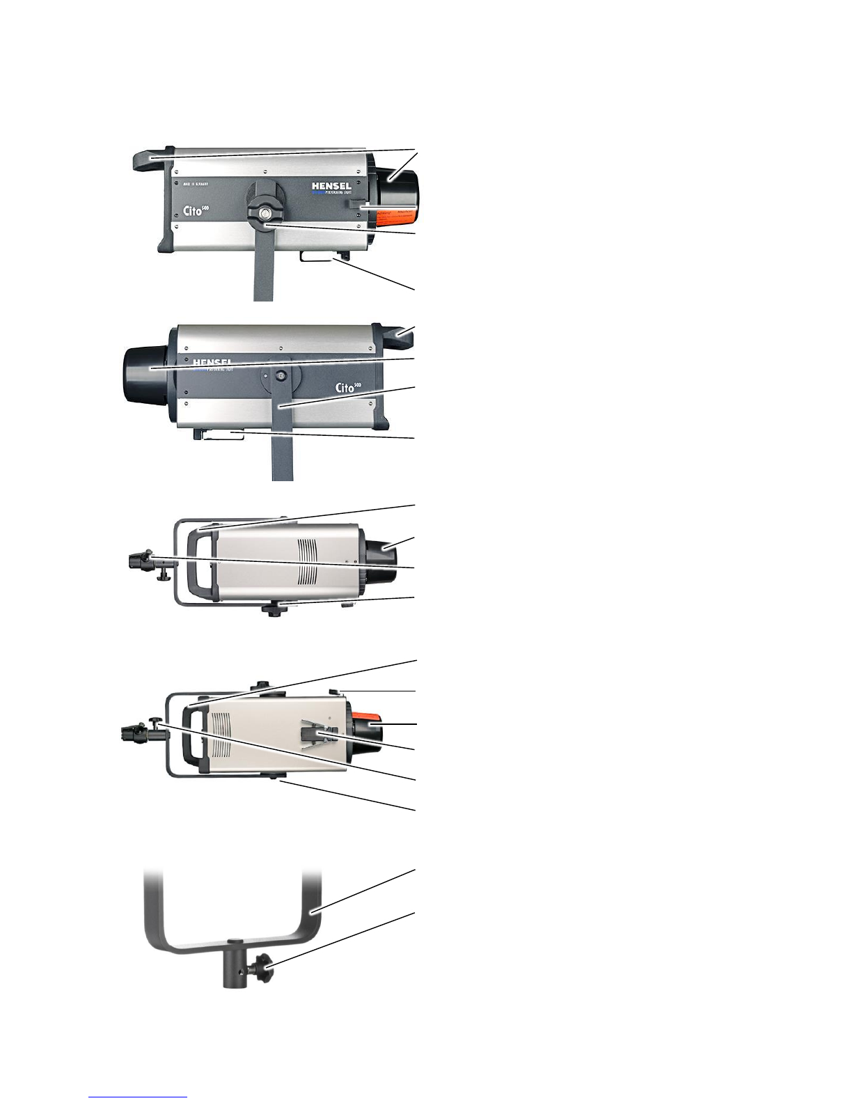
Equipment Description
Handle
Transport cap
Lever for reflector holder
U-bracket with locking device for tilt
head
Umbrella holder
Handle
Transport cap
U-bracket with locking device for tilt
head
Umbrella holder
Handle
Transport cap
Locking device for stand mounting
U-bracket with locking device for tilt
head
Handle
Lever for reflector holder
Transport cap
Umbrella holder
Locking device for stand mounting
U-bracket with locking device for tilt
head
U-bracket
Locking device for stand mounting
User manual Cito 500
Hensel-Visit GmbH & Co. KG 17
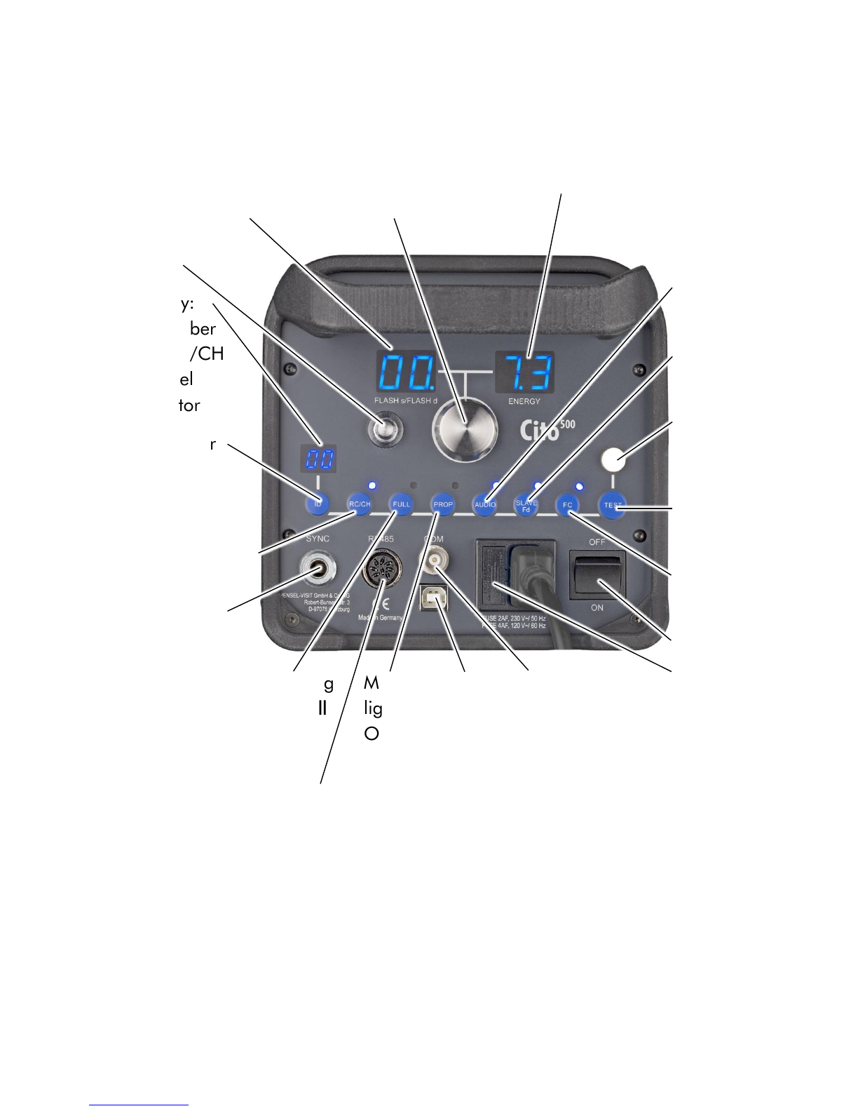
User Panel
Display:
flash
frequency,
flash duration
Rotary switch: output adjust-
ment, radio channel selection,
operating mode
Display:
set energy
Slave
Display:
ID number
and RC/CH
channel
indicator
ID number
selection
Radio receiver
/ channel se-
lection RC/CH
On/Off
Sync socket
Audio signal /
Audio On/Off
Slave / Slave
On/Off
Flash
readiness
indicator
Flash trigger
Test
Flash Check
On/Off
Power switch
On/Off
Fuse and
spare fuses
Modeling
light Full
On/Off
RS 485
socket
Modeling
light Prop
On/Off
USB
socket
TTL socket
(COM)

User manual Cito 500
18 HENSEL-VISIT GmbH & Co. KG
Scope of Delivery
The standard scope of delivery includes:
1 Cito 500
1 Flash tube single coated, plug-in style
1 Transport cap
1 Transport box
1 Glass safety dome, separately packed
1 Modeling light (according to customer requirement), separately
packed
1 Cable set: mains and sync cord
1 User Manual

User manual Cito 500
Hensel-Visit GmbH & Co. KG 19
Preparing for Initial Use
Please unpack the flash unit and control the completeness according to
scope of delivery. If something is missing, please get in contact with your
dealer.
For the following steps we recommend that you place the flash unit on a
flat surface or mount it to a stand mount.
Remove Transport Cap
CAUTION
Risk of fire when using with transport cap
Heat which may cause fire develops during the flash
process.
Remove transport cap before use.
Lever for reflector holder
Transport cap
Press the locking mechanism
of the reflector holder
against the spring tension
until reaching the end stop.
Pull out the transport cap
straight from the holder and
keep it for future usage.
Carefully return the locking
mechanism of the reflector
into its standard position with
the help of the spring
tension.

User manual Cito 500
20 HENSEL-VISIT GmbH & Co. KG
Protection of the flash tube during
transport
To remove the foam, pull it
straight off the flash tube.
Inserting Halogen Lamp for Modeling Light
Lamp socket for modeling light
Place the pins into the lamp
socket.
Push the lamp carefully into
place by alternating the
pressure on the pins until
contacting the end stop.
Table of contents
Other Hensel-Visit Camera Flash manuals


