Hercules Computer Technology GB 100 User manual

• f I •
I
'!
(
w
(])
Contents
(])
....,
b/J;>,
o.l
....,
o.l
:...
""
W.
....,
o.l
(])
~~~Q)~
il<~:s~,~
o
(])
.:::
zz::::.:io
1
Getti
ng St
arte
d
What
is the
Hercu
les Graphics Card? 1
Inventory
Checklist 1
How to install the Graphics Card 2
The Graphics Card's "Software Switch" 3
HBASIC 5
2
Fo
r Ad
va
nced Users
~
Configuring the Graphics Card 8
bJj Programming 9
~ 0
U
1"""""4
Interfacing
the
Graphics
Card
9
><
-0
~
s:::
Display Interface 9
...:l
...c:
~
Printer
Interface
13
~
~
~
~
GeneratingText
15
~
1"""""4
~
........
~
Generating Graphics
16
ro
C\l
<l.)
~
0
(])
C\l
(])
...j..J
A Appendix
00
w
~
~
o
w
(])
:...
~
I"""""4
Z
""
1 ']}oubleshooting
17
""
S
~
t:
~
<l.)
::S
;>, 0 2
Register
DescriptionsTable
18
~
fj
~
0
""
3 Application Notes
19
il<
'@
W.
il<
W.
W.
w.
(])
<l.)
....,
0 4 Modifying
the
Diagnostics
Pro
gram
22
w.
~
(])
,....
<l.)
1"""""4
(])
t-
~
~
:...
"'"
s:::
...:l
ti
....,
Ol
Ind
ex
23
~
w.
o.l
.
.......
U
..s::
;>, '2
W.
E-<
(])
~
(])
b/J
....,
Q)
:...
~
W.
o.l
<l.)
Ol
~
~
....,
0
..>::
~
w
~
I.Q
:...
"'@
......
0
I.Q
(])
r:...
il<
C\l
~
U

Edition 2.0
Here
ul
es
Co
mputerThchnology.
In
c.
mak
es
eve
ry effo
rt
ta ens
ur
e t
hat
these d
oc
um
ents
ar
e a
cc
urate.
Howeve
r,
because we
ar
e always striving to improve
our
pr
oducts,
we
ar
e unable
ta
guarant
ee
the
a
cc
uracy of the contents of these documents after the
date
of publication ami we
di
sc
la
im Iiability for
any changes. eITors or o
mi
ssions.
No reproduction o
fthi
s d
oc
urn
ent. in any form, is allowed without the ex
pr
ess
....
'lit
ten penni
ss
ion of
Hereules Computer Techno
lo
gy.
'"
1984
. Here
ul
es Computer
Th
ehnology. In
e.
All
rights ,-ese
rv
ed.
Here
ul
es Graphies Card. HBASIC ami Graph X
ar
e
trad
emarks of Hereules
Co
mputer
Th
ehnology.
IBM
is a registered
trad
emark of
Int
ernational
Bu
s
in
ess
Ma
chines.
Print
ed
in
the USA
1
Getting
Started
What
is
the
Hercules
Graphics
Card?
The Hercules Graphics Card is a high resolution graphics card for
the
IBM PC
monochrome display.
It
replaces the IBM monochrome display/
printer
adapter
and
is
compatible with its software. The Graphics Card uses
the
same style
high resolution monochrome character s
et
and comes with a parallel
printer
interface.
The Hercules Graphics Card offers two graphics pages each with aresolution
of
720h
x
348v.
Software supplied with the Graphics Card allows the use of the
BASIC graphics commands. A variety of graphics applications software
compatible with
the
Hercules Card
is
available from
other
vendors.
Inventory
Checklist
Verify
that
you have received the following items:
1 Graphics Card
1 owner's manual
1 HBASIC diskette
Please
fill
out the user registration card and
return
it to
uso
You
will receive
our newsletter and important product information for Graphics Cards users.
If
you did not receive a user registration card, then send us a postcard with
your name, address, Graphics Card serial number (which
is
stamped on
the
product), and
the
name ofyour dealer.
We
strongly urge you to read this manual before you
attempt
to insta
ll
or
operate
the
Hercules Graphics Card.
(You
may skip
Chapter
2.)
Ifyou
en-
counter any problems when using the Graphics Card, consult Appendix 1
before contacting your dealer
or
uso
1

1
Getting
Started
How
to
Install
the
Graphics
Card
A Follow these steps to insta
ll
the Graphics Card :
1 Remove the system unit cover following the
in
structions
2
3
4
5
6
7
8
9
10
2
in IBM
's
documentation or consult your dealer ifnecessary.
Make sure
that
the IBM Monochrome Display/
Printer
Adapter
or
any other video board
that
uses the same
screen buff
er
memory map is not
in
one ofthe expansion
slots.
Locate an empty expansion slot and ensure
that
there
w
ill
be enough clearance under the Graphies Card onee
it
is
installed.
(We
recommend sl
ot
2 in the PC
anel
slot 1
in
the
XT.)
Remove the metal plate
on
the back panel ofthe system
unit opposite the slot you have chosen for the Graphics
Card.
Firmly insert the Graphics Card into the slot.
Replace the bracket screw to sec
ur
e the card.
Set the switch settings
on
the motherboa
rel
for the Mono-
chrome Display or more than one monitor.
(Do
not count
the 64K
sc
reen buffer
on
the Graphics Card when
sett
in
g
the switehes for system memory.)
Make s
ur
e
that
there
is
no
other card in the system with
the same parallel
printer
port identity LPT1:.
If
your system is not an IBM PC,
eo
nsult the manual
anel
contact the factory
in
case ofany diffieulties.
Run the Diagnosties program.
Import
ant:
l
fyou
have a Hereules Graphics Card with the
model
number
GB100
stamped on the board, refer
to
Appen-
dix
.4
before running the Diagnostics program.
1
Getting
Started
The Graphics Card's
"Software
Switch"
The Hercules Graphics Card model number
GB
101
comes equipped with a
"software switch." The purpose of this switch is to allow you to manipulate the
Graphics Card with software to select one of
three
operating configurations.
Pay special
attent
i
on
to the information
in
t
hi
s section
on
setting the "software
switch." This is something
that
needs to be done EACH TIME
THE
COM-
PUTER
POWERS
UP
if you want to access either one
01'
both "pages" of
graphics
sc
reen buffer memory.
If
you forget to
set
the card into half
01'
full
mod
e, and you
attempt
to run any graphics software, your system
will
prob-
ably c
ra
sh.
If
this happens,
do
a "soft boot"
(CTRL-ALT-DEL)
or power up again.
The DIAG configuration is the
sta
te
which the card is automatically
in
after
power up. In this
co
nfiguration, the graphics capabilities
are
masked, a
nd
th
e Graphics Card emulates an IBM monochrome board for
text
only.
No
graphics software may be run while
in
this mod
e.
The
HALF
co
nfiguration makes the
fir
st
graphics page located
at
BOOOO-
B7FFF
accessible to graphics software. The seco
nd
graphics page
lo
cated
at
B8
000
-
BFFFF
is suppressed allowing the
pr
ese
nc
e of other video cards
provided
that
their
sc
reen buffer does not
occ
upy any portion of the first
graphics page. (This configuration allows the presence of an IBM
Co
lor Card
in the system
at
the same time as the Hercules Graphics Card.)
The
FULL
configuration makes the first and seco
nd
graphics pages access-
ible to graphies software.
A Fo
ll
ow
these steps to select one of the t
hr
ee eonfigurations:
1 'Ib select the DIAG
eo
nfigur
at
ion
, type
A>
HGC
DIAG
[E
NTER]
with the HBASIC
di
skette
in drive
A.
Alternatively, while
in
BASICA (not HBASIC), type
OUT
&H3BF,O
Note
SYSTEM
On power up, the Graphics Card will
be
in
the
DIAG corifiguration. Remember that
it
is necessary
to
be
in
the DIAG con,tiguration before attempting
to
run
the Diagnostic Program. However, this is
probably the only occasion you'll want
to
be
in
this
mode.
3
1 Getting Started
2
3
4
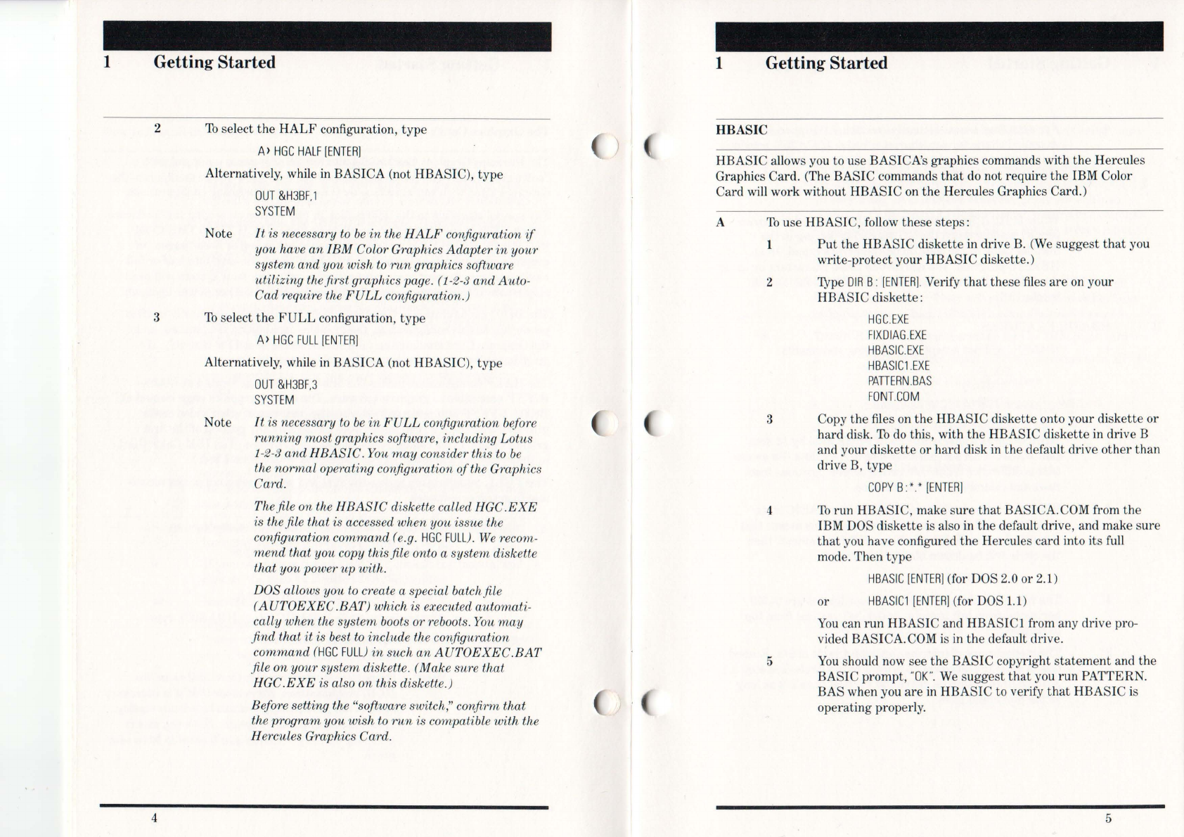
To
select the
HALF
configuration, type
A>
HGC
HAL
F[
ENTER]
Alternatively, while
in
BASICA (not HBASIC), type
OUT
&H3B
F,1
SYSTEM
Note
lt
is necessary
to
be
in
the
HALF
corifiguration
if
you ha
ve
an
I
BM
Color Graphics Adapter
in
your
system and you wish
to
run
graphics software
utilizing thefirst graphics pag
e.
(1-2-3 and Auto-
Cad require the
FULL
configuration.)
To
select the
FULL
configuration, type
A>
HGC
F
ULL
[ENTER]
Alternatively, while
in
BASICA (not HBASIC), type
OUT
&H3BF,3
Note
SYSTEM
lt
is necessary
to
be
in
FULL
configuration before
running
most graphics software, including Lotus
1
-2-3
and HBASIC. You
may
consider this
to
be
the normal operating conJiguration
of
the Graphics
Card.
Th
efi
le
on the
HBASIC
diskette
ca
ll
ed
HGC.EXE
is the.
file
that is accessed when you issue the
configuration command (e.g.
HGC
FU
L
L).
We recom-
mend
that you copy this file onto a system diskette
that you power
up
with.
DOS allows you
to
create a special batchfile
(AUTOEXEC
.BAT) which is executed automati-
cally when the system boots or re
boot
s.
You
may
.find that it is best
to
include the
cO'Y(figuration
command
(HGC
FULL)
in
such
an
AUTOEXEC
.
BAT
file on your system diskette. (Make sure that
HGC.
EXE
is also on this diskette.)
Before setting the "software switch," confirm that
the program you wish
to
run
is compatible with the
Hercules Graphics Card.
)
1 Getting Started
HBASIC
HBASIC allows you to use BASICA's graphics commands with the Hercules
Graphics Card. (The BASIC commands
that
do
not require the IBM Color
Card
will
work without HBASIC
on
the Hercules Graphics Care!.)
A
To
use HBASIC, follow these steps:
1
2
3
4
5
Put
the HBASIC diskette
in
drive B.
(We
suggest
that
you
write-protect your HBASIC diskette,)
'lYpe
DIR
B:
[ENTER]
.Verify
that
these
files
are
on
your
HBASIC diskette:
HGC
.
EXE
FIXD
I
AG
.
EXE
HBASIC
.EX
E
HBASIC1
.
EXE
PATIERN
.
BAS
FONHOM
Copy the files
on
the HBASIC diskette onto your diskette or
hard
disko
To
do
this, with the HBASIC diskette in drive B
and your diskette or hard disk
in
the default drive other than
drive
B,
type
COPY
B:
*.
*
[ENTER]
To
run HBASIC, make sure
that
BASICA.COM from the
IBM DOS diskette
is
also
in
the default drive, and make
sure
that
you have configured the Hercules card into its full
mode. Then type
HBASIC
[
ENTER]
(for DOS 2,0 or 2,1)
or
HBASICl
[ENTER]
(for
DOS
1.1
)
You
can run HBASIC and HBASIC1 from any drive pro-
vided BASICA,COM
is
in
the default drive.
You
should
now
see the BASIC copyright
statement
and the
BASIC prompt, "
OK".
We
suggest
that
you run PATTERN.
BAS when you
are
in
HBASIC to verify
that
HBASIC is
operating properly.
5
1
B
Getting Started
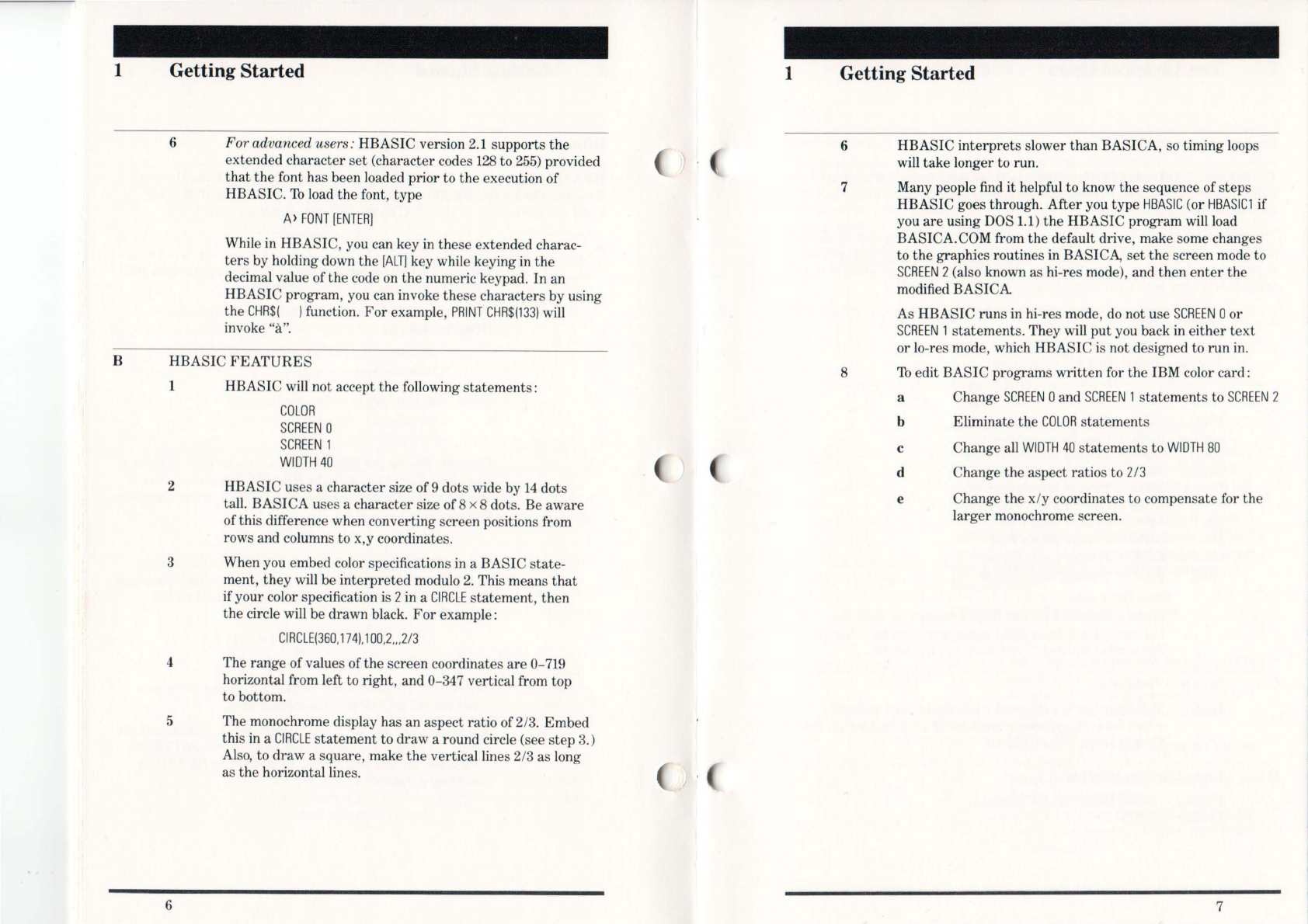
6 For advanced users: HBASIC version 2.1 supports
the
extended
character
set
(character codes
128
to
255)
provided
that
the
font has been loaded prior to the execution of
HBASIC. 'Ib load the font,
type
A)
FONT
[ENTER]
While
in
HBASIC, you can key
in
these
extended charac-
ters
by holding down the [
ALT
] key while keying
in
the
decimal value of the code on
the
numeric keypad. In an
HBASIC program, you can invoke these characters by using
the
CHR$(
)function.
For
example,
PRINT
CHR$(133)
will
invoke
"a".
HBASIC
FEATURES
1 HBASIC will not accept the following
statements:
2
3
COLOR
SCREEN
0
SCREEN
1
WIDTH
40
HBASIC uses a character size of9 dots wide by
14
dots
tall.
BASICA
uses a character size of8 x 8 dots. Be
aware
ofthis difference when converting screen positions from
rows and columns
to
x,y coordinates.
When you embed color specifications in a BASIC
state-
ment,
they
will be
interpreted
modulo
2.
This means
that
ifyour color specification is 2in a
ClRC
LE
statement,
then
the circle will be drawn black.
For
example:
CIRCLE(360
,
174)
,
100,2"
,
2/3
4 The range ofvalues ofthe screen coordinates
are
0-719
horizontal from left to right, and 0-347 vertical from top
to bottom.
5 The monochrome display has an aspect ratio of2/
3.
Embed
this
in
a CI
RCLE
statement
to
draw
a round circle (see
step
3.)
Also, to
draw
a square, make
the
verticallines 2/3 as long
as the horizontallines.
6
1 Getting Started
6
7
8
HBASIC
interprets
slower than BASICA, so timing loops
will take longer to run.
Many people find
it
helpful to know the sequence of
steps
HBASIC goes through.
After
you type
HBASIC
(or
HBASIC1
if
you
are
using DOS 1.1)
the
HBASIC program will load
BASICA.COM from the default drive, make some changes
to
the
graphics routines in BASICA,
set
the
screen mode to
SCREEN
2(also known as hi-res mode), and then
enter
the
modified
BASICA
As HBASIC
runs
in
hi-res mode,
do
not use
SCREEN
0or
SCREEN
1
statements.
They will
put
you back in
either
text
or
lo-res mode, which HBASIC is not designed to
run
in.
'Ib edit
BASIC
programs
written
for the IBM color card:
a Change
SCREEN
0and
SCREEN
1
statements
to
SCREEN
2
b
c
d
e
Eliminate the
COLOR
statements
Change all WI
DTH
40
statements
to
WIDTH
BO
Change the aspect ratios to 2/3
Change the x/y coordinates to compensate for the
larger
monochrome screen.
7
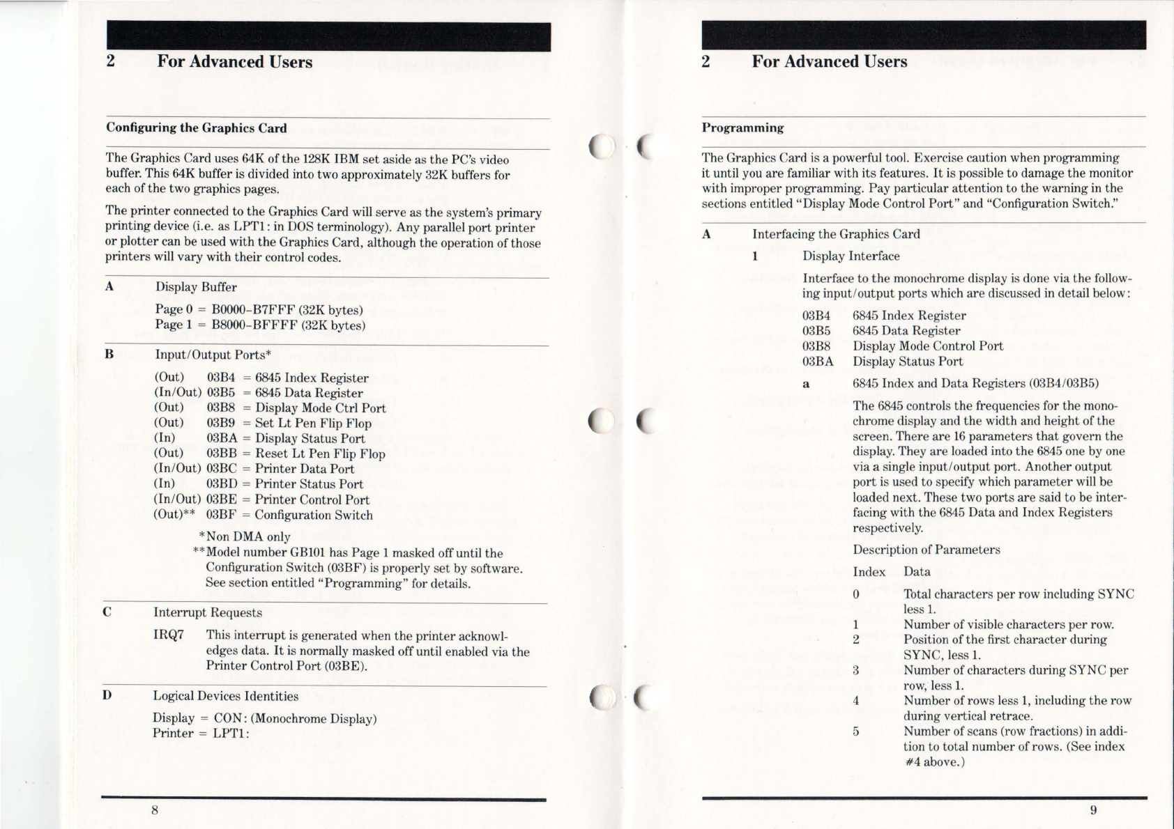
2 For Advanced Users
Configuring
the
G
raphi
cs
Ca
rd
The Graphics Card uses 64K ofthe
128K
IBM
set
aside as the PC's video
buffer. This 64K buffer
is
divided into two approximately 32K buffers for
each ofthe two graphics pages.
The
printer
connected to the Graphics Ca
rd
will
serve as the system's primary
printing device (i.e. as LPT1: in DOS terminology). Any parallel port
printer
or plotter can be used with the Graphics Card, although the operation of those
printers will vary with
their
control codes.
A
B
C
D
Display Buffer
Page 0 =
BOOOO-B7FFF
(32K bytes)
Page 1 =
B8000-BFFFF
(32K
bytes)
Inpu
t/O
utput
Ports
*
(Out)
03B4
=
6845
Index Register
(In/Out) 03B5 =
6845
Data Register
(Out) 03B8 = Display
Mode
Ctri
Port
(Out) 03B9 =
Set
Lt
Pen Flip Flop
(In) 03BA = Display
Stat
us
Port
(Out) 03BB = Reset
Lt
Pen Flip Flop
(In
/
Out)
03BC =
Printer
Data
Port
(In) 03BD =
Printer
Status
Port
(InIOut) 03BE =
Printer
Control
Port
(Out)** 03BF =
Co
nfiguration Switch
*Non DMA only
**Model number
GB101
has Page 1 masked off until the
Configuration Switch (03BF)
is
properly
set
by software.
See section entitled "Programming" for details.
Int
errupt
Requests
IRQ7 This
interrupt
is generated when
the
printer
acknow
l-
edges data.
It
is normally masked off until enabled via the
Printer
Control
Port
(03BE).
Logical Devices Id
entit
ies
Display = CON: (Monochrome Display)
Printer
=
LPTl:
8
2 For Advanced Users
Programming
The Graphics Card is a powerful too\. Exercise caution when programming
it until
yo
u are familiar with
its
features.
It
is possible to damage the monitor
with improper programming.
Pay
particular attention to the warning in the
sections entitled "Display Mode Control
Port"
and "Configuration Switch."
A Interfacing the Graphics Card
1 Display Interface
Interface to
the
monochrome display
is
done via the follow-
ing input/output ports which are discussed in detail below:
03
B4
6845
Index Regi
ste
r
03B5
6845
Data Register
03B8 Display Mode Control
Port
03BA Display Status
Port
a
6845
Index and
Data
Registers
(03B4
/
03B5)
The
6845
controls the frequencies for the mono-
chrome display and the width and height of the
screen. There are
16
parameters
that
govern the
display. They
are
loaded into the
6845
one by one
via a single input/output port. Another output
port
is used to specify which parameter will be
loaded next. These two ports
are
said to be inter-
facing with the
6845
Data and Index Registers
respectively.
Description of
Parameters
Index Data
o Total characters
per
row inc\uding SYNC
less
1.
1 Number of visible cha
ra
cters
per
row.
2 Position ofthe first character during
SYNC, less
1.
3 Number of characters during SYNC
per
row
,"
less
1.
4 Number
ofrows
less 1, inc\uding the row
during vertical retrace.
5 Number of scans (row fractions) in addi-
tion to total number ofrows. (See index
#4
above.)
9

2 For Advanced Users
10
6
Number
ofvisible rows.
7 Row
number
to begin
the
retrace,
less
1.
(This will always last
16
scans.)
8 Always
output
2.
(Consult 6845
data
sheet.)
9
Number
ofscans
per
row, less
1.
10
First
scan
where
the
cursor will overlay a
character.
11
Last
scan where
the
cursor
will overlay a
character.
12
Always
output
O.
(Consult 6845
data
sheet.)
13
Always
output
O.
(Consult 6845
data
sheet.)
14
Offset of
the
cursor
position in
the
display
buffer
(H).
15
Offset of
the
cursor
position in
the
display
buffer (L).
16
Offset into
the
buffer when lightpen
tripped
(H).
17
Offset into
the
buffer when lightpen
tripped (L).
Note
i The monochrome display requires a
scan
to
be approximately 54 microseconds.
ii
The total number
of
rows and scans
must
be
adjusted
to
allow enough timefor
the screen
to
be
updated
50
times per
second.
iii The local oscillator on the Graphics
Card will generate a time base
of
0.5625
microseconds per character
in
text mode
and1 microsecond per character
in
bit-mapped mode.
iv
In
bit-mapped mode, one character
is
16
dots wide and 4 scans tall. In text
mode, it
is
9 dots wide and
14
scans tall.
v See Appendix 3 for typical parameter
values.
2 For Advanced Users
b Display Mode Control
Port
(03B8)
This
output
port
sets
the
mode ofoperation for
the
Graphics Card.
Bit Options
o Not used
1 0 =
text
mode (Power on
default)
1 = graphics mode
(Note: The 6845
must
be
reprogrammed
each time
this
bit
changes value.)
2 Not used
3 0 = blank
the
screen (Power on default.)
1 = activates
the
screen
(This
bit
is useful when changing modes.
By keeping
the
screen blank for
aperiod
oftime,
the
change from
text
to graphics
modes can be done without any screen
bounce.)
4
Not
used
5 0 =
turn
off
the
text
blinker (Power
on
default.)
1 =
turn
on
the
text
blinker
(This blinker has no effect on
the
cursor.
Every
character
whose
attribute
indi-
cates blinking, will now blink.)
6
Not
used
7 0 =
Page
0 (Power on default.
Start
display
at
BOOOO.)
1 =
Page
1
(Start
display
at
B8000. This
bit
selects
the
active display buffer
on
the
Graphics Card.)
Note
Be particularly careful when changing
between text and graphics modes. You
must
simultaneously:
-program
the Display Mode Control
Port bit 1, and
-program the 6845 with the proper
parameters.
When you switch between text
and
graphics
modes, your monitor is subject
to
some
11

2 For Advanced Users
c
12
undefined horizontal and vertical fre-
quencies. For this reason
we
suggest
that you
do
not use high levellanguages
to
control the Display Mode Control Port
bit 1. (This does not include memory
access which can
be
done
in
any
lan-
guage.) See Appendix 3 for a listing
of
the correct way
to
change modes.
Display
Status
Port
(03BA)
This input
port
is used to sense the real time
status
of the monochrome display.
Bit Conditions
o
1
2
3
4
5
6
7
o= normal
character
1 = SYNC (Screen is temporarily
blanked.)
Not used
Not used
o= dots off
1 = dots on
(This bit can be used as a software check-
point to verify
that
the monochrome
display is receiving an active video
signal.)
Not used
Not used
Not used
o= vertical
retrace
(Screen is tempo-
rarily blanked.)
1 = active displ
ay.
(This information is
useful when software wants to make
sure
that
the
screen is blanked.)
2 For Advanced Users
2 The
printer
interface uses
the
following
input/output
ports:
03BC
03BD
03BE
a
b
Printer
Data
Port
Printer
Status
Port
Printer
Control
Port
Printer
Data
Port
(03BC)
An
output
to this
port
willlatch the value from
the
data
bus to
the
printer
. The actual pin condi-
tions
are
returned
when input. This feature is
used to verify the integrity of
the
data
path.
Printer
Status
Port
(03BD)
This is an input
port
only.
Bit Conditions
o
Not
used
1
Not
used
2
Not
used
3 0 =
printer
error
1 = normal operation
4 0 =
printer
not
attentive
1 =
printer
is listening
5 0 = normal operation
1 = out of
paper
6 0 = accepting
data
1 = ready for more
7 0 =
printer
is busy, not selected
or
in
error
1 = normal operation
13

2 For Advanced Users
c
d
14
Printer
Control
Port
(03BE)
This is an input/output port.
Bit Actions
o
1
o= strobe the
printer
to accept data
at
the data latch
1 = release the strobe (Power
on
default.)
o= auto line feed
1 = remote line feed control (Power
on
default.)
2 0 = initialize the
printer
(Power
on
default.)
1 = release the
printer
for normal
operation
3 0 = deselect the
printer
1 = select the
printer
(Power
on
default.)
4 0 = mask off IRQ7 (Power
on
default.)
1 = enable IRQ7 when the printer is
ready for data
5 Not used
6 Not used
7 Not used
Configuration Switch (03BF)
This port accesses
the
software switch
that
allows
one of
three
configurations of the Graphics Card's
memory map and protects against the accidental
setting of graphics mode.
Bit
o
1
Option
o= (power
on
default) prevents the
setting of graphics mode (bit 1 of Display
Mode Control Port)
1 = allows the setting of graphics mode
bit (bit 1 of Display Mode Control Port)
o= (power
on
default) mask Page 1
(B8000-BFFFF) out of the memory map
and prevent the setting of page bit (bit 7
ofDisplay Mode Control Port)
1 = bring Page 1 (B8000-BFFFF) into
the memory map and allow the setting of
page bit (bit 7 of
Di
splay Mode Control
Port)
2
B
For Advanced Users
How the Dots Are Generated: Text
In
text
mode, the display buffer
is
used to store the character codes
and the
attrib
ute codes for displayed characters. The offset of the
storage is:
BOOOO-BOFFF
(4K
bytes)
The
text
display is 80 characters wide and
25
lines long. All the
characters are stored contiguously using up
160
bytes
per
line.
For
each character, one byte is used for the character code and one for
the attribute.
Offset ofthe character code of a character:
=
160
*
(LINE
-1) + 2 *(COLUMN -1)
Offset ofthe attribute of a character:
=
160
*
(LINE
-1) + 2 *(COLUMN -1) + 1
where
LINE
is
between 1 and
25
COLUMN is between 1 and
80
The Graphics Card has a hardware character generator which can
do
256
different characters specified by the character codes. The
re
is
an
attribute
decoder which can underline, reverse video, blank,
bold face, or blink any character. The character generator conforms
to the standard IBM PC character font.
The
attribute
decoder follows these rules:
7 6 5 4 3 2 1 0 Attribute Codes
B 0 0 0 I 0 0
B 0 0 0 I 0 0
B 0 0 0 I 1 1
B 1 1 1 I 0 0
where I = 0 for normal body
I = 1 for bold
body.
0 Blank
1 Underline
1 Normal Display
0 Reverse Video
If
the blinker
is
off
(i.
e.
the display mode control port bit
5 = O)then
B = 0 for normal background
B = 1 for bold background
If
the blinker is
on
(display mode control port bit 5 =
1)
then B = 0 for
no
blink
B = 1for blinking
15

2
C
For Advanced Users
How
the
Dots
Are
Generated : Graphics
Once
the
Graphics Card is in the bit-mapped mode,
the
display
buffer can store two pages, or two screens using one bit
per
dot.
These two pages can be al
ternate
ly displayed.
While a page or screen is being displayed, any alteration to
the
buffer for
that
page will be shown
on
the
display.
For
the page not
being displayed, changes to
it
will be shown only when it is
selected.
The page selection is done by using bit 7 of the Display Mode Control
Port
in
the
following manner:
ofor
Page
0
1for
Page
1
The buffer
area
is allocated as folIows:
Page 0 =
BOOOO-B7FFF
Page 1 = BSOOO-BFFFF
The offset (into
the
page) ofthe byte containing dot (x,y) in each
page is:
[2000H *(Y
MOD
4)]
+ [90 *
INTEGER
(Y/
4)]
+
[INT
EGER
(X
I
S)
]
and
the
bit
in
the
byte
that
stores
the
dot is bit position
7 -
(X
MOD
S)
where x is between 0 and
719
y is between 0 and 347
EXAMPLE:
The offset of (300,250) is
[2000H *(250
MOD
4)]
+ [90 *
(INTEGER
(250
/4))] +
[
INTEGER
(300/S)]
= [2000H *
(2)]
+
[90
*
(62)]
+
(37)
= 4000H +
5617
= 4000H +
15FIH
=
55FlH
and bit position is
7 -
(300
MOD
S)
= 7 -
(4)
=
3.
16
A Appendix 1
'froubleshooting
If
you encounter any problems when using the Graphics Card, pIease review
the
fo
ll
owing:
A
B
C
You
cannot
run
grap
hics software Wl'itten solely for
the
IBM Col
or
Grap
hi
cs
Adapter
(e.g. Microsoft's
Flig
ht Simulator.) Make
sure
that
you have the
Hercu
les version of
the
graphics program you
would like
to
run
(e.g. Version
lA
of 1-2-3).
Make su
re
that
you do not have an IBM Color Graphics
Adapter
or
Monochrome Display/
Printer
Adapter
in
the
system
at
the same
time
as
the
Hercules Graphics Card. (This also applies to
other
graphics cards which use
the
same screen buffer address as
the
Graphics Card.)
Check these points when using
HBASIC:
1 Use the
"HBASIC"
fi
le with DOS 2.0 or DOS 2.1 and use the
"HBASICl"
file with DOS
1.1.
(HBASIC does not work
with DOS 1.0.)
2 Run
HBASIC
in
SCREEN
2mode only.
3
4
Do
not used
HBASIC
version 1.0,
1.1
, 2.0 with a disk
emul
ator
like JFORMAT.
Check your switch settings and make
sure
that
they
are
set
for the monochrome display. (See "How to Install the
Graphics Card.")
17
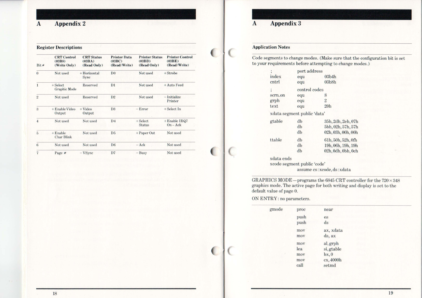
A Appendix 2
Regis
ter
Desc
ription
s
Bit#
o
2
3
4
5
6
7
CRTCo
nt
rol
(03ß8)
(Write Onl
y)
Not used
+ Select
Graphic
Mode
Not used
+ Ena
bl
e
Vid
eo
Ou
tput
Not used
+ Enable
Char Blink
Not used
Page #
18
CRT Sta
tu
s
(o3
ß
A)
(R
ea
d Only)
+ Horizontal
Sync
Reserved
Reserved
+
Vid
eo
Output
Not used
No
t used
Not used
-VSync
Pri
nt
er D
ata
(03BC)
(R
ea
d/W
rite)
00
D1
02
03
04
05
06
07
Prin
te
r Status
(03
ß
D)
(R
ea
d Only)
Not used
Not used
Not used
-
Err
or
+ Select
Status
+ Paper Out
-Ack
-
Bu
sy
Prin
te
r Control
(03
ßE
)
(Read/
Writ
e)
+Strobe
+ Auto Feed
-Initial
ize
Printer
+ Select In
+ Enable IRQ7
On
-Ack
Not used
Not used
Not used
A Appendix 3
Applic
ation
Notes
Code segments to change modes. (Make sure
that
the configuration bit
is
set
to your requirements before at
te
m
pt
ing to change modes.)
index
cntrl
scrn...on
grph
text
port address
equ 03b4h
equ 03b8h
control codes
equ 8
equ 2
equ 20h
xdata segment public 'data'
gtable
ttable
xdata ends
db
db
db
db
db
db
35h, 2dh, 2eh,
07h
5bh,02h,57h,57h
02h,03h,00h,00h
61h,50h,52h,Ofh
19h,
06h
,
19
h,
19h
02h,
Odh
,
Obh
,
Och
xcode segment public 'code'
assume cs: xcode,ds:
xdata
GRAPHICS
MODE-programs
the
6845
CRT controller for the
720
x
348
graphics mode. The active page for both writing and display is
set
to
the
default value of page O.
ON
ENTRY:
no parameters.
gmode proc near
push es
push ds
mov ax, xdata
mov ds, ax
mov al,grph
lea si,gtable
mov bx,O
mov cx,4000h
caH
setmd
19

A Appendix 3
pop
pop
ret
grnode endp
ds
es
TEXT
MODE-programs
the 6845
anel
CRT
control
register
to proeluce
text
mode.
ON
ENTRY:
no
parameters.
tmode proc
near
push es
push ds
mov ax, xdata
mov ds, ax
mov al,
text
lea si,ttable
mov bX,720h
mov cx,2000
ca
ll
setmd
pop ds
pop es
ret
tmode endp
setmd proc near
sets
mode
to
graphics or
text
depending on
al
si
=
parameter
table
cx
=
number
ofwords to be cleared
bx = blank value
push ds
push es
push ax
push bx
push
cx
change mode
but
without
scrTLon
mov dX,cntrl
out dX,al
20
A Appendix 3
initialize
the
6845
mov aX,ds
mov eS,ax ;also point es: si
;to
parameter
;tab
le
mov dX,index
mov cx,12 ;
12
parameters
to
;be
output
xor ah,ah
;starting
from
;reg
.O
parms:
mov al
,ah
out dX,al ;output
register
;number
in
c dx
l
oelsb
out dX,al ;output
data
inc ah
;next
value
dec dx
loop parms
pop cx ;clear the buffer
mov
aX,ObOOOh
cld
mov eS,ax
xor di,di
pop ax
rep
stosw
sc
rTLon
,page 0
mov dX,cntrl
pop ax
add al,scrTLon
out
dX
,
al
pop es
pop ds
ret
setmel enelp
xcode ends
21

A Appendix 4
Mo
di
fying the Diagnostics Program
Ifyou
have a Hercules Graphics Card model number
GB
100,
do
not
attempt
to run
the
IBM diagnostic program versions 1.0,
1.01,
1.0201'
1.03
without
making
the
changes described below. (Diagnostics version 2.0 can be run
without modification.)
A Make a copy of the diagnostics program by formatting a blank
diskette and using the
DISKCOPY
01'
COPY
command described in
the
DOS manual.
B Boot DOS and wait for
the
A
>.
e
Insert
the
HBASIC diskette
in
drive A:.
D
Insert
your copy of the diagnostics diskette in drive B:.
E Execute the
"FIXDIAG.EXE"
program on drive A: by typing
FIXDIAG
[ENTER)
F
To
run
the
diagnostic program, put your modified diagnostic copy in
drive A:. Hold down
the
[
ALT)
,
[CTRL)
and
[DE
L)keys simultaneously
to
reset
the system and
start
the diagnostics program.
G Consult your IBM Guide to Operations to
step
through
the
diag-
nostics program.
22
Index
Attribute
Codes
15
AUTOEXEC.BAT 4
BASICA.COM 5
Configuring
the
Card 3
DIAG Configuration 3
HALF
Configuration 4
FULL
Configuration 4
Diagnostics
2,22
Display Buffer 8
Display Interface 9
Display Mode Cntrl.
11
Display
Status
Port
13
DOS Versions 5,17
FIXDIAG.EXE
5,22
FONT.COM 6
Graphics Mode
16
from Assembler
21
HBASIC.EXE
5,
17
HBASICl.EXE
5,
17
HGC.EXE
4,5
IBM Color Card
3,
17
Color Card Software 7
1/0
Ports
8
Installation 2
Interrupt
Requests 8
Inventory 1
Logical Device I.D. 8
Lotus
1-2-3
4,17
PATTERN.BAS 5
Printer
Cntrl.
Port
14,18
Printer
Data
Port
13,18
Printer
Interface
13
Printer
Status
Port
13,18
Programming 9
6845
Registers 9
Text Mode
15
23

24
Limited
Wa
r
ranty
Here
ul
es Compu
te
r1
ech
nology
(I
-ICT) wa
rr
ants this Hereul
es
Graphics
Ca
rd to be in good
wo
rk
in
g order for
ape
ri
od of two
ye
ars
fr
om
the d
at
e of purehase from HCT or an authorized
Graphics Card dealer. Sho
ul
d t
hi
s Gr
ap
hics Card fa
il
to be in
good
wo
r
ki
ng order
at
any time during the two year period,
HCT
wi
ll
,
at
its option, rel
>air
or replace it
at
no additional
ch
arg
e, exce
pt
as
s
et
out bel
ow
. Replacement p
art
s
wi
ll
be
either re
co
nditioned or ne
w,
and the replaced
part
s w
ill
become
the prope
rt
y of HC
T.
T
hi
s
li
mited
wa
rr
anty do
es
n
ot
cover
Graphics Cards damaged fr
om
a
cci
dent, dis
ast
er,
mi
suse, abuse
or unauthorized mooific
at
i
on
s.
Li
mi
te<
IWa
rra
nty
se
rvice may
be
obtained by de
liv
ering t
hi
s
product to an authorized Grap
hi
cs Ca"d d
ea
ler along with
Pr
oo
fof Purchase Date. If the prod
ll
ct is ma
il
ed to HC
T,
you
must o
bta
in an RMA
!l
umber from HCT, send it freight prepaid
an
el
you
mll
st
in
su
re
the prodllct or ass
urn
e the risk of loss or
damage
in
transit
am
i you must "eturn it in its origin
al
shipping
co
nta
in
er, or an eq
ui
valent.
A
ll
ex
pr
ess a
nd
implied war
ra
nties
fo
r the Graphics Card ,
in
cluding war
ra
nti
es
of merchantibility an
el
fi
tness for a
part
i
cu
l
ar
purpose,
ar
e limited to two y
ear
s from the
dat
e of
purchase. No wa
rr
ant
ies,
wh
ether ex
pr
ess
or
imp
li
ed, w
ill
ap
pl
y after this peri
od
. Some
sta
tes do not a
ll
ow
li
mi
tat
ions on
how long an
im
pl
ied
warrant
y lasts, so these limitations may
n
ot
ap
pl
y to y
ou
.
1
ft
hi
s Graphics Card is not in g
ood
working order, your sole
remedy sha
ll
be
repair or re
pl
acement as described above. In
no event
wi
ll
HCT
be
li
able to you
fo
r damages arising
out
of
the use
or
inab
ili
ty
to use t
hi
s product.
So
me s
tat
es
do n
ot
a
ll
ow
the exc
lu
sion or limit
at
ion ofinci-
dental or
co
nseq
ll
ential damages for
co
nsumer
pr
odu
ct
s, so
these l
imi
tat
i
on
s may n
ot
apply to
YO
t!
.
Her
eu
les
Co
m
pu
ter
Th
chnology
2
550
N
in
th Street
ße,
-k
eley, CA 947
10
To rece
iv
e o
ur
free newsle
tt
er, send yo
ur
name and a
ddr
ess with the
serial number on yo
ur
Graphi
cs
Card to Here
ul
es
Co
mpu
te
r
Tec
hnology,
255
0 Ninth St. , Be
rk
eley, CA
94
71
0.
25
This manual suits for next models
1
Table of contents
Popular Video Card manuals by other brands


Diamond Multimedia
Diamond Multimedia AMD HD 5450 installation manual

Gigabyte
Gigabyte GV-RX16P128P-RH user manual

Gigabyte
Gigabyte GV-R645D3-512I user manual

Gigabyte
Gigabyte GV-R695D5-2GD-B user manual

Diamond Multimedia
Diamond Multimedia ATI Radeon Stealth 2400PRO256PET Specification sheet

4D systems
4D systems Picaso MD1 user manual


