www.4dsystems.com.au
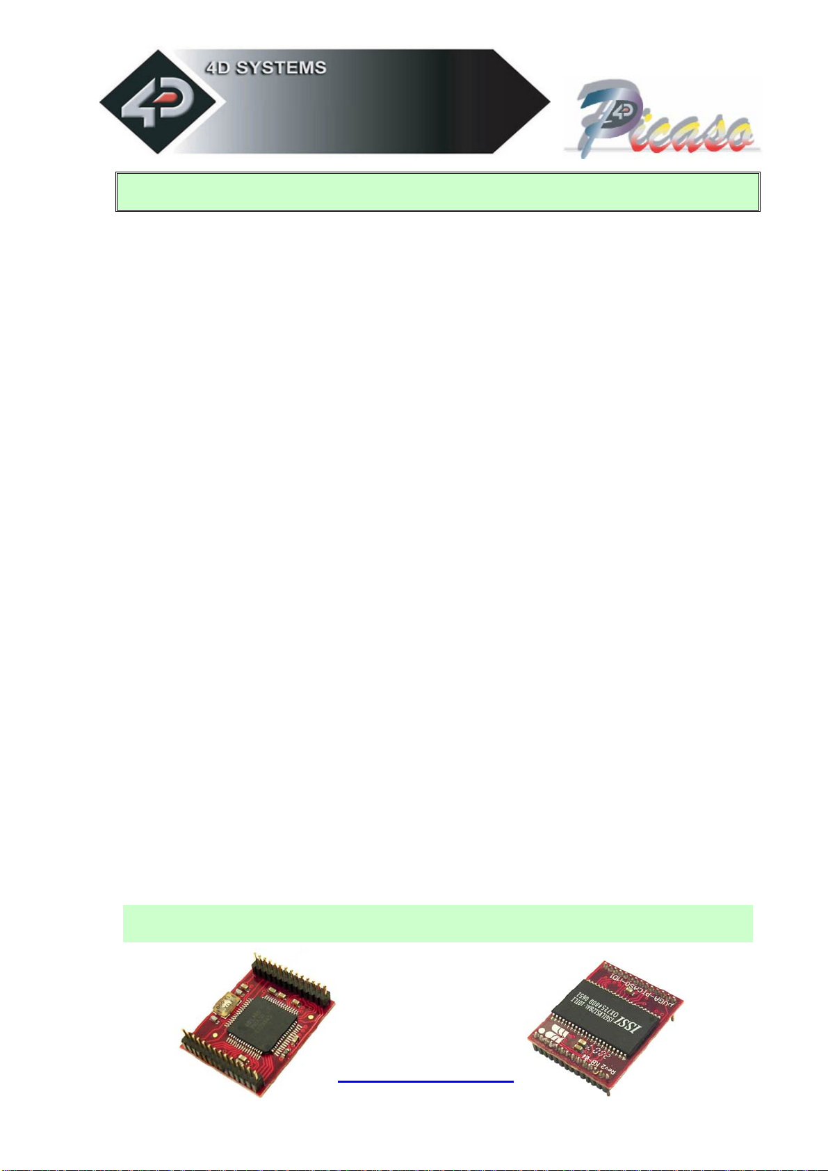
µVGA-PICASO-MD1
5
2Features
The µVGA-PICASO-MD1 module is aimed at being integrated into a variety of different
applications using a wealth of features designed to facilitate the designer to quickly and
cost effectively complete a product and thus reduce ‘time to market’. These features are as
follows:
Intelligent and fully integrated VGA/SVGA Display Graphics Controller.
Tiny 28 pin module, powered by the 4D LABS PICASO chip. A powerful DSP/Controller
based multi purpose graphics engine.
Low Power design. 3.0Volts to 3.6Volts input supply @90ma.
256 Colours with standard resolution modes for QVGA (320x240), VGA (640x480) and
SVGA (800x600, to be implemented in the near future). The µVGA-PICASO-MD1
supports multiple resolutions with in the same module. Resolutions are selectable during
run time under host control. Resizable viewing window allows partial/full screen control.
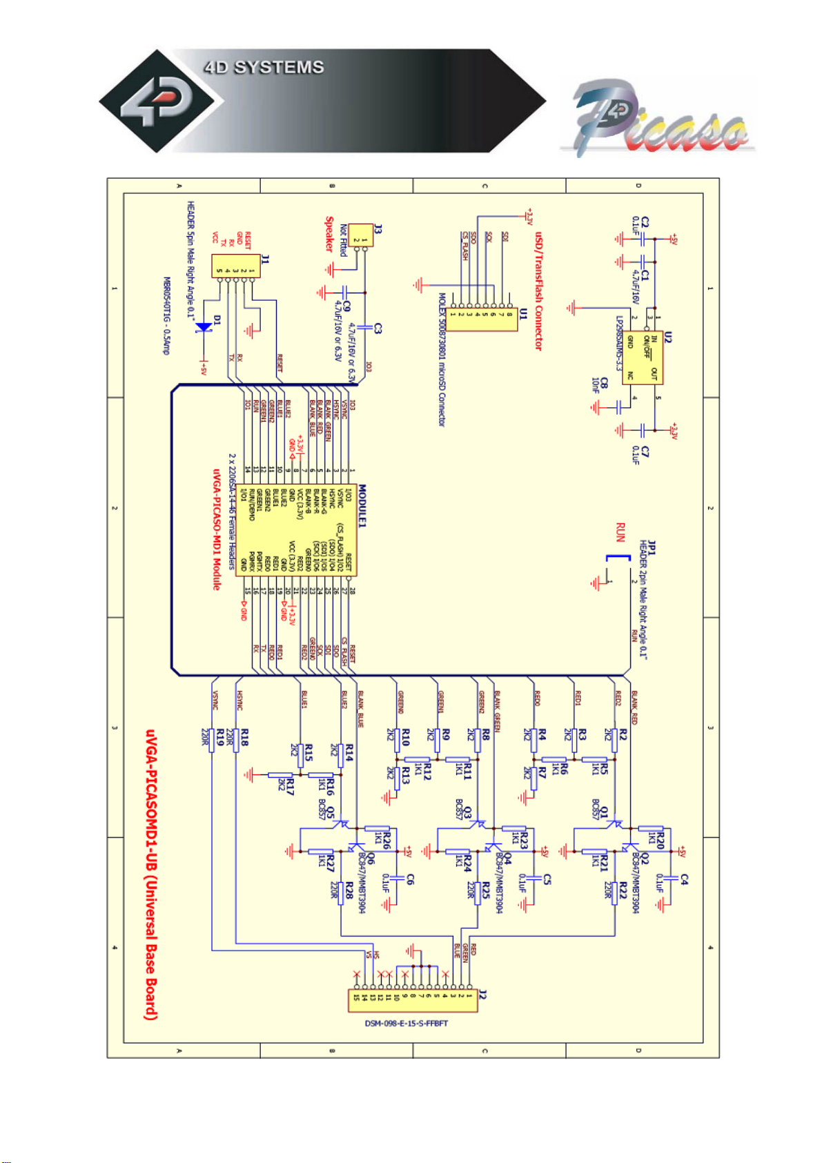
The digital video signals, RED0:RED2, GREEN0:GREEN2, BLUE1:BLUE2, HSYNC, VSYNC
and BLANK(R,G,B), facilitate using a simple Resistor-DAC to drive any standard VGA
monitor.
512K bytes of onboard SRAM for video memory allows 8 pages for QVGA, 2 pages for
VGA and 1 page for SVGA resolutions. Utilising the multiple pages allows double
buffering which can be used for smooth animations and windowing of menu systems.
RX and TX signals (TTL levels) provide a simple serial host interface. The serial interface
allow the µVGA-PICASO-MD1 graphics module to be connected to any host controller
such as a PIC, AVR, STAMP, ARM, Propeller just to name a few as well as a PC. The host
controls the module by sending simple serial commands. Auto baud rate detection from
2400 baud to 1Mbit/sec.
Powerful, easy to use and understand built in graphics functions allow drawing of lines,
rectangles, circles, ellipses, text, images, icons, user defined bitmaps and much more…
SPI signals (SDI, SDO, SCK) allow the module to be connected to a number of SD and
MMC memory cards (from 64Mb up to 4Gb) that can store images, icons, and other
graphics objects.
Future upgrades and enhancements are easily achieved by uploading PmmC
(Personality module micro Code) files. PmmC files allow the PICASO chip to be
uploaded with the latest micro-Code firmware.
System designers can incorporate the µVGA-PICASO-MD1 module directly into their
application, saving space and cost. Reference designs enable the user to create a
platform to incorporate the µVGA-PICASO easily.
NOTE: Usable resolutions are; QVGA: 310x210, VGA: 620x420 and SVGA: 800x560. These
resolutions are chosen to maximise the number of display pages from the video RAM.