ESD electronic PMC-DVI User manual
PMC-DVI Hardware Manual Rev. 1.0
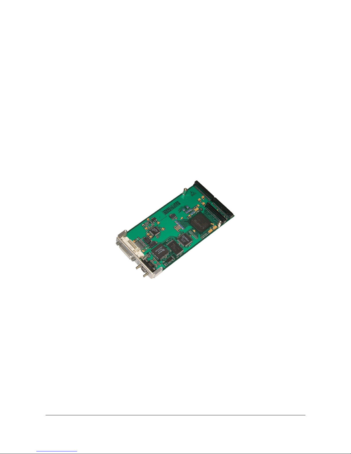
PMC-DVI
DVI-Graphics Card
Hardware Manual

PMC-DVI Hardware Manual Rev. 1.0
Document File: I:\texte\Doku\MANUALS\PMC\PMC-DVI\Englisch\PMC-DVI_10.en9
Date of Print: 07.04.2003
PCB Version: PMCVGA Rev. 1.0
Changes in the chapters
The changes in the user’s manuallisted below affect changes in the hardware,as well as changes in the
description of the facts only.
Chapter Changes versus previous version
-First version
-
Further technical changes are subject to change without notice.

PMC-DVI Hardware Manual Rev. 1.0
N O T E
The information in this document has been carefully checked and is believed to be entirely reliable. esd
makes no warranty of any kind with regard to the material in this document, and assumes no
responsibility for any errors that may appear in this document. esd reserves the right to make changes
without notice to this, or any of its products, to improve reliability, performance or design.
esd assumes no responsibilityfor the use ofany circuitryother than circuitrywhich is part ofaproduct
of esd gmbh.
esd does not conveyto the purchaser ofthe product described herein anylicense under the patent rights
of esd gmbh nor the rights of others.
esd electronic system design gmbh
Vahrenwalder Str. 207
30165 Hannover
Germany
Phone: +49-511-372 98-0
Fax: +49-511-372 98-68
E-mail: [email protected]
Internet: www.esd-electronics.com
USA / Canada
esd
PMB 292
20423 State Road 7 #F6
Boca Raton, Florida 33498-6797
USA
Phone: +1-800-732-8006
Fax: +1-800-732-8093
E-mail: [email protected]

PMC-DVI Hardware Manual Rev. 1.0 1
Contents
1. Overview .................................................................3
1.1 Description of the PMC-DVI Module .........................................3
1.2 Summary of Technical Data .................................................4
1.2.1 General Technical Data ..............................................4
1.2.2 PCI-Bus .........................................................5
1.2.3 Graphics Card ....................................................5
1.2.4 Software Support ..................................................5
1.2.5 Order Information ..................................................6
2. Hardware Installation .......................................................7
3. Front Panel View with LED-Display ...........................................8
3.1 LEDs and Connectors in the Front Panel ......................................8
4. Connector Assignment ......................................................9
4.1 DVI-I-Connector (X300) ...................................................9
4.2 DSUB-Micro Socket X500, PS2-Mouse and -Keyboard ..........................10
4.3 Assignment of the 64-pole PMC-Connector P11 (Pn1/Jn1 32 Bit PCI) ................ 11
4.4 Assignment of the 64-pole PMC-Connector P12 (Pn2/Jn2 32 Bit PCI) ...............12
4.5 Assignment of the 64-pole PMC-I/O Connector P14 (Pn4/Jn4 32 Bit PCI) ............13

PMC-DVI Hardware Manual Rev. 1.02
This page is intentionally left blank.
Table of contents
Popular Video Card manuals by other brands

Diamond Multimedia
Diamond Multimedia ATI Radeon SKU 4870PE51GDT Specification sheet

NEC
NEC N8116-29 user guide

ATI Technologies
ATI Technologies RADEON 137-40225-20 user guide

MSI
MSI N220GT series user manual

ATI Technologies
ATI Technologies RADEON 7000 MAC EDITION user guide

SIIG
SIIG aurora Quick installation guide


