8.2 Operation and handling
................................
................................
................................
................................
8.6 Date and time selection
................................
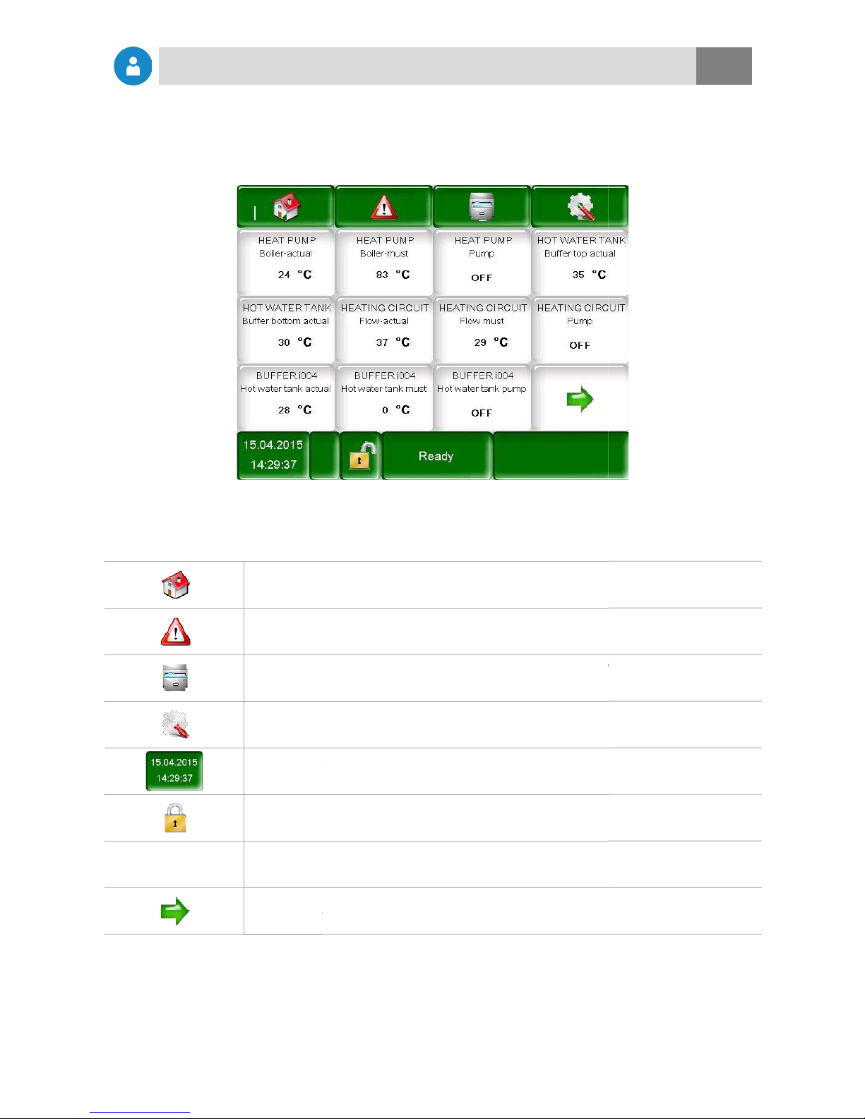
Determining main menu values
Adding main menu display values
Fault messages and warnings
................................
Module structure and navigation to the most important settings
................................
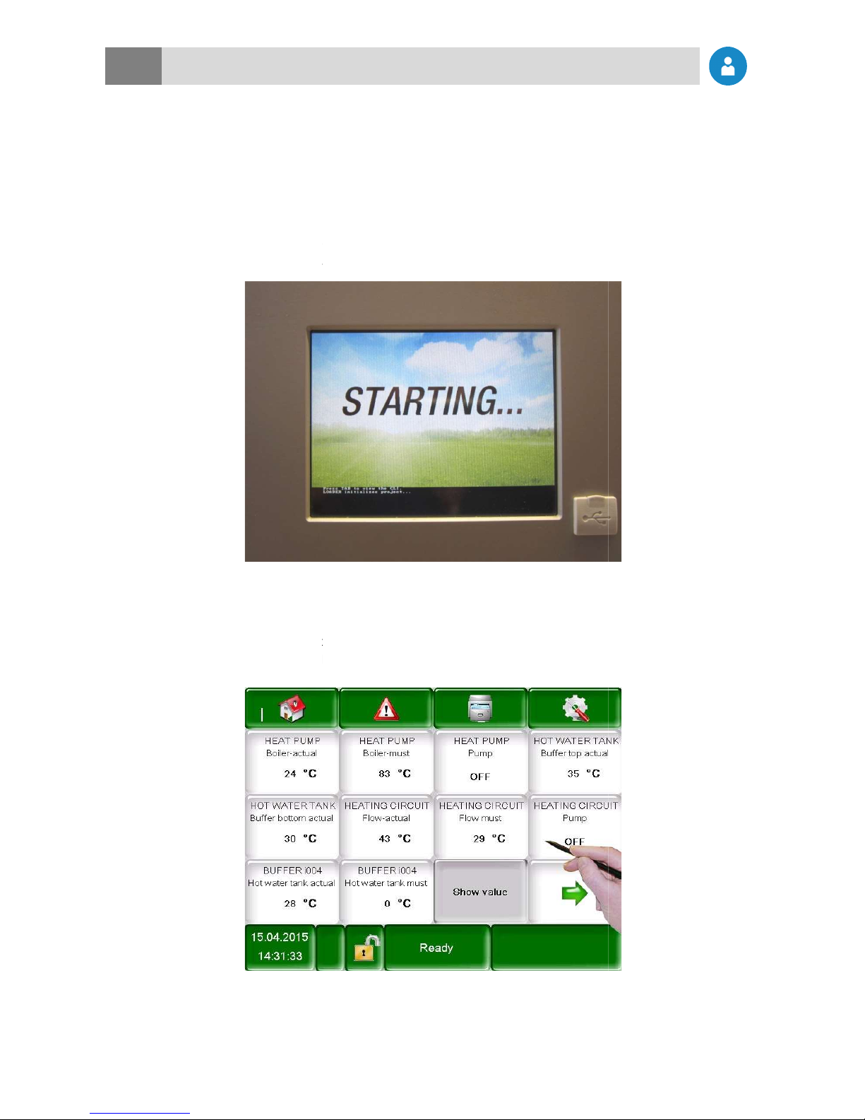
Switching on the heat pump
Switching off the heat pump
8.10.2 Hot water tank module
................................
................................
8.10.4 Heating circuit module
................................
................................
................................
8.10.7 Hydraulic compensator
................................
................................
................................
External requirement module
External additional boiler module
................................
8.11.1 Network configuration
................................
................................
................................
8.11.4 Information overview
................................
................................
8.11.6 E-Mail status report
................................
................................
................................
................................
................................
................................
................................
................................................................
................................
................................
................................
................................
................................
................................................................
................................
................................
................................
................................
Determining main menu values
................................................................
................................
Adding main menu display values
................................................................
................................
................................
................................
Fault messages and warnings
................................................................
................................
................................
................................
................................
Module structure and navigation to the most important settings
................................
................................
................................
................................
Switching on the heat pump
................................
................................
Switching off the heat pump
................................
................................
................................................................
................................
................................
................................
................................
................................
................................................................
................................
................................
................................
................................
................................
................................................................
................................
................................
................................................................
................................
................................
................................
................................
................................
................................................................
................................
................................
................................................................
................................
External requirement module
................................................................
................................
External additional boiler module
................................................................
................................
................................
................................
................................
................................
................................
................................
................................
................................
................................
................................
................................
................................
.............................
................................
................................
................................
..............................
................................
................................
................................
................................
................................
................................
................................
................................
.................................. 24
................................
................................
............................ 26
................................
................................
........................... 28
................................
................................ 28
................................
................................ 29
................................
................................
................................
................................
...................... 40
................................
................................
................................
................................
................................
................................
................................
................................
................................. 60
................................
....................... 61
................................
............................ 62
................................
................................
........................ 63
................................
............................... 64
................................
.......................... 66
................................
................................. 67
.............................
................................
..............................