Herz BW/WW User manual
Operating instructions
commotherm heat pump
for Brine- and water operation (BW, WW)

Introduction
2 Betriebsanleitung_commotherm_5_15_SW_WW_Touch_Englisch_V1.2
INTRODUCTION
Dear Customer!
Your heating system is powered by a HERZ commotherm heat pump and we are pleased to be able to count
you as one of our many satisfied owners of a HERZ system. The HERZ commotherm heat pump is the result
of years of experience and continuous improvement. Please remember that in order to be able to work
properly, a well-designed product also needs to be operated and maintained correctly. We definitely
recommend that you should read this documentation carefully while paying particular attention to the safety
instructions. Compliance with operating procedures is required for any claims made under the
manufacturer’s warranty. In the event of any faults or defects, please contact your heating specialist or the
HERZ Customer Service department.
Yours sincerely
HERZ – Energietechnik
Warranty / Guarantee (general information)
For Herz heat pumps we give a 3-year guarantee on the closed cooling circuit. The guarantee can also be
optionally extended to 5 years or a maximum of 15,000 operating hours, in each case via an appropriate
agreement. Storage tanks and HERZ solar collectors come with a 5-year warranty. We generally guarantee
freedom from defects of mobile objects purchased for a period of 2 years, to a maximum of 6,000 hours of
operation. For non-moving purchased items, the guarantee is generally for a period of 3 years to a maximum
for 9,000 hours of operation. Parts subject to wear are excluded from the warranty/guarantee. Furthermore,
claims under warranty will not be applicable if commissioning1 is not carried out by specialist personnel
authorised by HERZ or if hydraulic diagrams2, not recommended by HERZ are used.
Any claim to warranty services requires maintenance to be carried out on an annual basis by
specialist personnel authorised by HERZ.
The general warranty period will not be extended if work is carried out under warranty. In the event of a
warranty claim, the due dates for payments owed to us will not be deferred. We will only provide a guarantee
if all the payments owed to us for the product supplied have been made.
The warranty will be carried out at our discretion by repairing the item purchased or replacing any defective
parts, by exchanging the item or by reducing the price. Parts or goods replaced are to be returned to us at
our request free of charge. Wages and costs paid out in connection with installation and removal are to be
paid for by the purchaser. The same applies to all warranty services.
The Supplier shall under no circumstances be liable to the Customer, for any direct, indirect or consequential
costs incurred by the Customer for works carried out on HERZ equipment.
This document is the translation from the German original. The reproduction or copying, even of extracts,
may only be undertaken with the permission of the company HERZ©.
Subject to technical modifications,
Version 04/2015
1 Maintenance by the manufacturer
2 Recommended hydraulic diagrams can be found in the installation manual while hydraulic balancing will be carried out by the heating
contractor
Furthermore, the quality of the heating water must be in accordance with ÖNORM H 5195 (current version) or VDI 2035

Table of content
Betriebsanleitung_commotherm_5_15_SW_WW_Touch_Englisch_V1.2 3
TABLE OF CONTENT
page
1 Documentation notes ........................................................................................................ 5
1.1 General notes ...................................................................................................................................... 5
1.2 Symbols ............................................................................................................................................... 5
2 Safety notes ....................................................................................................................... 6
2.1 Warning notes ..................................................................................................................................... 6
2.2 Installation ........................................................................................................................................... 6
2.3 Operation and maintenance ............................................................................................................... 6
2.3.1 Operation ............................................................................................................................................... 7
2.3.2 Maintenance .......................................................................................................................................... 7
3 Information about the product ......................................................................................... 8
3.1 Intended use ........................................................................................................................................ 8
3.2 Type label ............................................................................................................................................. 8
3.3 Care and cleaning ............................................................................................................................... 9
3.4 Maintenance ......................................................................................................................................... 9
4 Plant overview ................................................................................................................... 10
5 Equipment functioning ..................................................................................................... 11
5.1 Refrigerant ........................................................................................................................................... 12
5.1.1 Characteristics of the refrigerant ........................................................................................................... 12
5.1.2 Measures when refrigerant escapes ..................................................................................................... 12
5.1.3 First Aid measures for contact with refrigerant ..................................................................................... 13
5.2 Safety devices ..................................................................................................................................... 13
5.2.1 Low pressure switch .............................................................................................................................. 13
5.2.2 High pressure switch ............................................................................................................................. 13
5.3 Operating conditions to be maintained ............................................................................................ 14
5.3.1 Permissible temperatures ..................................................................................................................... 15
5.3.2 Flow rate ................................................................................................................................................ 15
6 Operating conditions ........................................................................................................ 17
7 Temperature manager ....................................................................................................... 18
8 T-Control ............................................................................................................................ 19
8.1 Starting the system ............................................................................................................................. 19
8.2 Operation and handling ...................................................................................................................... 19
8.3 Main menu ............................................................................................................................................ 20
8.4 Symbols explanation .......................................................................................................................... 21
8.5 Code – entry ......................................................................................................................................... 22
8.6 Date and time ....................................................................................................................................... 23

1 Documentation notes
4 Betriebsanleitung_commotherm_5_15_SW_WW_Touch_Englisch_V1.2
page
8.7 Main menu values ............................................................................................................................... 24
8.7.1 Adding values ........................................................................................................................................ 24
8.7.2 Delete values ......................................................................................................................................... 25
8.8 Fault messages and warnings ........................................................................................................... 26
8.9 Modules overview ............................................................................................................................... 27
8.10 Module configuration .......................................................................................................................... 28
8.10.1 Heat pump ............................................................................................................................................. 29
8.10.2 Buffer ..................................................................................................................................................... 32
8.10.3 Hot water tank ....................................................................................................................................... 34
8.10.4 Heating circuit ........................................................................................................................................ 36
8.10.5 Time mode ............................................................................................................................................ 41
8.10.6 Solar ...................................................................................................................................................... 42
8.10.7 Hydraulic compensator module ............................................................................................................. 44
8.10.8 Net pump ............................................................................................................................................... 45
8.10.9 Zone valve ............................................................................................................................................. 46
8.10.10 External requirement ............................................................................................................................. 47
8.11 Menu settings ...................................................................................................................................... 49
8.11.1 Network configuration............................................................................................................................ 50
8.11.2 Modbus – settings ................................................................................................................................. 51
8.11.3 Screensaver .......................................................................................................................................... 52
8.11.4 Information overview ............................................................................................................................. 52
8.11.5 Mail sending .......................................................................................................................................... 53
8.11.6 Mail – status report ................................................................................................................................ 55
8.11.7 Server – settings ................................................................................................................................... 56
9 Fault reports and their corrections .................................................................................. 57
10 EC Declaration of conformity ........................................................................................... 62
11 Index................................................................................................................................... 63
Documentation notes
1
Betriebsanleitung_commotherm_5_15_SW_WW_Touch_Englisch_V1.2 5
1 DOCUMENTATION NOTES
1.1 General notes
Before commissioning, please read the documentation carefully and pay attention to the safety
instructions given in particular (see chapter 2). Please consult this manual if anything is unclear.
Make sure that you understand the instructions contained in this manual and that you are sufficiently
informed regarding the way in which the heat pump works. Should you have any queries at any time,
please do not hesitate to contact HERZ.
For safety reasons, the owner of the system must not make any changes to the construction or the state
of the system without consulting the manufacturer or his authorised representative.
All connections are to be checked before the commissioning of the system in order to make sure that
they are leak-tight.
A portable fire-extinguisher of the prescribed size is to be kept by the boiler room. (Please heed the
relevant national regulations).
Carry out maintenance regularly or use our Customer Service department. The maintenance jobs are
listed in chapter 3.4.
When carrying out maintenance on the system or opening the control unit, the power supply is to be
disconnected and the generally valid safety regulations are to be heeded.
It is also not permitted for objects which are not required for the purpose of operating or carrying out
maintenance on the system to be kept in the boiler room.
Should you have any queries, please call us on +43 / 3357 / 42840-840.
Initial commissioning must be carried out by the HERZ Customer Service department or an authorised
specialist (otherwise any warranty claim will not be applicable).
1.2 Symbols
The symbols which are fixed on the heat pump or which are listed in this documentation have the following
meaning:
Warning!
Information!
Dangerous electric tension!
Reference to other
documentation!
Hot surface!
Warning of hand injury!
Off limits to unauthorised
personnel!!
2 Safety notes
6 Betriebsanleitung_commotherm_5_15_SW_WW_Touch_Englisch_V1.2
2 SAFETY NOTES
2.1 Warning notes
Risk of injury and damage to property due to improper handling of the system.
However, adherence to guidelines for transportation, installation, operation and maintenance notices as well
as technical data (in the operating instructions, product documentation and on the equipment itself) which
are not specifically highlighted, is also vital to avoid breakdowns which may directly or indirectly cause major
personal or material damage.
General note
For reasons of clarity and possible permutations, this documentation does not contain all detailed information
and cannot take account of every conceivable operating or maintenance scenario. Should you require further
information or encounter specific problems, which are not handled in detail in the documentation supplied,
you can obtain the required information from your specialist dealer or direct from HERZ.
People (including children) who, because of their physical, sensory or mental capabilities or because of their
lack of experience or knowledge, are unable to use the equipment safely must not use this equipment unless
they are supervised or instructed by a responsible person.
Basic safety information
Due to its functionally limited electrical and mechanical characteristics with regard to usage,
operation and maintenance, if the equipment is not able to work according to its appropriate
use or improper interference occurs, it may cause serious health and material damage. It is
therefore conditional that the planning and implementation of all installations, transportation,
operation and maintenance will be carried out and supervised by responsible, qualified
persons.
When operating electrical systems, certain parts of those systems will always carry a
hazardous electrical voltage or be exposed to a mechanical load. Only appropriately
qualified personnel may carry out work on the system. They must be thoroughly familiar with
the content of this and all other manuals. In order for this system to function safely and
without any problems, transportation, storage, operation and maintenance must be carried
out properly and carefully. Instructions and information on the systems must also be
heeded.
2.2 Installation
In order to ensure that the system will function properly, the relevant standards and the manufacturer’s
installation instructions are to be heeded during the installation of the system!
Documents from the manufacturer relating to the heating devices and components used are available from
HERZ on request.
2.3 Operation and maintenance
In order for the system to be operated and maintained safely, it must be operated and
maintained properly by qualified personnel while heeding the warnings in this documentation
and the instructions on the systems.

Safety notes
2
Betriebsanleitung_commotherm_5_15_SW_WW_Touch_Englisch_V1.2 7
2.3.1 Operation
Covers which prevent contact with hot or rotating parts or which are required in order to
direct the flow of air correctly and thus ensure the effective functioning of the system must
not be opened during operation.
In the event of a fault or unusual operating conditions the system is to be switched off
immediately. Notify the HERZ Customer Service department immediately.
The generated system noise during operation does not present any danger to the operator´s
health.
2.3.2 Maintenance
Before starting to carry out any work on the system, but especially before opening covers
protecting live parts, the system is to be properly disconnected from the power supply.
Besides the main circuits, attention is also to be paid to any existing additional or auxiliary
circuits in the process.
The normal safety rules according to ÖNORM are:
Disconnect all poles and all sides!
Ensure that the system cannot be switched on again!
Check to ensure that no voltage is connected!
Earth and short-circuit!
Cover adjacent live parts and locate hazardous areas
These above-mentioned measures must not be reversed until the system has been fully
installed and maintenance has been completed.
In order to prevent any maintenance errors, if maintenance is not carried out properly, it is recommended to
be carried out regularly by authorised personnel or by the HERZ Customer Service department.
Spare parts must be obtained directly from the manufacturer or a distribution partner. The customer will not
be exposed to any health risks as a result of the noise generated by the machine.

3 Information about the product
8 Betriebsanleitung_commotherm_5_15_SW_WW_Touch_Englisch_V1.2
3 INFORMATION ABOUT THE PRODUCT
3.1 Intended use
The commotherm heat pump may be used only for
heating,
cooling and
hot water heating.
Any other use is considered improper.
In addition, the device may only be used within its technical application area! The
technical application is listed in the assembly instruction!
The intended use of the device includes also the attention of the following documents:
Operating, Installation and electrical documentation
Other applicable documents
Care and maintenance conditions
3.2 Type label
The type label is located on the back side of the heat pump. On the type label item number, production
number, heating power, application area are listed (see figure 3.1).
figure 3.1: Type label

Information about the product
3
Betriebsanleitung_commotherm_5_15_SW_WW_Touch_Englisch_V1.2 9
3.3 Care and cleaning
The care of the cover parts of the heat pump can be performed with a damp cloth and commercially-
available cleaning agents.
Do not use cleaning products that contain abrasives, acids and/or chlorine. These products could
destroy the surface of the cover parts and it is possible that damages can occur on the heat pump.
3.4 Maintenance
The refrigerant circuit of the heat pump requires no regular maintenance.
4 Plant overview
10 Betriebsanleitung_commotherm_5_15_SW_WW_Touch_Englisch_V1.2
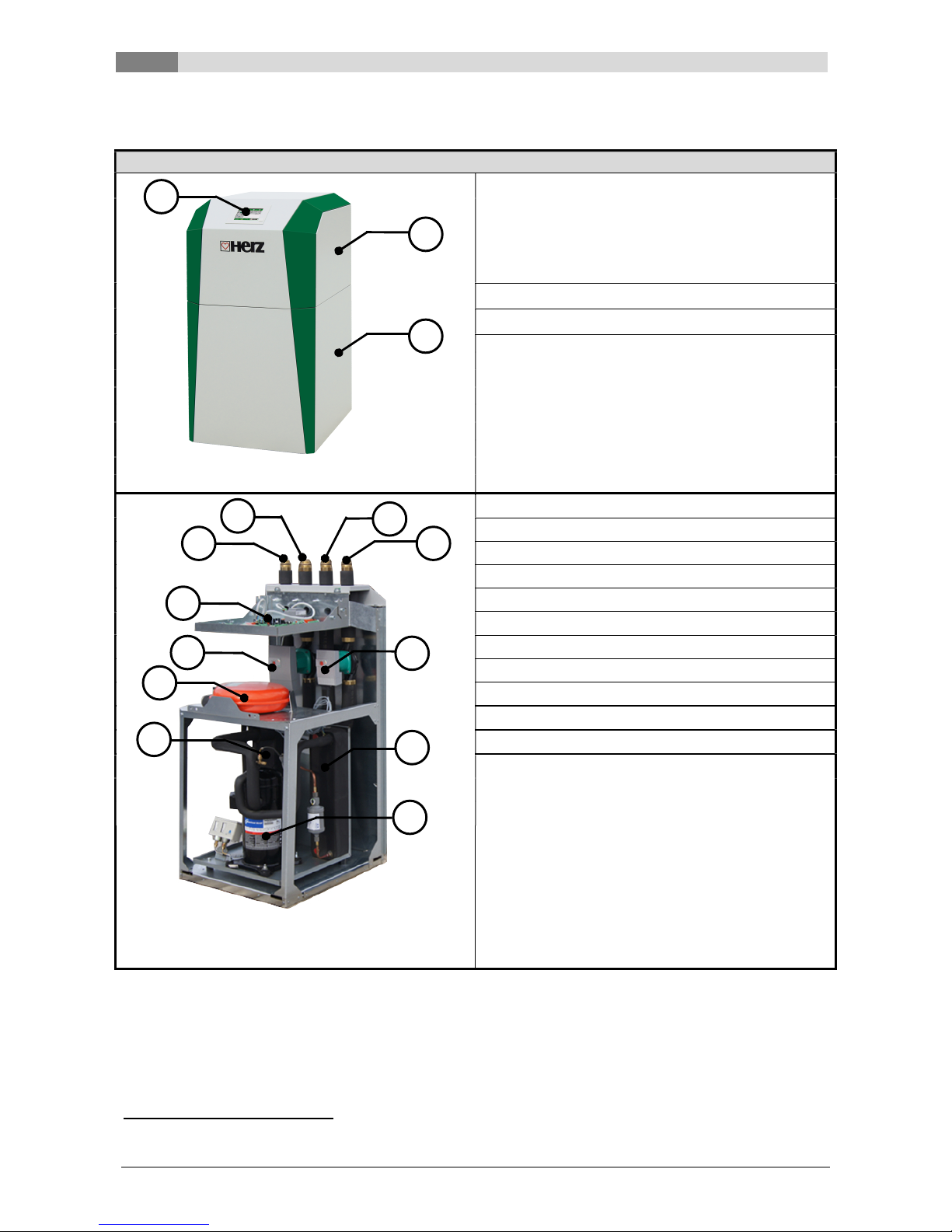
4 PLANT OVERVIEW
commotherm 5 – 15 BW/WW
3
1
Integrated control
The commotherm heat pump is equipped
with a user-friendly touch – display, which
can be used to control and operate the
system centrally. (The menu navigation for
the control can be seen in chapter 8).
2 Upper part of the casing
3 Lower part of the casing
1 Input source
2 Output source
3 Heating back flow
4 Heating flow
5 Operating part
6 Source pump
7 Brine side expansion vessel
8 Condensator pump (supply pump)
9 Compressor
10 Condensator
11 Evaporator
3 BW/WW Brine-Water/Water-Water
1
2
3
figure 4.2: System overview without casing
1
2
4
3
5
7
8
6
9
10
11
figure 4.1: System overview with casing
Equipment functioning
5
Betriebsanleitung_commotherm_5_15_SW_WW_Touch_Englisch_V1.2 11
5 EQUIPMENT FUNCTIONING
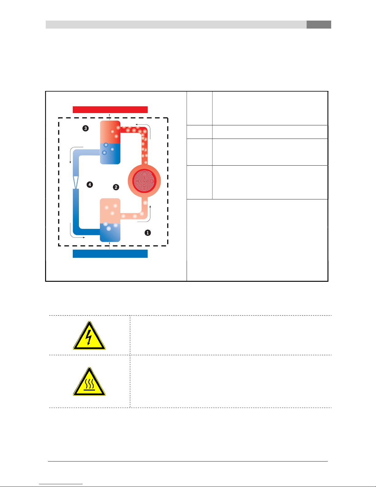
The core part of your HERZ heat pump is the cooling circuit. The main components are the evaporator (1),
compressor (2), condenser (3), expansion valve (4) and the refrigerant. At this point we should mention that
the handling of the refrigerant is described in chapter 5.1.
figure 5.1 shows the functioning of the heat pump. The refrigerant runs through 4 stages:
1
The fluid refrigerant is evaporated at low
pressure in the evaporator. This also takes
place at temperatures below 0° C. The
ground area, water or air serves as a
source of heat.
2 The compressor increases the pressure
and therefore raises the temperature.
3
The higher temperature is now used for
room heating or hot water preparation in
the condenser, and the hot refrigerant
gives off heat and becomes fluid again.
4
The high pressure is relieved in the
expansion valve and the coolant is
therefore released. The refrigerant can
once again take in heat from the ground
area, water or air.
The circuit is now closed and begins again
from the start.
The HERZ BW/WW heat pump is an “electrically-driven compression heat pump with the coolant, R407C”.
An electrically driven compressor compresses and feeds coolant through a pipe circuit consisting of copper
pipes, whereby pressure up to 30 bar may arise.
The device is under voltage. Removing the device casing as well as working
on the equipment parts may lead to serious physical harm.
The refrigerant supplied can affect surfaces of the equipment parts (pipes
and compressor) at temperatures of more than 100° C ( risk of burning).
Therefore:
work on equipment parts as well as electrical cabling may only be carried
out by qualified specialists.
HEATING CIRCUIT
HEAT SOURCE
Compressor
Evaporator
Condensator
Room heating / Hot water
Earth area / Water / Air
Expansion valve
cooling circuit
figure 5.1: functioning of the HERZ heat pump

5 Equipment functioning
12 Betriebsanleitung_commotherm_5_15_SW_WW_Touch_Englisch_V1.2
5.1 Refrigerant
Generally, what is understood by a refrigerant is a working material for heat pumps or cooling machines. The
refrigerant circulates in a closed system and is also subject to various changes in condition (see figure 5.1).
The HERZ heat pump works with the refrigerant, R407C, which consists of the following components:
1,1,1,2-tetrafluoroethan (R134a)
50% - pentafluoroethane (R125)
50% - difluoromethane (R32)
5.1.1 Characteristics of the refrigerant
According to ÖNORM EN378-1 refrigerants are divided up into groups with regard to health and safety:
Classification according to flammability
Classification according to toxicity
Group 1: No flame propagation Group A: Lower toxicity
Group 2: Lower flammability Group B: Higher toxicity
Group 3: Greater flammability
Table 5.1 shows the position of the refrigerant, R410A, used in safety group A1.
Table 5.1: safety group for the coolant, R410A, used
Safety group
Greater flammability A3 B3
Lower flammability A2 B2
No flame propagation A1 B1
Lower toxicity Higher toxicity
Other characteristics are:
Ozone reduction potential: 0
Boiling temperature: - 48,5 °C
Temperature operating range: -25°C to 32°C
5.1.2 Measures when refrigerant escapes
If refrigerant escapes, fast evaporation of the fluid may cause frostbite. Steam is also heavier than air, which
may lead to suffocation due to displacement of oxygen in the air. If an escape of refrigerant is noticed (it is
heard to escape, icing over of the exit point), the following measures should be taken:
Ensure there is adequate ventilation.
Close and seal the door to the room where the equipment is located.
Notify HERZ service or customer service.
People must leave the room where the equipment is located straight away.
Consult the doctor or veterinarian if people or animals were exposed to an increased dose for a long
period.
Switch off the power immediately.
In the event of fire, any type of fire extinguisher may be used.
There is no risk of the R410A refrigerant escaping if the HERZ heat pump is
used correctly. If there is an escape of refrigerant due to improper use, there
is a risk of suffocation (air displacement) and frostbite (exit points may
become extremely cold). In chapter 5.1.3 First Aid measures are also
described for contact with coolants.
Equipment functioning
5
Betriebsanleitung_commotherm_5_15_SW_WW_Touch_Englisch_V1.2 13
5.1.3 First Aid measures for contact with refrigerant
General Tips
In the event of unconsciousness, place carefully on the side and seek medical
advice
Never allow an unconscious person to take in anything by mouth
With irregular breathing or if breathing stops, try artificial respiration. If complaints
persist, seek medical advice
Inhalation
Take the person out of the contaminated area
Respiration with breathing apparatus or oxygen supply
In the event of difficulties with breathing or nerve problems, seek medical advice
Go into the fresh air
Contact with the
Open the eyelids wide to vaporise the agent
eyes
Rinse the eyes out with flowing water for a few minutes, opening the eyelids wide
In the event of continuing sore eyes, seek medical advice
Contact with the
Vaporise the agent
skin
Rinse with lukewarm water
If soreness continues or the skin is red, seek medical advice
Remove soiled or soaked clothing immediately
Never remove refrigerant, let it escape or add additional refrigerant yourself.
This is a risk to humans, animals, the environment and the device itself.
5.2 Safety devices
The pressures in the commotherm heat pump should remain within a define range. To ensure this, so-called
pressure switches are built in. These serve on the one hand as a safety device, and on the other hand to
ensure that the heat pump works in the defined range. The pressure switches are designed as chamber
pressure switches, i.e. the set, adjusted pressures cannot be reset by unauthorised persons. The pressure
switches are also used as low or high pressure switches. These devices are briefly described below.
5.2.1 Low pressure switch
The low pressure switch turns off the compressor at an operating pressure of < 1 bar and therefore protects
this at low pressure (low pressure may be caused by a lack of refrigerant, for example).
5.2.2 High pressure switch
High pressure switches also serve to switch off the compressor in an emergency. In contrast with low
pressure switches, however, this turns off the compressor at a higher pressure. In the event of the BW/WW
heat pump this occurs at pressures of > 28 bar.

5 Equipment functioning
14 Betriebsanleitung_commotherm_5_15_SW_WW_Touch_Englisch_V1.2
5.3 Operating conditions to be maintained
Some important operating conditions are described below, which must be adhered to.

Equipment functioning
5
Betriebsanleitung_commotherm_5_15_SW_WW_Touch_Englisch_V1.2 15
Table 5.2 also gives a summary on avoiding faults, if these conditions are not adhered to.
5.3.1 Permissible temperatures
Flow temperature
The heat pump should be operated with a maximum flow temperature of 58° C. If a flow temperature of more
than 58° C is selected, the heat pump works inefficiently. The compressor is also very greatly overloaded
and the equipment will keep malfunctioning.
In general, the flow temperature should actually be adapted to the actual operating temperatures and be set
as low as possible.
Brine temperature
The brine temperature should not be lesser than -6°C. If the temperature is lesser, the device works
inefficient and there is danger of freezing of the device.
5.3.2 Flow rate
No flow rate for heating equipment
If there is no flow rate in the heating equipment, the system will be extremely overloaded until release of the
safety device, in this case the high pressure switch. The water flow rate and system pressure should
therefore be checked.
No flow rate in the brine system
If there is no brine side flow rate, again the system will be extremely overloaded until release of the low
pressure switch. A freezing of the system and the heat exchanger inside the device may also occur until the
heat exchanger bursts and then there is a leak of refrigerant. In the worst case, the device is damaged and
will have to be replaced. The solution here again, is to check the water flow rate and the system pressure as
well as checking the frost safety (at least -15° C).
No ground water flow rate (only at W/W-devices)
Analogous to the missing flow rate in the brine system the device will be extremely overloaded until release
of the low pressure switch. Moreover, a freezing of the system and the external heat exchanger is possible
again. A compensation takes place by a control of the water flow, of the system pressure and the
groundwater conveyor system, a cleaning of the filters and an annual maintenance of the under water pump.

5 Equipment functioning
16 Betriebsanleitung_commotherm_5_15_SW_WW_Touch_Englisch_V1.2
Table 5.2: Summary of the operating conditions to be maintained
Fault source Possible consequences Measures to avoid faults
Flow temperature
> 58°C
Device works inefficiently
Adapt operating temperatures to
the actual requirements and set as
low as possible
Device is constantly malfunctioning
Compressor is heavily overloaded
Brine temperature
< -6°C
Device works inefficiently
Control the brine flow
Danger of freezing of the device
Possibly air in the system
System pressure too low
No flow rate for
heating equipment
The system will be extremely
overloaded until the safety device is
released (high pressure switch)
With new systems, daily checking
of the water flow rate is required
(thereafter annually).
No flow rate for
brine equipment
The system will be extremely
overloaded until the safety device is
released (low pressure switch)
With new systems, daily checking
of the water flow rate is required
(thereafter annually).
Freezing of the system and the heat
exchanger inside the device may
also occur until the heat exchanger
bursts and then there is a leak of
coolant.
Annual check of frost safety (at
least -15
℃
)
The system is damaged and will
have to be replaced.
No ground water
flow rate (only at
W/W-devices)
The system will be extremely
overloaded until the safety device is
released (low pressure switch)
At new installation the flow and
system pressure should be
controlled every day (thereafter
annually)
Freezing of the device and the
external heat exchanger
Cleaning of the filters
Control of the groundwater
conveyor system
Annual maintenance of the under
water pump

Operating conditions
6
Betriebsanleitung_commotherm_5_15_SW_WW_Touch_Englisch_V1.2 17
6 OPERATING
CONDITIONS
Ready
There are essentially two versions to be
differentiated here, for which the heat pump may
be in the operating condition "ready”:
In the “OFF” mode the heat pump does not
work and is ready to start.
If the heat pump is in “heating operation” or
“cooling operation” mode but there is no
request from the user, the operating condition
"ready" also appears
Wait
This condition serves as compression protection.
If the compressor is switched off and switched on
again straight afterwards, the compressor only
starts after minimal downtime, which may be, for
example, 10 minutes. The “wait” condition is then
displayed.
The compressor may also only be started 6 times
per hour. If the compressor is started more
frequently, it also remains in “wait” operating
condition.
Pump flow
In this condition, the source and condenser pump
start up and run for a pre-set time. This serves to
build up circulation in both circuits.
Compressor
In this condition, the heat pump run and heat or
cooling consumer sends a request to the heat
pump.
Stop
In this condition, the heat pump is switched off but
the source and condenser pump are still running
in so-called pump stoppage to transport any
residual heat / cold to the heat consumer. The
pump stoppage continues according to the fixed
set pump stopping time.
Error
A serious fault has occurred. The heat pump and
all outputs are switched off too.
Cooling mode
This condition indicates that the heat pump is
cooling, i.e. the process is reversed and the
system is taking in heat and diverts this to the
source, for example.
Min. temp.
The heat pump changes in this condition as soon
as the source has reached a minimum
temperature. The source pump is also switched
on which brings about circulation and a
regeneration of the equipment in the brine circuit.
Max. temp. Residual heat
This condition is achieved if the flow temperature
of the heat pump is greater than the set maximum
temperature (usually 58° C). To lower the flow
temperature the circulation pump is switched on.
This runs as long as the maximum temperature is
not reached.
Residual heat
The compressor is switched off here and residual
heat is supplied to heat consumers.
Ext. Stop
The input “external stop” has responded and the
heat pump is switched off. The heat pump only
starts up again if the input “external stop” is no
longer responding. This input can respond, for
example, through phase limit switching by the
energy supply company.
7 Temperature manager
18 Betriebsanleitung_commotherm_5_15_SW_WW_Touch_Englisch_V1.2
7 TEMPERATURE MANAGER
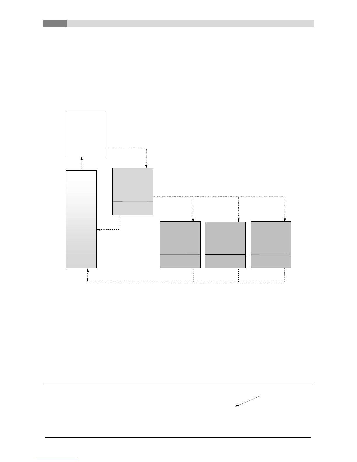
The heat demand of the individual modules (boiler, hot water tank, heating circuit, solar, etc.) is controlled by
the temperature manager. The below-mentioned scheme (see figure 7.1) explains the functionality of the
temperature manager. A module contains of an in- and output. Every module sends a required demand
temperature to the temperature manager. The sent required demand temperature is a sum of an internal
calculated temperature demand + set up increase. The heat supplier (= heat generator respectively heat
pump/hot water tank), which receives the different module demand temperatures from the temperature
manager, must supply the required temperature demand to the different modules. The temperature manager
calculates the maximum demand temperature of all modules.
Example:
Heat supplier = heat pump
Module 1 & 2 = heating circuit 1 & 2
Module 3 = hot water tank
Module 4 = buffer
Heating circuit 1 Heating circuit 2 Hot water tank Buffer
Calculated required temperature [°C]
40 30 55 48
Temperature increase [°C]
5 3 0 2
Required temperature of the
modules [°C]
45 33 55 50
Maximum temperature requirement
55
HEAT PUMP
(Heat supplier)
B
UFFER
(Module 4)
HEATING
CIRCUIT 1
(Module 1)
HEATING
CIRCUIT 2
(Module 2)
HOT WATER
TANK
(Module 3)
Temp. requirement
+ increase
Temp. requirement
+ increase
Temp. requirement
+ increase
Temp. requirement
+ increase
TEMPERATUR
E
MANAGER
figure 7.1: Temperature manager (simplified scheama – example)

T-Control
8
Betriebsanleitung_commotherm_5_15_SW_WW_Touch_Englisch_V1.2 19
8 T-CONTROL
The handling and menu navigation are described in this chapter. Every single T-CONTROL parameter is
explained in chapter 8.10 (page 28).
8.1 Starting the system
To switch on the display, the following condition must be fulfilled:
The heat pump must be connected to the power supply
If this condition is fulfilled, the starting process of the display, which takes 1-2 minutes, starts (see figure 8.1).
figure 8.1: Starting process of the display
8.2 Operation and handling
The touch panel is a touch-sensitive screen and control unit. By touching the screen you can change
released values or move to other pages. The screen navigation and input can be done with finger, pen,
pencil, etc.
figure 8.2: Screen navigation with finger or pen
8 T-Control
20 Betriebsanleitung_commotherm_5_15_SW_WW_Touch_Englisch_V1.2
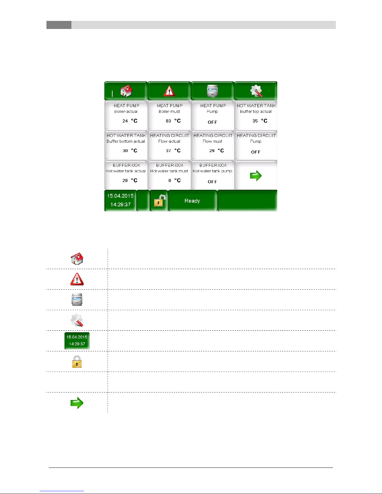
8.3 Main menu
After start up figure 8.3 will appear. In the centre of the screen important values according the boiler, buffer,
hot water tank, heating circuit and so on are shown. The shown values can be adapted individually (see
chapter 8.7.1).
figure 8.3: Main menu
If the following symbol is pressed
the main menu will be displayed.
(see figure 8.3)
fault messages (warnings & alarms) will be displayed.
(see figure 8.14)
the individual modules (heat pump, hot water tank, buffer, heating circuit, solar) will
be displayed.
(see figure 8.15)
the menu settings (network configuration, E-Mail, screen saver) will be displayed.
(see figure 8.19, visible only with code!)
the date & time can be set up.
(see figure 8.6, visible only with code!)
the code input screen will be shown.
(see figure 8.4)
Ready in general the field is used to display the operating conditions (see chapter 6).
more important values will be shown on the second page.
Table of contents
Other Herz Heat Pump manuals


Popular Heat Pump manuals by other brands

BWT
BWT SHP2.5 ON/OFF Installation and operating instructions

Emerson
Emerson Copeland EazyCool ZX Series manual

ClimateMaster
ClimateMaster TRM Series Installation, operation & maintenance instructions

Hitachi
Hitachi YUTAKI S COMBI Series instruction manual

Atlantic
Atlantic alfea extensa + Installation and operating manual

Heatmaster
Heatmaster R-22 Series owner's manual

Daikin
Daikin Altherma ERYQ005ABV3 installation manual

Igloo
Igloo MultiTherma mobile user manual

Carrier
Carrier CPCRKHTR003A00 installation instructions

Eubank
Eubank TH Series Installation & operation manual

Gree
Gree GWH09MA-A3DNA3A Installation, service & troubleshooting

Dimplex
Dimplex SI 5MER Installation and operating instructions


