HEUTE Neptun SC1 User manual
Operating Manual EN
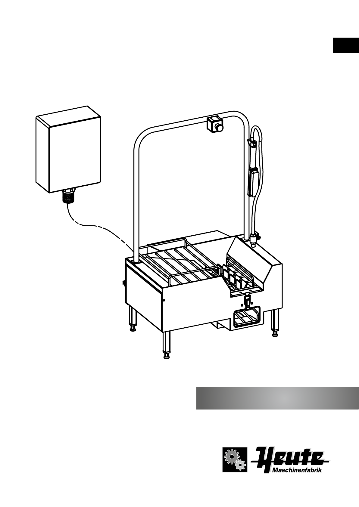
Neptun SC1
2
IMPORTANT – READ FIRST
Only put the machine into operation once you have read and
understood the operating manual. We shall be happy to answer
any questions you may have.
HEUTE® sole cleaning machine Neptun SC1 cleans and disinfects
dirty soles of working and safety shoes and boots. By means of an
integrated hand brush bootlegs and plastic trousers can be
cleaned effective.
HEUTE® sole cleaning machines are built and tested in accordance
with the latest safety regulations. The faultless functionality
and operational assurance of the device can only be guaranteed
if the generally applicable safety precautions and device-specic
safety information in this operating manual are observed during use.
The guarantee is not valid in relation to damages caused by a failure
to observe this operating manual. The manufacturer assumes no lia-
bility for personal injury or damage to property arising as a result of
this. In the event of problems please contact our service department
immediately.
Intended use
HEUTE® sole cleaning machine Neptun SC1 is used to clean closed
shoes and boots outside by means of an electrical driven brush and
hand brush as well.
Other use is not permitted! Only use the spare parts approved for
use with the machines by the manufactuer. Operation is only permis-
sible in closed rooms whilst observing the specications mentioned
in the "Safety instructions" section.
Use in potentially explosive environment is not permitted.
Foreseeable misuse
The sole cleaning machine is not suitable for use as follows:
- Cleaning and care of human body parts and objects that are not
parts of a shoe.
- Use as a tool for working on surface nishes
- Use with the addition of corrosive uids
Safety instructions
Read this operating manual carefully and follow our
advices for starting and for use.
The machine must not be changed or modied
because this can lead to risks such as a short circuit,
electric shock, re. Maintenance and repairs must
be carried out exclusively by authorised persons with
the use of original parts.
The use of non-original spare parts or the implemen-
tation of unauthorised modications to the machine
will result in cancellation of the declaration of
conformity issued by the manufacturer/distributor
and sign as well.
Use the machine only in closed rooms.
Operation is only permissible at ambient
temperatures between 0° C and 40° C.
The machine is not suitable for permanent operation.
It is essential to consider the time of duration (KB)
mentioned under section technical data - see page 14.
Do not continue to use the machine if the cleaning
brushes are worn. This can result in damaging the
shoes. The brushes must be replaced by a qualied
person.
The design complies with protection class IP55. The
voltage supply is 3-phase 400 V + grounding, power
0,18 kW. Observe the specic data provided on the
manufacturer's type plate!
During use, the motor can heat up to temperatures of
up to 90° C. Do not touch the motor without safety
gloves.
Use by children, in particular when unattended, must
be excluded.
Ensure that any contact between (household) animals
and the machine is excluded.
For safety reasons please pay attention that during
use of the rolling brush no laces and straps will touch
the ground.
These can be catched by the rolling brush, which
could cause injuries and damage of the shoes/boots.
Always disconnect the mains plug prior to cleaning,
service and repair work. Do not continue to use the
machine if the machine or the control cabinet with
cabling, the water pipe and water drain are damaged.
Ensure that the installation is at ground level.
Enter and use the machine only with closed shoes/
boots appropriate for wet cleaning.
Slip danger - pay attention to slippery ground in front
of and besides the machine caused by splashing
water.
Do not touch rotating brush.
Never drink the water out off the machine or the
detergent liquid out of the container (option).
Excessive application pressure during use of the
brush can lead to damage of shoes/boots!
Stop using the machine in case that brush stops
and potential foreign objects cause malfunction.
The operator is responsible for all personal injury and
damage to property that arises due to unintended
use, faulty machine connections and/or operating
errors.
When in commercial facilities observe the safety
ordinance applicable on site as well as the acci-
dent prevention regulations issued by the union of
professional associations for electrical systems and
equipment.
3
Welcome
Dear Customer, we would like to thank you for purchasing one of
our HEUTE industrial sole cleaning machines. You have purchased
a quality product, which – if used correctly – will provide many years
of satisfaction.
This operating manual is a constituent of the machine. It contains
important information on commissioning, operation and mainte-
nance. Please store this operating manual for future reference!
Scope of delivery
Sole cleaning machine with integrated hand brush, control cabinet,
operating manual.
Declaration of conformity
The manufacturer herewith conrms that the following machine
of type Neptun SC1 complies with the directives listed below:
- EC Machinery Directive (2006/42/EC)
- EC EMV Directive (2004/108/EC)
Technical specications
- DIN EN 60335-1 (DIN VDE 0700-1):2014-11
- DIN EN 60335-2-82 (DIN VDE 0700-82):2009-02
- DIN EN 55014-1 (DIN VDE 0875-14-1):2012-05
- DIN EN 55014-2 (DIN VDE 0875-14-2):2009-06
- DIN EN 61000-3-2 (DIN VDE 0838-2):2015-03
- DIN 61000-3-3 (DIN VDE 0838-3):2014-03
- DIN 61000-6-2 (DIN VDE 0839-6-2):2011-06
- DIN 61000-6-3 (DIN VDE 0839-6-3):2012-11
Authorized representative Steffen Moersch,
contact details (see address of manufacturer)
Christian Löwe, Managing director
Maschinenfabrik HEUTE GmbH & Co. KG
Environmental protection
Disposal of transport packaging
The packaging materials in which your machine is supplied are
environmentally friendly and recyclable. Please help by disposing of
the packaging in an environmentally friendly manner. The packaging
must not be given to children to play with. There is a risk of
suffocation due to the folding box and plastic lm.
Disposal of the product
Old devices that are no longer in use are not worthless waste.
Valuable raw materials can be recovered through environmentally
friendly disposal. Please inform yourself of the current disposal
methods by contacting the person responsible within your company
or your local authority
Table on contents
Important – read rst 2
Intended use 2
Foreseeable misuse 2
Safety instructions 2
Welcome 3
Scope of supply 3
Declaration of Conformity 3
Environmental protection 3
Overview 4
Installation and commissioning 6
General information 6
Transport and assembly 6
Water connection 6
Waste water connection 6
Electrical connection 6
Precaution while commissioning 6
Operation 7
How to clean 7
Adjustment of water quantity - access 7
Adjustment of water quantity 7
Use of sole cleaning function 7
Use of hand brush 8
Non-usage for longer time 8
Service and maintenance 8
Control 8
Cleaning 8
Maintenance 8
Recommended service intervals 9
Cleaning of surfaces 9
Cleaning and access to heavy waste-strainer 9
Cleaning of roller brush 9
Change of roller brush 9
Disassembling of brush axle 10
Access to gear motor 10
Dosing system - access 11
Dosing system 11
Dosing system - activation 12
Dosing system - rinsing 12
Trouble shooting 13
Technical data 14
Wiring diagrams 15
Parts drawing 17
EN
4
633 mm
300 ± 15 mm
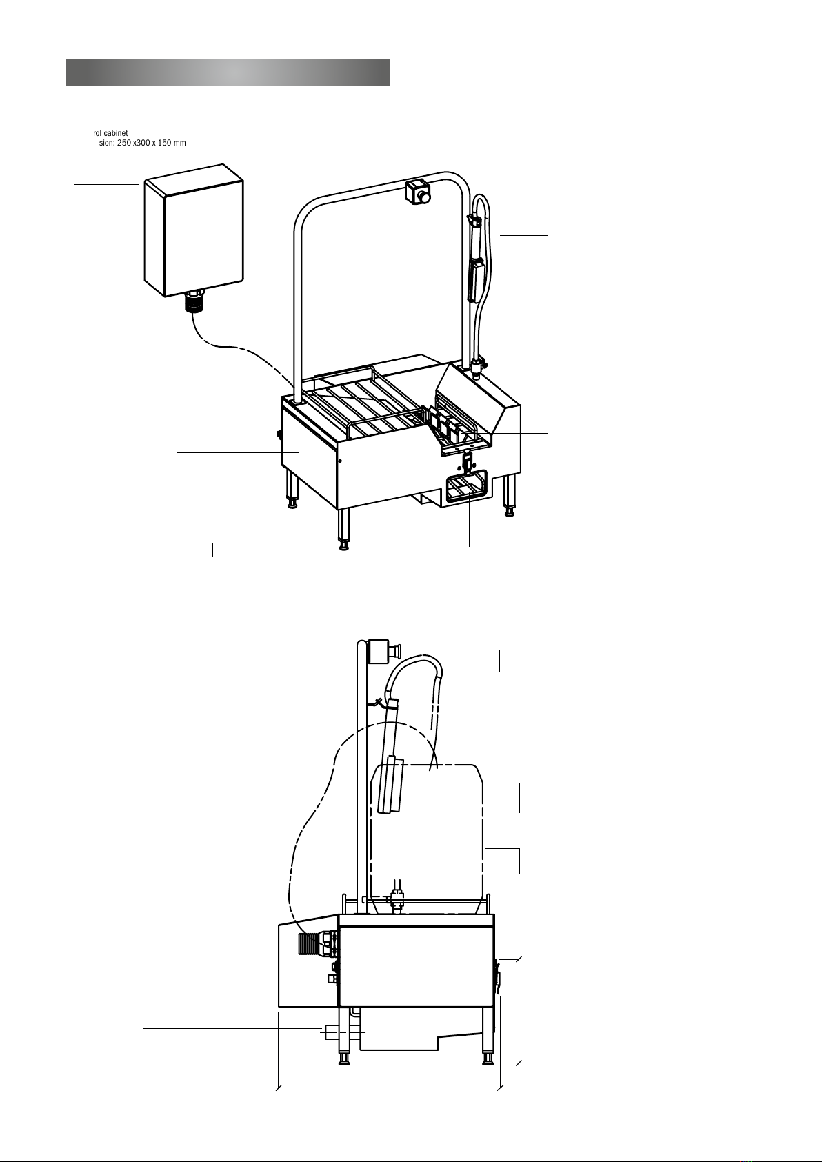
Control cabinet
Dimension: 250 x300 x 150 mm
Power supply 400 V,
3-phase + grounding
50Hz P=0,18kW
Water outlet with siphon
ø 38 mm with heavy waste strainer
and opening for inspection
Hand brush with exible PVC hose
and ball valve 1/2"
hand brush with exible PVC hose
and ball valve 1/2"
Detergent canister
(not belonging to the machine)
Push button
Brush ø 150 mm, can be easily
removed without any tool for cleaning
PVC hose to protect
electrical cables
(length 2 m)
Access to dosing
system of detergent /
disinfectant
Adjustable feet ABS
Opening for cleaning of shoe/
boot tip and heels
Overview

5
EN
229 mm
755 mm
100 mm
92 ± 15 mm
1215 ± 15 mm
245 ± 15 mm
Water inlet 1/2" male,
dosing system
Inlet for transparent
silicone hose / dosing system
platform to store
detergent canister
grid, when closed lockable
by bracket clamping
nylon roller brush
ø 150 mm, length 330 mm
Inlet for PVC hose
(to protect electrical cables)
Water connection for hand brush
6
Installation and commissioning
General information
Please follow below mentioned advices to protect the stainless
steel housing of the sole cleaning machine during storing, before
installation, commissioning and use.
- Protect the machine against environmental inuences like rain,
sunshine and frost. Use the machine only in closed rooms.
- To avoid contact corrosion (e.g. steel spanes, tools used for steel
treatment) the surface of the machine must not be in touch with
other kind of steels
Transport and assembly
Weight of the machine is abt. 50 kg. Due to the heaviness transpor-
tation and unpacking should be done by 2 workers using suitable
means of transport.
Only use the machine in closed rooms. When choosing the place of
installation please consider the necessary space 755 x 640 mm,
availability of waterinlet and -outlet, as well as power supply (more
details see section Installation and commissioning). Control cabi-
net has to be xed at suitable place on the wall. The ground must be
level and slip protected. To ensure stability level out any uneven oor
areas by adjusting the feet under help of a spirit level.
Water connection
- Inlet dia. 1/2"
- Advised operating pressure: 3 bar
- Maximum operating pressure: 6 bar
- Operating temperature between 30 °C and 50 °C
(water temperatur more than 60 °C will damage the brush)
- Water ow rate: abt. 4 l/min with 3 bar
(adjustable valve at the machine)
The machine is not equipped with an upstreamed return valve
and water ltre. If necessary return valve and water ltre have to
be installed before the unit. The requested water quantity can be
indiviually adjusted – see sector Operation > adjustment of water
quantity.
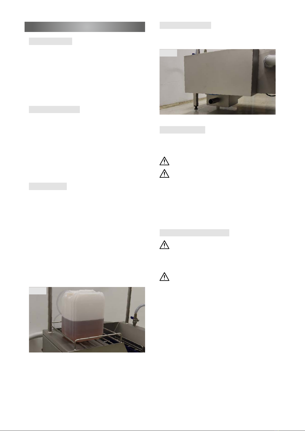
Put the detergent canister (not belonging to the machine) at suitable
place (Fig. 1).
Electrical connection
- 3-phase 400 V + grounding, power 0,18 kW
- Connection to the clamps in the control cabinet
(see sector "Technical data" > conguration of clamps
Take care that available voltage in your country is
corresponding to machine's voltage!
Machine's power supply must be electrically protected
against indirect contacts!
- High sensitive difference power protection device max. 30 mA.
- This protection must be provided by the house installation and
is not supplied with the machine.
- The control cabinet should be mounted approx. 1,2 m above oor
level.
- Turn-on and check rotating direction of the brush.
Precaution while commissioning
Never remove or block the contact switches on the housing,
which are active when the grid is closed/down. When open-
ing the grid during operation these will automatically turn off
the water and power supply and will stop rotation
of the brush.
The installation works for the water supply could cause
soiling which can block the pipes, nozzles, dosing device
and could damage the solenoid valve. It is important that
the machine is free of metal and plastic parts, before it is
connected to the electric circuit.
Fig. 2
Fig. 1
Waste water connection
- Outlet ø 38 mm (Fig .2)
- Provided with an access ap at the piping
7
Operation
How to clean
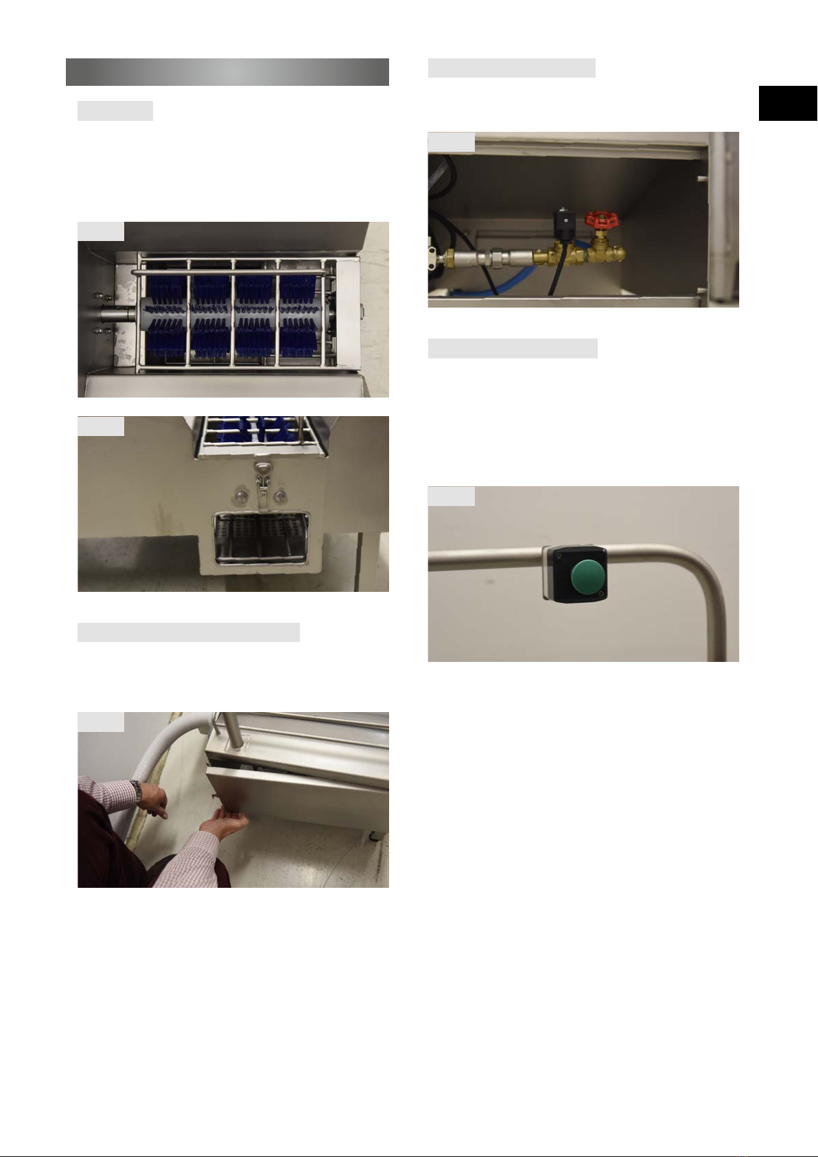
- Cleaning of shoes/boots with horizontal roller brush (Fig. 3)
- Cleaning of shoe tip by means of separate cleaning opening
underneath of horizontal roller brush – EasyClean function (Fig. 4)
- Supply of water and detergents, dosage by mixture in the dosing
system
Use of sole cleaning function
Start the sole cleaning function by pressing the push button (Fig. 7)
causing:
- Rotation of roller brush will start.
- Solenoid valve of the dosing system opens and starts spraying
water and detergents on the rotating roller brush.
- Release push button to stop the sole cleaning process.
EN
Fig. 3
Fig. 4
Fig. 7
Adjustment of water quantity – access
The handwheel (valve) for adjusting the water quantity is located on
the side. Remove the cover by opening the bracket clamping – no
tools needed (Fig. 5)
Adjustment of water quantity
The requested water quantity is adjustable by the valve (Fig. 6).
The medium position allows a water ow of about 4 litres/minute.
Fig. 6
Fig. 5

8
Use of hand brush
Bootlegs and plastic pans can be easily and effectively cleaned with
the hand brush installed at right hand side (Fig. 8). Move the handle
of the valve to adjust water quantity (Fig. 9). Medium opening allows
a water ow of abt. 6 litres/minute.
Non usage for longer time
If you know that the machine will not be used for longer time (e.g.
annual holidays), we advise to rinse the dosing system through in
advance to avoid blockage of dosing system.
Fig. 8
Fig. 9
Service and maintenance
Service and maintenance should be carried out only by customer
service technicians. To secure optimal functioning of the sole clean-
ing machine, it should be contolled in regularly intervalls. HEUTE sole
cleaning machines are service reduced and reliable. However, there
are some components which will wear after long period of time and/
or reduce the cleaning result.
Unplug the power supply at the control cabinet prior to all
repairs.
Before any action stop water supply.
Drain the transparent silicone hose of the dosing system.
Rinse through the dosing system to remove residues.
In case of unintended opening of the grid the roller brush
stops automatically and the solenoid valve will close the
water supply.
Control
The machine should be controlled regularly. Take care if components
are damaged or worn and if the machine achieves the necessary
cleaning result. Foreign objects may not be nearby the roller brush.
Cleaning
The intervals of cleaning depends on local circumstances. The more
dirt occurs the shorter should be the cleaning intervals. Don't forget
to clean the dosing system regularly.
The mixture of used disinfectant and detergent should correspond
with local regulations of hygiene and cleanness.
Maintenance
Neptun SC1 sole cleaning machine is service reduced and reliable.
However, there are some components which will wear after long
period of time and/or reduce the cleaning result, e.g. roller brushes.
Overused roller brushes are visible by bent down and too softy
bristles.
Suitable spare parts are available from your local dealer or from
manufacturer.
Advices to change spare parts please read more in section "Service
and maintenance".

9
EN
Recommended service intervals
Below mentioned intervals are based on our experience. However,
any single case could vary from each other. That is the reason why
you have to adapt the intervals according to your own experience.
Change of roller brush
1. Lift up the grid to have access to the roller brush. It can be
removed without any special tool (Fig. 10).
2. Roller brush: Pull it at the front side. The gear of roller brush
happens by a pin located at the motor side (Fig. 11).
3. When insert the roller brush pay attention that the pin is in
the right position and the brush ts properly.
Fig. 11
Fig. 10
Service
Interval
Control once a week
Cleaning of surfaces once a week
Cleaning of
heavy waste strainer once a week
Cleaning of brushes once a month
Cleaning of dosing system once a month, strictly when
changing the medium
Change of roller brush every 5-7 years,
earlier when worn
Cleaning surfaces
The surface is made of stainless steel type 304.
Cleaning should be done with intensive water rinsing.
Avoid following:
- contact with carbon steel
- use of steel sponge, grinding powder
- use of chlorine products and bleaching agent
Cleaning and access to heavy waste strainer
Remove roller brush rst - see section "Service and maintenance"
> Change of roller brush.
Lift up the heavy waste strainer to remove (Fig. 12). Insertion in
reversed order.
Cleaning of roller brush
Cleaning of roller brush should be done by intensive water rinsing
or by soaking in suitable detergent. Never use chlorine products and
bleaching agent. Use of high pressure cleaner is strictly forbidden.
Overused roller brushes are visible by bent down and too softy
bristles.
Fig. 12

10
Disassembling of brush axle
1. Remove roller brush (see section "Service and maintenance" >
Change of roller brush)
2. Remove inbus screw placed at the long side in front of the brush
with suitable tool (Fig. 13)
3. Remove snap ring located at front side of the brush with suitable
tool and pull off the distance washer (Fig. 14)
4. Now the brush can be pulled off the axle (Fig. 15)
5. When assembling put the pin in the center position of the brush,
x the inbus srew, insert distance washer (ø 30 mm) and snap
ring.
Fig. 15
Fig. 16
Fig. 14
Access to the gear motor
The cover at the rear is not xed.
Just remove the cover vertical up. No tools are required (Fig. 16).
Fig. 13
11
Dosing system – access
Remove the cover by opening the bracket clamping – no tools
required (Fig. 17).
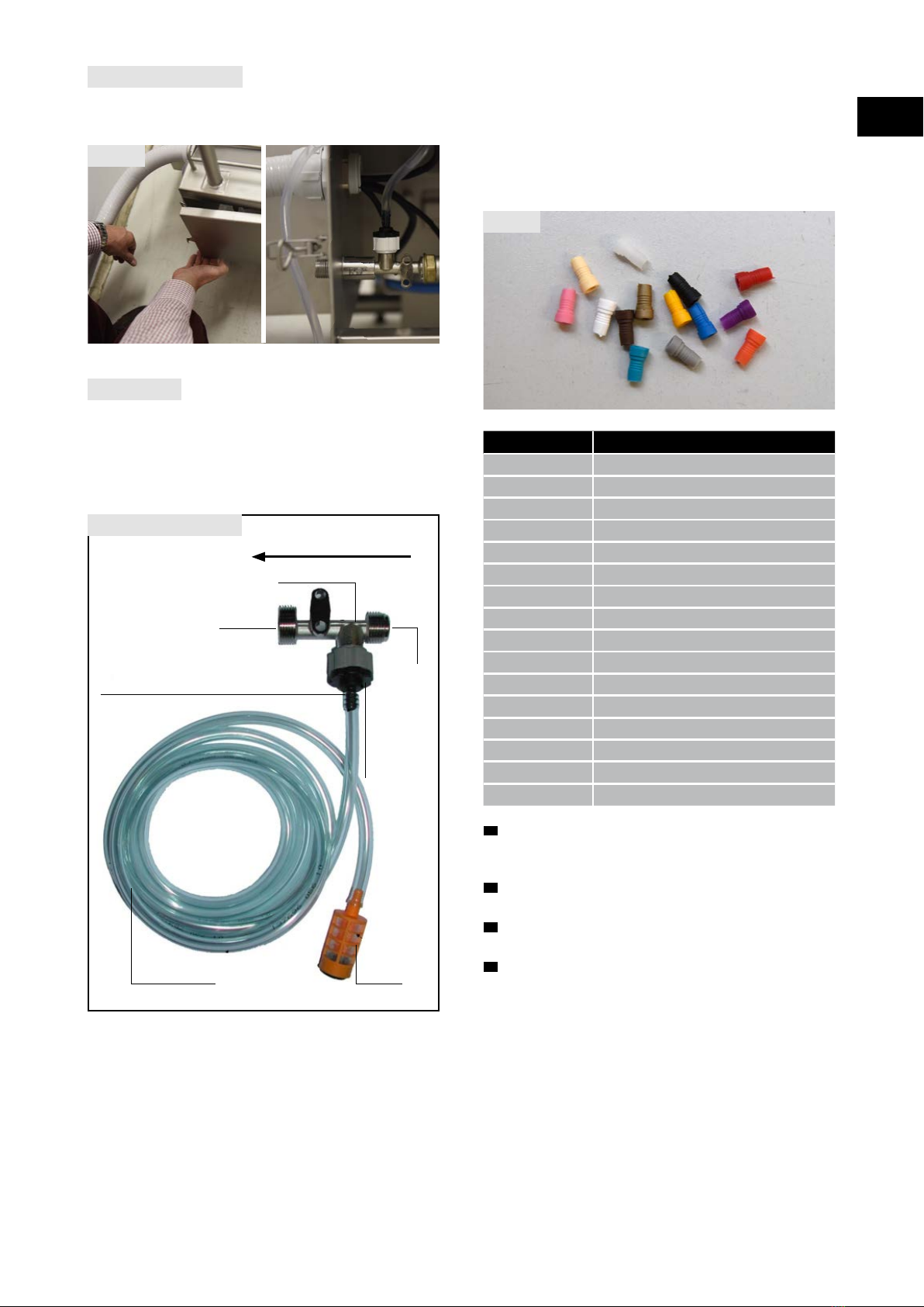
The dosage of detergent/disinfectant is done by nozzles in different
sizes – supplied with the machine (Fig. 18). To achieve the desired
concentration choose the corresponding nozzle (see below scheme).
The indications should be treated as guideline to nd the requested
concentration. Achieving optimal dosing results, tests should be
made.
The transparent nozzle is a stopper.
1. Have a look at the structure of dosing system – see section
"Service and maintenance" > Dosage > Structure of dosing
system.
2. Loose the transparent silicone hose by turning from the return
valve.
3. Plug the chosen nozzle with the narrow side on to the return
valve.
4. Plug transparent silicone hose on to the return valve.
Take care that the hose is wholly plugged and is not bended.
Dosing system
The dosing system prepares the mixture of water and detergent/
disinfectant in a certain proportion. This proportion will be deter-
mined by the installed nozzle.
To achieve optimal function use products having the same viscosity
than water. Don't use crystallised detergent/disinfectant.
Colour of nozzle
Admixture of detergent/disinfectant
without 22,00 %
grey 21,20 %
black 21,00 %
beige 17,00 %
red 12,20 %
white 9,00 %
blue 7,60 %
light brown 5,20 %
green 4,10 %
orange 3,10 %
dark brown 2,50 %
yellow 1,90 %
turquoise 1,10 %
purple 0,94 %
pink 0,35 %
transparent 0,00 % (used as stopper)
Fig. 18
Structure of dosing system
ow direction of water
G3/4”
connection
outlet
nozzle for dosage of detergent/disinfectant
chosen according following scheme
Transparent
silicone hose, 2 m Filter
G1/2”
connection
inlet
dosing system unit
Return valve
integrated
to the
dosing system
Fig. 17
EN
12
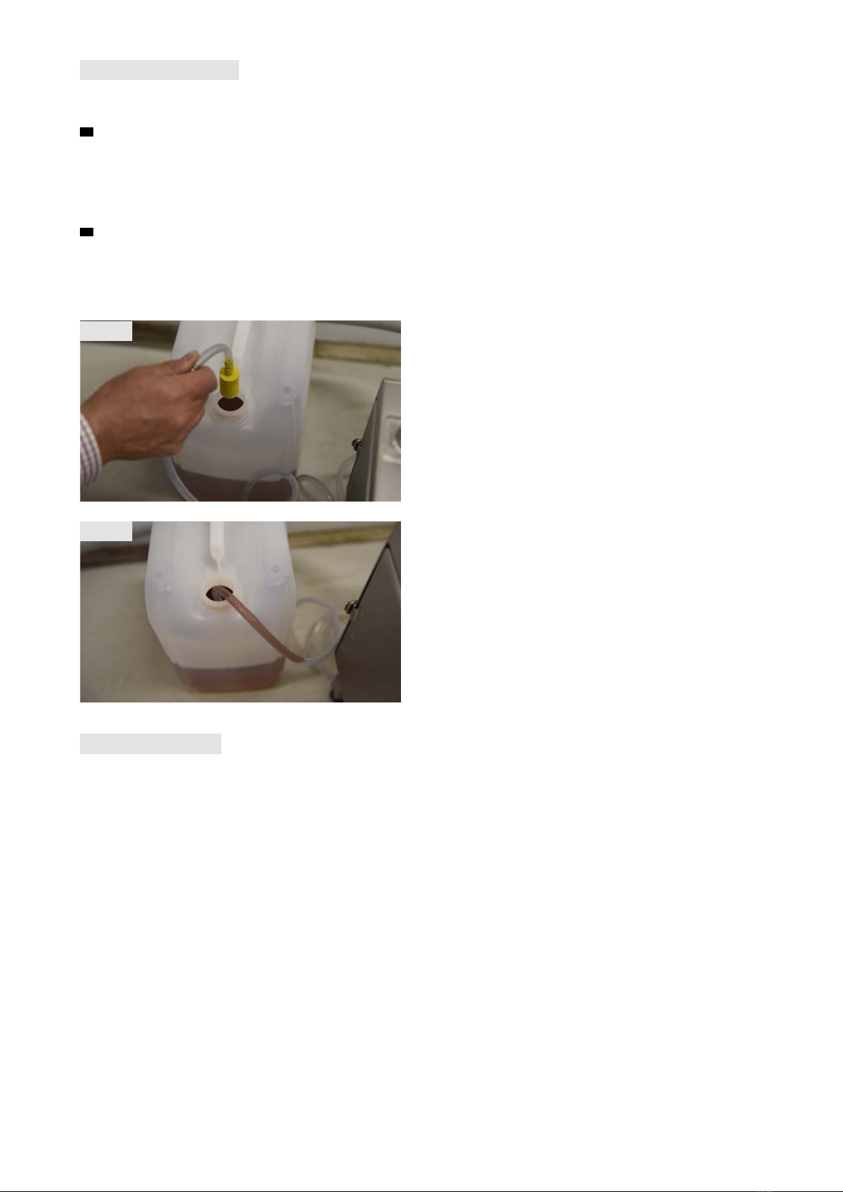
Dosing system – activation
Activation of detergent/disinfectant happens by water rinse of
the system
1. During initial operation put the lter device located at the
end of the transparent silicone hose into the detergent canister
(Fig. 19) – not belonging to the machine.
Detergent/disinfectant should not contain chlorine bleaching
ingredients because it could damage the surface, brushes and
other components.
2. Turn on the machine by pressing the push button until the dosing
medium has reached the level of the mixing tap (Fig. 20). To
achieve optimal function and mixture use products having the
same viscosity than water (water = viscosity of 1). Media having
higher viscosity (semiuid) could cause problems.
Dosing system – rinsing
We recommend to rinse the system for the detergent /disinfectant
regularly. However, basically when changing the detergent /disinfec-
tant canister or during maintenance work cleaning should be done.
Put the transparent silicone hose with lter device into a canister
with clear water and start the machine for 20-30 seconds.
Sediments and foreign objects could cause damage to the machine.
If the machine has not been used for a longer time we advise to
check that transparent silicone hose and lter device are free of
sediments. Just in case rinse the dosing system with clear water.
Fig. 19
Fig. 20

13
EN
Machine does not work
Canister is empty
Liquid is semiuid
No water ows after
starting the machine
Power supply interrupted or malfunction of components.
Contact qualied personnel
Take a full one
Try to absorb clear
water. If the machine
runs properly, dilute
the liquid before the
canister and/or take a
different nozzle
Is there a valve installed
before in machine?
Check that the valve is
not completely open
(*) Remove the trans-
parent silicone hose
from the return valve of
the dosing system. Put
your nger on the valve
to check if you feel a
suction effect
Yes - open this valve
No - the solenoid valve
does not open
To check it, close the
valve completely and
nd out if the liquid will
be absorbed
Suction effect visible
Suction effect not visible
Qualied personnel
should replace it
If the detergent is not
absorbed, turn to (*)
Ensure that the hose
or lter device is not
blocked by soilings
Ensure that the hose is
not damaged
Ensure that the nozzle is
not blocked
Remove the return valve. Check the 2 O-rings, the cone
and the spring (if necessary replace the dosing system
ap completely)
Clean thoroughly or re-
place the components.
Don't forget to install
the lter device on the
hose
If it is damaged replace
it. Don't forget to install
the lter device on the
hose
If the nozzle is blocked,
remove the blockage or
replace the nozzle
Trouble-shooting only by qualied personnel
Remove the nozzle and
clean it. Sediments could
block the system

14
Technical data:
Dimensions: 76 cm x 63,5 cm x 121,5 cm
(width x depth x height)
Weight: 50 kg
Connection load: 3-phase 400 V + grounding
Power: 0,18 kW
Protection category: IP55
Short term operation time (KB): 8 min
Noise emission: less than 80 dB(A)
Trouble-shooting only by qualied personnel
Machine operates without water
Water supply is closed or interrupted
Check water supply
Machine does not drain off waste water
Water outlet is blocked
Check water outlet - if necessary remove blockage
Motor stops or runs unproperly
Foreign objects inside
Unplug immediately the machine from power
supply. Search and remove foreign objects
(turn roller brush by hand)
Machine makes much noise during operation
Foreign objects inside
Unplug immediately the machine from power
supply. Search and remove foreign objects
(turn roller brush by hand)
or
Check correct installation of roller brush
15
EN
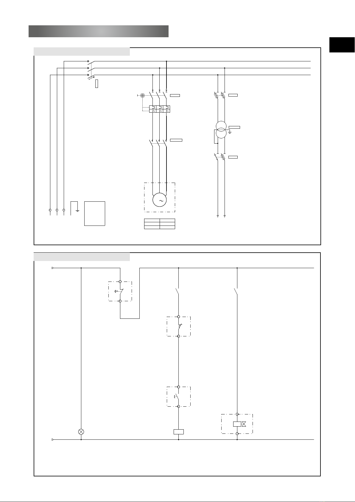
Wiring diagrams Neptun SC1
1 2 3 4 5 6 7 8 9 10 11 12 13 14 15 16 17 18 19 20
Motor for brush
Power connection
24V AC
push button
Motor
Power
Current rating
0.18KW
.....A
L3
1
L2
0
L3
119
7
L1
10
M
3
L1
-XP
L2
-XP
L3
-XP
-CF
NSYPLM3025
SCHNEIDER ELECTRIC
1
2
3
4
5
6
-IG
VCDN20
20A
-M1
U V W
1
2
3
4
5
6
-Q1
NO/03-9
- -
GV2ME04
8A
0,4-0,63A
-KM1
1
2
3
4
5
6
LC1K0610B7
03-9
0V AC
03-1
2gG
N 1
2
-F2
56015005
10x38
32A
P1 P2
S1 S2
-T1
ABL6TS04B
40VA
230+400V
24V
0.5aM
1
2
3
4
-F1
56010020
10x38
32A
24V AC
03-1
Wiring diagram I
Wiring diagram II
1 2 3 4 5 6 7 8 9 10 11 12 13 14 15 16 17 18 19 20
Control (brush)
Solenoid valve
(water supply)
345
2
7
1
7
6
8
0V AC
02-13
24V AC
02-13
X1
X2
-H1
24V
-XB
1
-XB
2
21
22
-AU
Emergency
push button
-Q1
13
14
02-8
A1
A2
-KM1
24V
j
j
j
a
02-81 2
02-83 4
02-85 6
03-1213 14
-XB
3
-XB
4
-FDC
1
2
Safety switch
(grid)
-XB
5
-XB
6
13
14
Push button
(brush)
-BP
24V
1
2
-EV
-XB
8
-XB
7
13
14
-KM1
03-9
Power control lamp

16
123456789 10 11 12 13 14 15 16 17 18 19 20
-XP
Conductor 4
L3
Conductor 3
02-2
IG:5 L2
Conductor 2
02-2
IG:3 L1
Conductor 1
02-1
IG:1
-ALIM
Power supply
Conguration clamping strip I
123456789 10 11 12 13 14 15 16 17 18 19 20
-XB
Conductor 3
3
3
3Conductor 1
03-9
FDC:1
4
545
4Conductor 2
03-9
Conductor 3
2
2
2Conductor 2
03-5
1
1
1Conductor 1
03-5
AU:21
6
6
6Conductor 2
03-9
KM1:A1
Conductor 3
8
8
8Conductor 2
03-12
EV:1
5
54
54 Conductor 1
03-9
BP:13
Conductor 3
7
7
7Conductor 1
03-12
-EV ARM
Solenoid valve (grid)
-BP ARM
Push button (brush)
-FDC ARM
Safety switch (grid)
-AU ARM
Emergency push button
Conguration clamping strip II
17
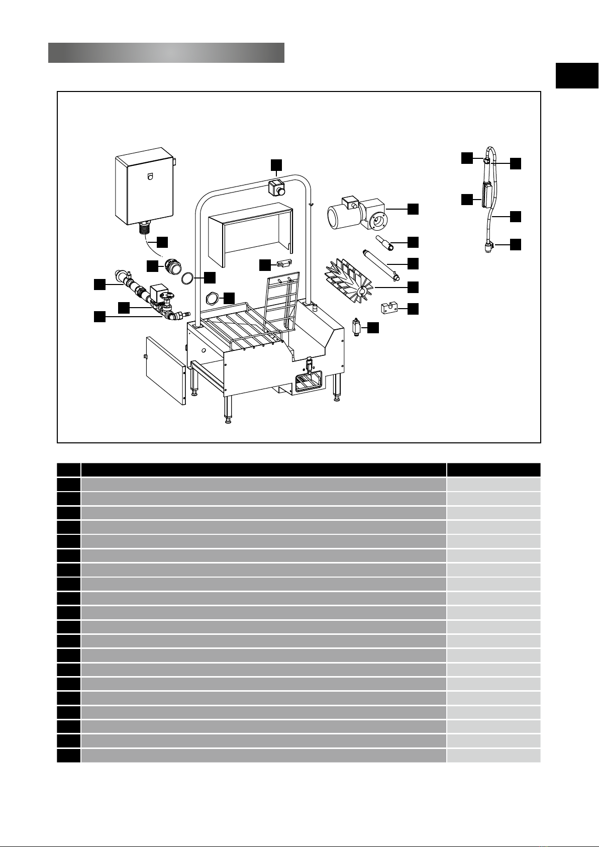
Part drawings Neptun SC1
11
7
2
3
119
6
10
12
13
14
9
8
4
5
16 17
15
18
Item Article Article No.
1 Coupling stainless steel + spring, 6 x 6 x 30 mm 06800101
2 Axle for brush, ø 150 x 330 mm, stainless steel 304 06800102
3 Brush blue, ø 150 mm, length 330 mm PBT 06800103
4 Stop Nylatron GSE 06800104
5 Position switch XCKP102 06800105
6 Gear motor MB2101 M50C LS63 p=0,18kW 06800106
7 Bearing Nylatron GSE 06800107
8 Nut Perfect CEPFV36 06800108
9 Gasket for connection piece PG36 06800109
10 Connection piece, grey, PG36 06800110
11 PVC hose GP, 40 x 46 - 2 lg = length 2 m 06800111
12 Dosing device chromed brass, ø 2,6 mm 06800112
13 Solenoid valve 24V-50Hz-NF-1/2", ø 11,5 mm 06800113
14 Valve to adjust water quantity, brass, 1/2" 06800114
15 Hand brush 06800115
16 Coupling for hand brush, stainless steel 304 06800116
17 Fixing piece for hand brush, stainless steel 304 06800117
18 Flexible PVC hose, length 1500 mm 06800118
19 Ball valve, stainless steel 1/2" 06800119
20 Push button 06800120
20
EN

Address: Weinsbergtalstraße 2-4 · 42657 Solingen · Germany
Postal address: P.O. Box 100507 · 42605 Solingen · Germany
Phone: +49(0)212-380 310 · Fax: +49(0)212-380 31-39
E-mail: info@heute-gmbh.de · Internet: www.heute-gmbh.de
EN
01-2016
This operating manual contains descriptions of our products, but it does not give any warranties for
specific properties or operational results. Authoritative is, unless otherwise specified, only the technical
base, at the time of delivery of the goods in combination with this manual, by Maschinenfabrik HEUTE
GmbH & Co. KG. The products and their design are subject to constant changes / improvements. We
reserve the right to apply technical changes, anytime.
This manual is protected by copyrights. All rights reserved. This manual shall not be copied, translated,
or otherwise modified, unless explicitly accepted, in writing, by the manufacturer (Maschinenfabrik
HEUTE GmbH & Co. KG).
Askims Skytteväg 4A · SE-436 51 Hovås · Sweden
Tel: +46(0)31 28 50 90 · Fax: +46(0)31 28 50 90
Table of contents
Other HEUTE Washer manuals


