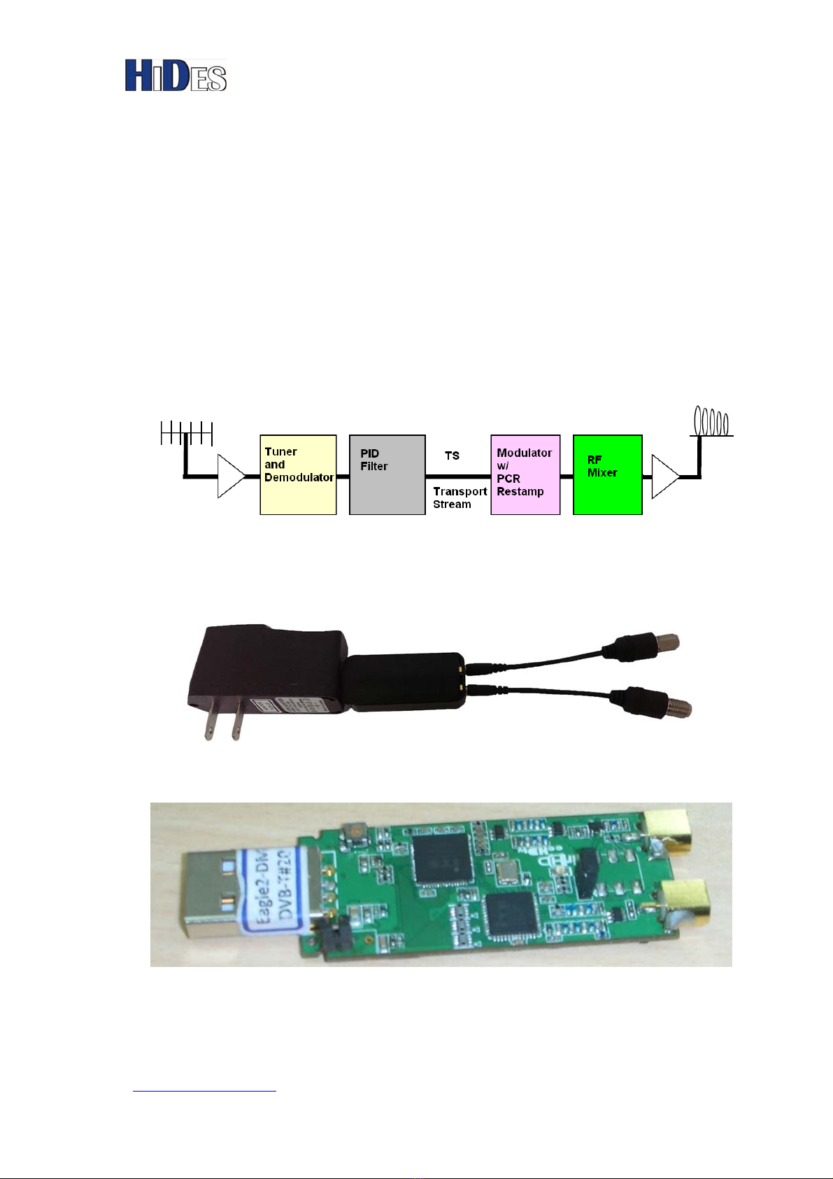
Easy HD Expressway! BR-101E QIG
WWW.HIDES.COM.TW 1
Table of Contents
1. Introduction..........................................................................................................2
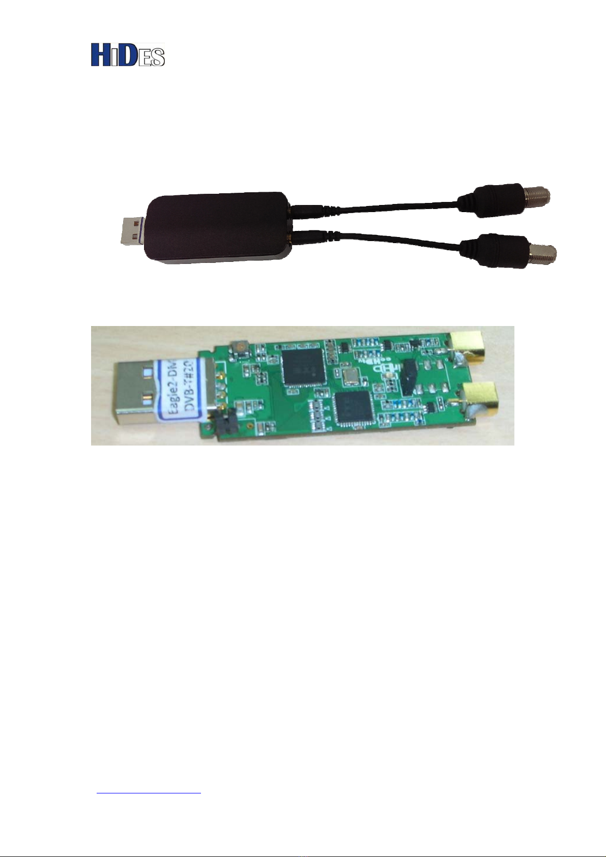
2. Board Descriptions...............................................................................................3
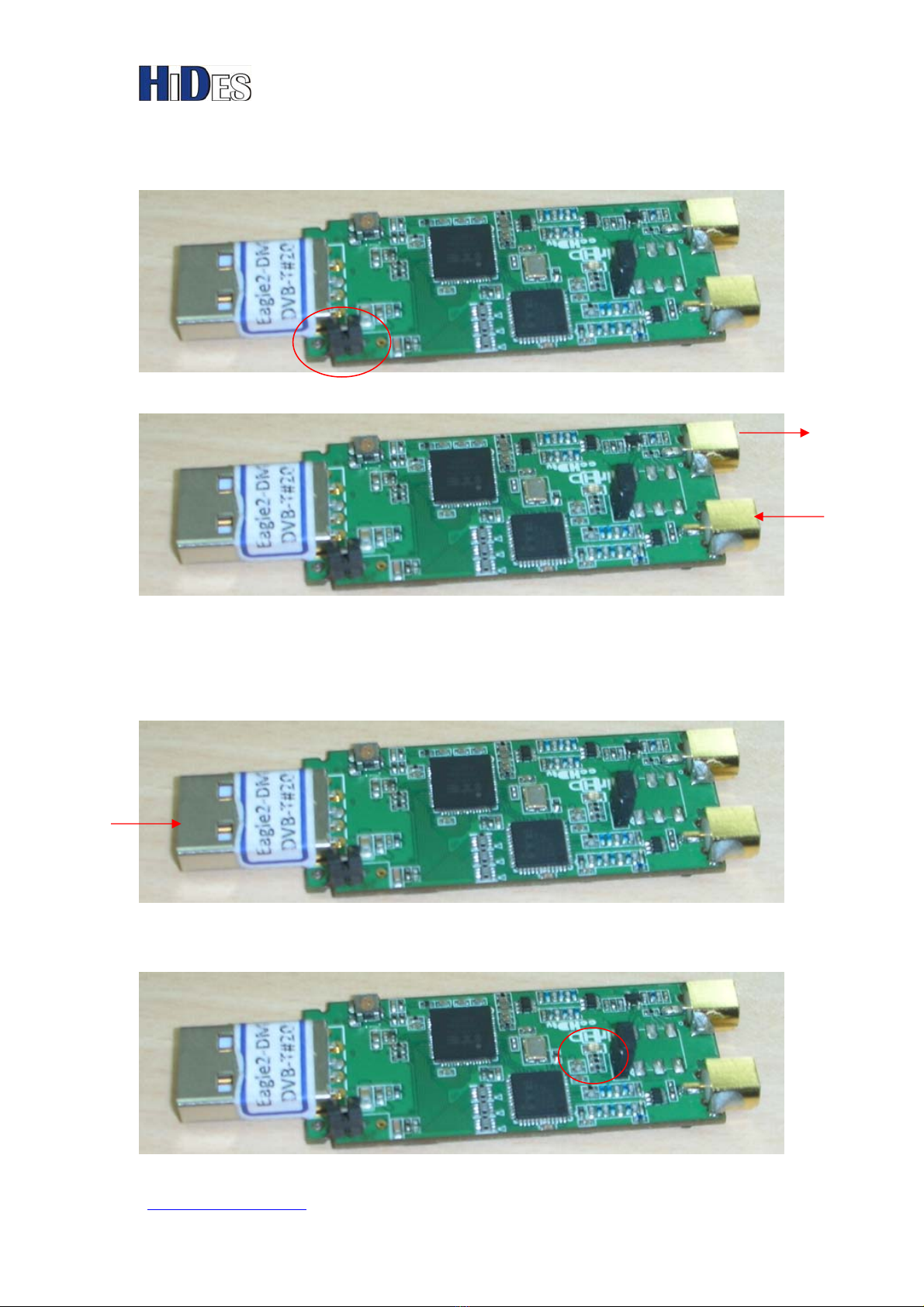
3. Easy Repeater Setup............................................................................................4
3.1. Short Jumper J1...........................................................................................4
3.2. Connect RF-in/out cable..............................................................................4
3.3. Apply 5V DC Power to the USB connector ...............................................4
3.4. Check LED State..........................................................................................4
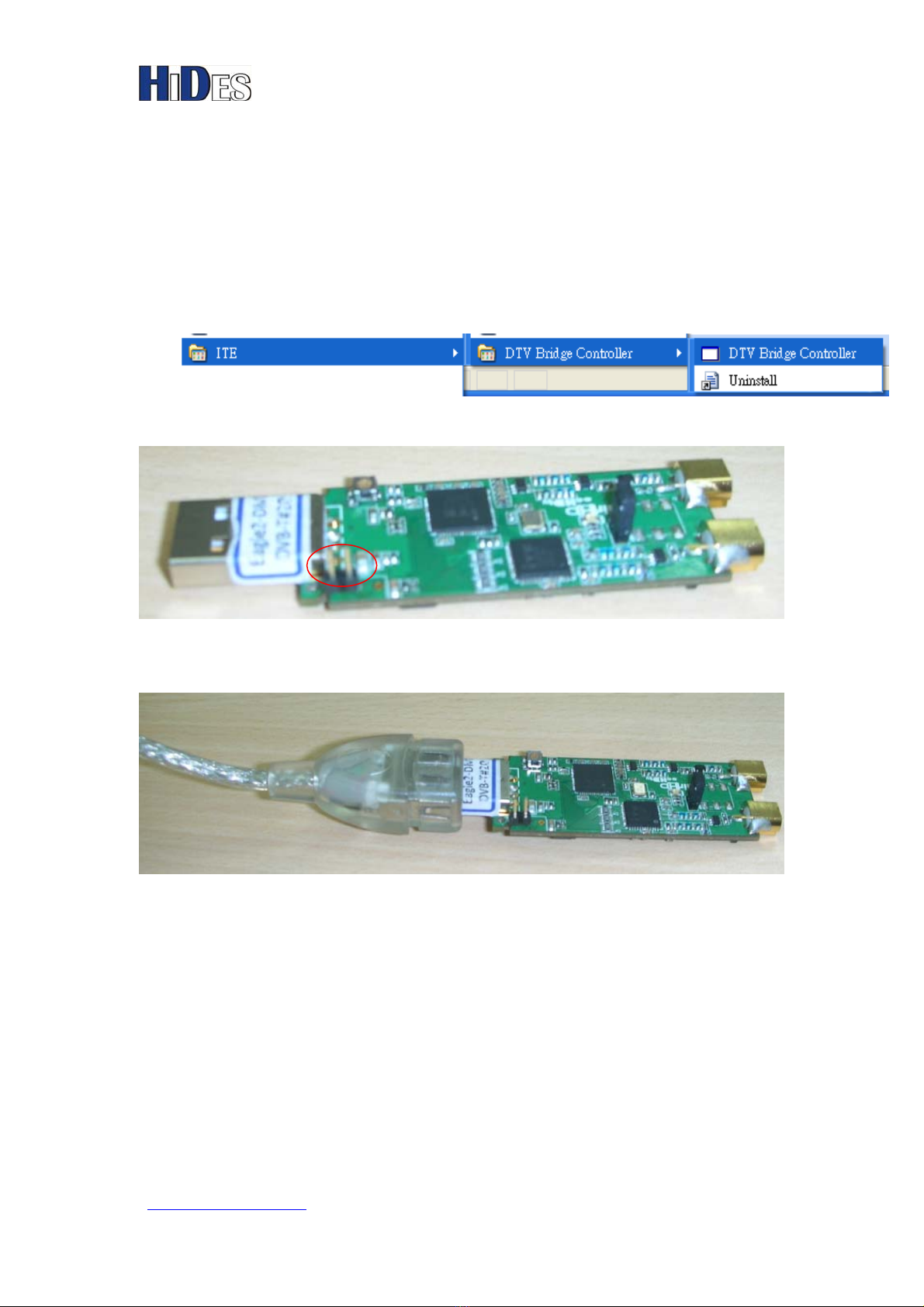
4. Setup PC/NB environment for configuration....................................................6
4.1. Run Setup.exe to install configuration software on your PC/NB............6
4.2. Remove Jumper J1 for USB configuration mode .....................................6
4.3. Connect USB port to your PC/NB..............................................................6
4.4. Driver install.................................................................................................6
5. Tool Usage-Configure ..........................................................................................8
6. Tool Usage- Firmware Update..........................................................................12
7. Tool Usage- Set Call Sign...................................................................................15
8. Tool Usage- Initialize EEPROM.......................................................................18
9. Filter Specifications............................................................................................21
9.1. BR-101E DTV Bridge Board U/V Filter Design.......................................21