HIDRIA R18R-080MPS-ET120B-01A01 Maintenance and service guide

INSTALLATION, MAINTENANCE AND USER'S GUIDE
FAN WITH ELECTRONICALLY COMMUTATED EXTERNAL-ROTOR MOTOR
Fan Code:
0318-4-1005
Fan type : R18R-080MPS-ET120B-01A01
&
Note :
Table of Contents :
01 SAFETY
02 TYPICAL FEATURES AND PROPER USE
03 OPERATING CONDITIONS
04 INSTALLATION AND CONNECTION
05 SPEED CONTROL
06 PUTTING INTO OPERATION
07 DIAGNOSTICS & TROUBLESHOOTING
08 PROTECTIVE FEATURES
09 MAINTENANCE, SERVICE AND CLEANING
10 TRANSPORT AND STORAGE
11 ErP, ROHS AND EMC DIRECTIVES
12 SERVICE ADDRESSES AND ADDITIONAL DATA
This document contains instructions and information for the operation, installation, connection, use and maintenance of
the product. Be sure to familiarize yourself with these instructions before working on this unit. Not paying attention to
these warnings and instructions may lead to malfunctions and failures or may seriously endanger human life. More
detailed information and instructions are available from the manufacturer on request.
Symbols :
WARNING - to indicate warning situation
WARNING - to indicate hot surfaces
DANGER due to electric shock
NOTE - indicate valuable information

USER'S GUIDE R18 AXIAL FAN , Iss: 6.05.2021
01
SAFETY
&
When unpacking the unit, grip the motor housing and lift it out very gently and carefully. Shocks
have to be avoided by all means! Wear safety shoes and cut-resistant gloves.
This appliance should only be installed or opened by qualified personnel.
This appliance can be used by children aged from 8 years and above and persons with reduced
physical, sensory or mental capabilities or lack of experience and knowledge if they have been
given supervision or instruction concerning use of the appliance in a safe way and understand
the hazards involved. Children shall not play with the appliance.
Cleaning and user maintenance shall not be made by children without supervision.
This appliance is solely intended as a built-in component and should not be operated otherwise.
Sufficient protection against accidental contact according to machinery directive 2006/42/CE has
to be safeguarded, especially for the rotating parts. Should there be a malfunction, it still has to
be safeguarded that the parts breaking off or flying away cannot cause serious damage or bodily
harm.
Do not operate this appliance in an explosive atmosphere!
Fan must be fixed to stationary housing with appropriate screws according to this guide.
This appliance is not intended to be built as a partition fan.
The electrical connection must correspond to this installation guide and enclosed connecting
diagram as desribed in chapter 4. INSTALLATION AND CONNECTION - page 6 of this
document.
Means for disconnection must be incorporated in the fixed wiring in accordance with the wiring
rules.
When connecting the unit to the power supply, dangerous voltages occur. Do not open the unit
within the first 5 minutes after disconnection from the power supply. Be sure that the unit is being
isolated.
Parallel operation of several units can cause dangerous charges of >50µC between AC line
terminals and PE after disconnection.
With control voltage fed, the motor will restart automatically after a power failure.
The risk of pulling into rotating part. Do not wear any loose clothing (e.g. tie) or jewellery.
Long hair must be protected with a cap. Risk of injury!
The electronics housing can get hot.
In case the external metal enclosure is accessible to user, maximum operating ambient
temperature is reduced to max.amb. 55°C.
© Copyright HIDRIA d.o.o., All rights reserved. Document is subject to change without prior notification.
2 / 10

USER'S GUIDE R18 AXIAL FAN , Iss: 6.05.2021
02 PROPER USE AND TYPICAL FEATURES
The fans are only intended for the transfer of air or air-like mixtures. They cannot be used in hazardous areas for the transfer of gas, mix vapours or
mixtures. Also cannot be used for transfer of solid components in transfer medium.
R14 axial fans with integrated external rotor ELECTRONICALLY COMMUTATED motor are not ready-to-use products, but designed as components for
air-conditioning, air supply and air extraction. The fans may only be operated when they are installed as intended & instructed, and when safety is
ensured by safety equipment according to EN 13857 or by other protection measures.
Axial fan is intended to be mounted on an air-conditioning, heat pump or evaporator heat exchanger housing with four screws so that the housing of application prevents
access to rotating parts from the rotor side and the protection grill prevents access to rotating parts from the front side. The heat exchanger's housing prevents also
access of water to axial fan from the rotor side.
This appliance is not intended to be built as a partition fan (mounting in outside windows or walls) unless it is built into an end-application which is
designed for that purpose.
The fan is intended to be permanently connected to fixed wiring.
The fan is intended to be connected to electrical power supply system with earthed neutral e.g. of type TN, TT.
The fans are only to be operated within the ranges specified on the motor name-plate.
Cycling operating mode: only with cycling via control signal (OFF=0V / ON=10V).
The manufacturer of the end application is responsible for keeping to the Electromagnetic compatibility (EMC) guideline 2014/30/EC.
The fan is designed for operating in 'pollution degree III' environment - applications acc. to EN 61800-5-1:2008.
Typical features
Variable Speed - setting via linear voltage input (0-10V) or PWM signal or other common ways.
High efficiency throughout the entire speed range.
Low-noise operation across the entire speed range.
Integrated EMC filter.
Sensor power supply 10VDC, max. 10mA.
Maintenance free ball-bearings and dynamically balanced rotating parts.
Control circuit is SELV isolated from main power supply (including an external power supply for sensors).
© Copyright HIDRIA d.o.o., All rights reserved. Document is subject to change without prior notification.
3 / 10

USER'S GUIDE R18 AXIAL FAN , Iss: 6.05.2021
03 OPERATING CONDITIONS
The fans are rated for S1 (IEC 60034-1) continuous operation.
Extreme ON-OFF switching operating must be avoided, because it has negative influence on life expectancy and power consumption.
Cycling operating mode should only with cycling ON/OFF via control signal (0/10V analog input or PWM input).
Do not cycling the power supply for cycling operating mode – use control signal! High 'In-rush current' can occur during cycling power supply!
Permissible ambient temperature is specified as indicated on the motor nameplate for actual fan and in chapter 03 OPERATING CONDITIONS in the
INSTALLATION, MAINTENANCE AND USER'S GUIDE.
If the end use requires compliance with the IEC/EN 60335 standards, due to the temperature limitation of the connecting cable, the temperature range
of the fan is limited to max. + 60 °C, even if the fan on the nameplate is specified for use up to a higher ambient temperature. If the fan is used at an
ambient temperature above 60 °C, always use temperature-resistant cables (PVC 105°C).
Figures on the motor name-plate refer to nominal values according to rule specified on the nameplate next to the written values. The rules (EN_60335,
'free air', 'max.load', 'max.eff.', cust. unit / cust. spec., UL, IEC 60034-1) are described in the example shown below.
Continuous sound pressure level may exceed 70dBA (depends of fan model).
Protection (motor & electronics): IP55 according to EN60529.
Power consumption in stand-by mode: les than 5W.
DIMENSIONS
Nominal diameter: 800 mm - see Appendix - technical drawing: VENTILATOR / R18R-080MPS-ET120B-01A01
Weight: 50 kg
NOMINAL DATA - defined according to ' MAX. LOAD '
Phase: 3~
Nominal Voltage: 400 V
Operating Voltage range: 380-480 V
Frequency: 50 Hz
Input power: 2900 W
Nominal current: 4,6 A
Rotational speed: 1140 RPM
Operating ambient temperature range: -25°C .. +65°C
Altitude: 2000 m
Insulation class: 155
Protection provided by PE: Class I
Overvoltage category (OVC): III
Operating humidity ambient: up to 95% (non condensing).
Max. pressure: 260 Pa
ErP DATA
Overall Efficiency, Effes: 47,8 %
Installation category: A
Efficiency category: static
Efficiency grade, N: 51,4
Variable speed drive: INTEGRATED
Power Input , Pelec: 2708,1 W
Airflow volume , qV: 18519 m³/h
Pressure Increase, ps: 250 Pa
Rotational Speed, n: 1146 RPM
Specific ratio: 1,002
Airflow volume max., qV: 27336 m³/h
Pressure Increase max., ps: 610 Pa
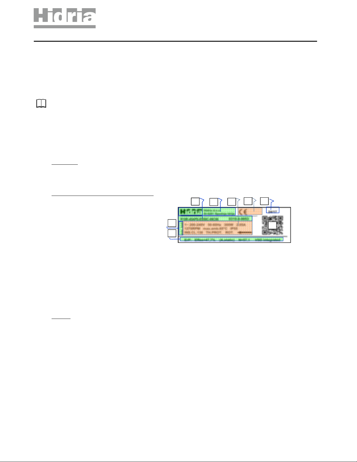
1. Fan type and code
2. Trade mark and manufacturer address
3. Nominal values (Voltage, frequency, lectric Power, Current...)
4. Certification marks
5. Date of production (week of the year/year)
6. QR code which includes code number, production date, serial number
and link to website.
7. Data acc. to U regulation 327/2011 ( rP)
8. NOT INDICAT TO WHICH STANDARD/RUL S COR SPOND DATA ON TH
NAM PLAT :
- N 60335-1 : Name-plate data are made according to standard EN
60335-1, Household and similar electrical appliances – Safet – Part 1,
Articles 10.1 and 10.2:
If an appliance is marked with rated power input, the power input at
normal operating temperature shall not deviate from the rated power
input b more than: + 20% if Pn<300W or +15% (or 60W whichever is
the greater) if Pn>300W.
If an appliance is marked with rated current, the current at normal
operating temperature shall not deviate from the rated current b more
than: +20% if In<1.5A or +15% (or 0,30A whichever is the greater) if
In>1.5A.
- FR AIR : Data on the nameplate established at a point 0Pa static
pressure at normal operating temperature.
- MAX LOAD : Data on the nameplate established at a point of maximal
static pressure regarding max. ambient temperature.
- MAX. FF. : Data on the nameplate established at a point of maximal
static efficienc at normal operating temperature.
- CUST. UNIT / CUST. SP C. : Data on the nameplate specified according
to customer specifications or at working point in customer's unit .
- UL - Data on the nameplate defined according to specifications in UL
standards.
- I C 60034-1 - Data on the nameplate established at a point of nominal
load according to standard for Rotational electrical machines.
An example of a label and explanation of the content:
1
2
5
6
7
8
3
4
© Copyright HIDRIA d.o.o., All rights reserved. Document is subject to change without prior notification.
4 / 10

USER'S GUIDE R18 AXIAL FAN , Iss: 6.05.2021
04 INSTALLATION AND CONNECTION
Mechanical installation:
This unit should only be installed by a qualified technician. Inspect the motor bearings for proper operation prior to installation.
Do not install the fan on an unstable surface. First install the device on the application, than connect the protective earth!
The method of fixing stated is not to depend on the use of adhesives since they are not considered to be a reliable fixing means.
The fan is primarily constructed for installation with rotor on bottom or with shaft in horizontal. For other possibilities please contact for manufacturer's
support.
Ensure that the air-gap between the fan impeller and the stationary housing is constant. Distortion due to an uneven surface of basis may lead to a fan
failure. Air-gap between blade and cone-inlet (housing) should be of min. 3 mm.
Fan must be fixed to stationary housing 8x M8 through 8 holes on diameter 816 mm of protection grid as indicated on enclosed technical drawing. Use
screws with property class of 8.8. Secure all threaded joints with e.g. Loctite or by using self-locking screws.
The system manufacturer or the machine builder is responsible that the inherent installation and security information are harmonized with the valid
standards and guidelines (ex. EN 13857). To prevent dangerous situation and possible injuries the height and the diameter of inlet cone must be
appropriate dimensions.
To lift the device with lifting devices, use the hangers provided for this purpose as shown on figure below. Always use suitable lifting equipment and
follow the instructions for safe work with lifting equipment. Failure to follow the instructions for safe work can lead to equipment damage or may
seriously endanger human life.
Electrical installation:
Main electrical installation must be protected against short circuit with e.g. circuit breaker: max.16A, 400Vac, Type B and installation must be
constructed properly according to valid national directives.
First install the device on the application, than connect the protective earth!
Means for disconnection must be incorporated in the fixed wiring in accordance with the wiring rules.
The fan is intended only to be connected to the fixed wiring or application’s circuit. An all-pole separating switch which must be incorporated to wiring
must disconnect also the fan.
This product can cause a d.c. current in the protective earthing conductor. Where a residual current-operated protective device (RCD) or monitoring
(RCM) device is used for protection in case of direct or indirect contact, only an RCD or RCM of Type B+ is allowed on the supply side of this product
and recommended sensitivity is 300mA with short time delayed intervention.
The electrical connection must correspond to the enclosed connection diagram.
© Copyright HIDRIA d.o.o., All rights reserved. Document is subject to change without prior notification.
5 / 10

USER'S GUIDE R18 AXIAL FAN , Iss: 6.05.2021
Recommended cable for power supply is a heat resistant PVC or other cable of appropriate quality (105°C) acc. to IEC 60227-5, e.g. H05V2V2-F, 4G
1.5 mm² (min.1.0 mm² - max. 2.5 mm² for stranded leads or max. 2.5mm² for solid conductors), outer diameter 6.0 - 11mm. Power supply cable could
include also additional leads for alarm circuit, e.g. H05V2V2-F, 6G 1 mm².
Recommended cable for alarm circuit is an ordinary PVC cable acc. to IEC 60227-5, e.g. H05V2V2-F, 2X 1 mm² (min.2X 0.50mm² - max. 2X 1.5mm²),
outer diameter 5.0 - 9.5mm.
Recommended cable for control circuit is an ordinary PVC cable, e.g. H05VV-F, 5X 0,5 mm² (min. 0,25 mm² - max. 0,75 mm² ) , no longer than 2m,
outer diameter 6.0 - 11mm and must be sufficient separated and isolated from the supply circuit and alarm circuit leads. No cable crossing inside the
connection box is allowed.
The connection cables must be prepared before opening the terminal cover. Only open the terminal cover in dry conditions and make sure that the
remains of conductors do not fall into the terminal compartment.
Follow the instructions for preparing the connecting cables as shown in the figure below. Cable sheath needs to stripped in the length of 50 - 60mm.
Ends of stranded wires needs to be provided with insulated ferrule (pin) length 8-10mm.
The fan is equipped with push-in spring terminals type PHOENIX SPTA or eqvivalent, that allow very easy connection.
A screwdriver of 0.6X3.5mm is necessary tool to remove conductor from the mains terminals and a screwdriver of 2.5x0.5mm is necessary tool to
remove conductor from the control circuit terminals.
Fan performed with terminal box is as supplied fitted with a sealing plug in the cable glands as a preventive against ingress of water or moisture inside
the terminal box. If the cable is not installed through the cable gland, sealing plug must remain in the gland! Connection box screws have to be
tightened with torque of 2,0Nm - 2,5Nm.
Secure connection cable to the fan guard grill or to the motor holder with cable fasteners so that the water flows away from the cable and cable gland.
Try to maintain as much distance between supply and control cable as possible (recommended distance > 5cm).
Cable-end of the fan must be connected in a dry environment to prevent that water penetrate through cable into motor housing.
Where the fan is installed in shaft-horizontal position, the cable exit on the motor must be in down position.
Before putting into operation, check the resistance of protective-earth circuit of the entire application. Cross-sectional area and material of PE conductor
may be the same as cross-sectional of phase conductor or see guide regarding PE conductor : standard EN 61800-5-1.
A second protective earthing conductor must be installed to ensure requirements of standard "EN 61800-5-1 , 4.3.5.5.2 Touch current in case of failure
of protective earthing conductor ". For that purpose an additional M4 of 12mm depth hole or additional PE terminal is provided on motor housing and
marked with PE symbol. More information about dimensions of second PE conductor please find in guidelines of mentioned EN or equivalent standard
(a cross-section of second Cu conductor should never be less than 2.5mm
2
).
CONNECTING DIAGRAM : See appended technical drawing - CONNECTING DIAGRAM 0302-0-0023
POWER SUPPLY : L1, L2, L3, PE
CONTROL CIRCUIT:
Control circuit is SELV isolated from main power supply (including an external power supply for sensors).
Enable: I01 - +10V
Modbus : RS A - RS B
0-10V analog input : 0..10V - COM
Sensor supply : +10V - COM
Slave control : OUT - GND
Alarm relay: COM - NC (SELV)
The device is compatible with Modbus protocol RTU. Please read additional instructions about Hidria EC Modbus parameters.
WARNING : Leakage current exceeds 3.5mA.
Short circuit rating: <10kA .
© Copyright HIDRIA d.o.o., All rights reserved. Document is subject to change without prior notification.
6 / 10

USER'S GUIDE R18 AXIAL FAN , Iss: 6.05.2021
05 SPEED CONTROL DIAGRAM
Rotation speed of a variable speed fan can be controlled by various signals:
- Linear voltage input (0-10V) or current input (4-20mA) or PWM input (PWM duty cycle 0-100%).
- MODBUS RTU protocol (Additional information are in documentation "Hidria EC Modbus parameters".
Linear voltage input is the most common and it is described below. The current input is also widely used, where long cables are necessary. PWM input
is used for electromagnetic noisy environments. PWM signal must be in square form with polarity the same as for linear voltage input (see connection
diagram). PWM duty cycle 0-100% correspond to 0-10V linear voltage input if the amplitude of the PWM voltage is Vp=10V. Amplitude of PWM signal
must not exceed 12Vp.
LINEAR VOLTAGE INPUT:
Linear input is factory adjusted to fit the customer’s sensor or other speed control reference. The input characteristic can be factory adjusted in terms of
increasing input sensitivity or attenuation.
For example: An air-cooled condenser is using a pressure sensor 0-20Bar => 0-10V, but the highest system pressure reached at maximum load is
16Bar => 8V. For optimal operation of the application the fan mounted on a condenser should run at max speed at 8V of input control voltage. In order
to achieve that, we need to adjust the input characteristic in a way the picture shows.
1.0V 1,2V Input voltage (0…10V)
Fan speed
HYSTERESIS
100%
1.2V 10V
Input voltage (0…10V)
Fan speed
CONTROL DIAGRAM
8V
adjusted
input curve
100%
1.2V 10V
Input voltage (0…10V)
Fan speed
INPUT CHARACTERISTIC ADJUSTMENT
0
200
400
600
800
1000
1200
Fan rotational speed (RPM)
Input Voltage (0...10 V)
SPEED CONTROL DIAGRAM
1.2 V 10 V
5 V
ON/OFF
HYSTERESIS
D=0.2V
In order to prevent cycling from standby to run mode or run to standby
mode a small hysteresis is implemented. The default value is
approximately 200mV.
Hysteresis can be factory-adjusted in order to achieve customer
requirements.
Linear voltage input (0-10V DC) can be used as 0 (4)-20mA current
input with an additional resistor of 500 Ohms between GND and 0-10V
connection.
Speed of a fan increases linearly with input voltage.
The fan operates in two different modes:
0-1.2 V…… Standby or stop mode
1.2-10 V….. Run mode
1.0-1.2V .....Hysteresis
© Copyright HIDRIA d.o.o., All rights reserved. Document is subject to change without prior notification.
7 / 10

USER'S GUIDE R18 AXIAL FAN , Iss: 6.05.2021
NFC / RFID WIRELESS COMMUNICATION
Fan has integrated NFC/RFID tag, based on ISO/IEC 15693, that can be used for advanced custom fan functionality configuration. NFC/RFID tag is
located as shown in the figure below. Before using NFC/RFID, the aluminium cover must be removed. Please see Hidria Fan App manual for more
information.
08 PROTECTIVE FEATURES
Short-circuit protection:
The motor and electronic controller are protected against short-circuit by built-in fuse.
Locked-rotor protection:
As soon the rotor is blocked, the motor is switched off electronically. After de-blocking, the motor will restart automatically.
Mains under voltage:
If mains voltage falls below the nominal value the motor will keep running with degraded performance. Below 320V, the motor will be switched off
electronically in stand-by mode. When mains voltage returns to correct value, the motor will restart automatically.
In the specific case, the undervoltage protection may switch off the fan to stand-by mode, for example, fan running or testing at high pressure drop and
low voltage.
Over temperature protection:
Internally connected thermal protector to protect electronic and motor against over temperature.
06 PUTTING INTO OPERATION
Before first start you should check:
a. Appropriate installation and electrical connection, especially resistance of the protective-earth (PE) circuit (max. 100mΩ).
b. If safety equipment is in place and motor protection device is in function.
c. If the impeller can rotate freely once the unit is mounted and the right direction of rotation is assured.
Only if all dangerous situations are excluded, the fan may be put into operation!
Switch ON the power supply.
Switch ON the device via the control signal and apply the speed setting voltage/signal and check the direction of the rotation and the smoothness of
running.
© Copyright HIDRIA d.o.o., All rights reserved. Document is subject to change without prior notification.
8 / 10

USER'S GUIDE R18 AXIAL FAN , Iss: 6.05.2021
07 DIAGNOSTICS & TROUBLESHOOTING
Fan does not start or run - alarm rele status OPEN or FLASHES:
Possible causes: missing power (no line voltage), low voltage (under 185V), extremely thermally or mechanically overloaded or fan failure (short circuit
of electronic or windings).
Check line voltage, check value and polarity of control signal, check that rotor is free to rotate.
Fan does not start or run - alarm rele status CLOSE:
Possible causes: missing or inadequate control signal.
Check value and polarity of control signal.
Fan runs with half of desired speed - alarm rele status CLOSE:
Possible causes: Low supply voltage, inadequate control signal or fan overheating.
Check line voltage, check control signal, check temperature and sufficient airflow of cooling air or loss of motor cooling.
Attention !
In the event of fan failure is detected (short/open in circuit of electronics/windings), never try to repair the fan, but replace it with new one or/and return
defected fan to the manufacturer for repair or replacement.
ALARM RELAY DIAGNOSTICS
Alarm relay contact OPEN on ERROR. Alarm relay contacts capability: max. 2A-250VAC cos fi0.6, max. 3A-30VDC.
Errors on which alarm relay OPEN:
- Rotor locked in duration exceeding 10s.
- Motor winding overheating.
- Power module overheating.
- DC link undervoltage.
- Internal communication error.
The alarm relay needs approximately 3-4 seconds after switching on the line voltage to become operable - change contacts to status CLOSE if no
malfunction is detected.
MULTI COLOUR LED DIAGNOSTICS
GREEN STATUS:
- NO malfunction is detected.
ORANGE STATUS:
- Missing controll signal (if function 'Emergency operation' is active).
- Electronics / Motor / Power module high temperature.
- Break active.
RED STATUS:
- Rotor locked.
- Motor overheating.
- Power module overheating.
- DC link undervoltage error.
- Internal communication error.
© Copyright HIDRIA d.o.o., All rights reserved. Document is subject to change without prior notification.
9 / 10

USER'S GUIDE R18 AXIAL FAN , Iss: 6.05.2021
09 MAINTENANCE, SERVICE AND CLEANING
Before any maintaining or repairing operation is carried out, the unit must be securely disconnected from any power supply source!
This unit should only be opened or maintained or repaired by a manufacturer or by a manufacturer-qualified and authorised personnel.
Ensure that the fan is switched off from the supply mains before removing the guard.
Fan has integrated NFC/RFID tag, based on ISO/IEC 15693, that can be used for fan functionality configuration. Please see Hidria Fan App manual for
more information.
If an already installed fan is switched OFF for a long period in a humid atmosphere, it should be switched ON for minimum of two hours every month to
remove any moisture that may have condensed inside the motor.
0
Cleaning
Regular inspection, if required, and cleaning when necessary to prevent imbalance due to the build-up of dirt. Clean the fan`s flow area.
Blades must be cleaned carefully to avoid damage to them.
Never use a high-pressure cleaner or water spray for cleaning.
Wet cleaning under voltage may lead to an electric shock.
Do not use any aggressive paint solvent cleaning agents.
For cleaning, use just a moist cloth. You can clean the entire fan with a moist cloth.
If water penetrates into the motor, the motor windings must dry before restarting.
Cleaning and user maintenance shall not be made by children without supervision.
10 TRANSPORT AND STORAGE
Unit must be transported only in its original package.
When the fan's transported with wood spacer on pallet, take care with the cables (in the situation that fan has connection cables). When unpacking fans,
transported in such a way, grip the fan to protection grill. Do not apply any force for the cable(s).
When transporting fans mounted on final units (apparatus), take care that they are properly secured and don`t touch other devices which are
transported near or on to.
Store the fans in the original packaging in a dry area protected from the weather. Do not store fans in extreme heat and cold.
We recommend a maximum of one year of storage. After a long period of storage we recommend that you inspect the bearings for proper operation
before installation.
Permissible transport / storage temperature range: -40°C .. +80°C.
Permissible transport / storage humidity : 5 - 95%.
11 ErP, ROHS AND EMC DIRECTIVES
Fan must be mounted in appropriate way to achieve optimal efficiency and life expectancy. We suggest assembling fan in long inlet cone, with fan blade
trailing edge aligned with outlet edge of inlet cone.
Only environment friendly, recyclable materials according to RoHS2 (2011/65/EU) and REACH (EC1907/2006) directive are used in the product.
Disposal must be carried out professionally and environmentally friendly in compliance with regulations applicable in your country.
Design of the product enables simple decomposition of all components. Main components are appropriate marked for easy further handling at product
end-of-life.
Complying with the EMC standards has to be established on the final appliance, as different mounting situations can result in changed EMC properties.
12 SERVICE ADDRESSES AND ADDITIONAL DATA
Please refer to the homepage at www.hidria.com for a list of our subsidiaries worldwide.
Hidria reserves the right to change any specifications or data without notice.
The manufacturer will not accept liability for any resulting damages caused by the non-observance of this manual or any unauthorized modification to
the system.
0
© Copyright HIDRIA d.o.o., All rights reserved. Document is subject to change without prior notification.
10 / 10
This manual suits for next models
1
Table of contents
Other HIDRIA Fan manuals

HIDRIA
HIDRIA R18R-091MPS-ET120B-01A02 User manual

HIDRIA
HIDRIA R10R-50APS-ES50B-09C17 User manual

HIDRIA
HIDRIA R10R-63LPS-ES50B-03C11 User manual

HIDRIA
HIDRIA 0310-4-0071 User manual

HIDRIA
HIDRIA R10R-40APB-ES50B-02C01 User manual

HIDRIA
HIDRIA 0314-4-0166 User manual

HIDRIA
HIDRIA R10G-2810KR-ES50B-13C2 User manual

HIDRIA
HIDRIA 0314-4-0089 User manual

HIDRIA
HIDRIA 0310-4-0127 User manual

HIDRIA
HIDRIA R10R-56LPS-ES50B-04C10 User manual