High-End Technology Super Sniper 90 User manual

Page 1/34
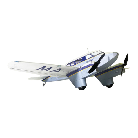
Super Sniper 90
High Performance EDF Jet for 90mm EDF units
Thank you and congratulations on your decision of buying one of our
EDF Jet Kits.
Before you start building the Sniper 90, please go through the
instructions on the following pages and study the pictures and
building guidelines carefully.
Due to the high speed that this jet is capable of, extra care needs to
be taken during the building process to ensure that the model can
perform flawlessly when in the air later.
You will find that this model is quick and easy to assemble.

Page 2/34
Super Sniper 90 Technical Data
Wingspan: 1120 mm (44’’)
Length: 1200 mm (47.2’’)
Weight: 2400 ~ 2800 grams depending on power setup
Fan Size: Single 90mm Electric Ducted Fan Unit
RC Equipment needed to complete the model:
•3-5 channel Computer Radio with 3-6 Servos
o3x HS-82MG for Aileron & Elevator
o1x HS-81MG for Rudder (optional)
o1x HS-81MG for Nose Gear Steering (optional)
o1x HET-9gram for Retract Valve (optional)
•90mm Fan unit (e.g. HET-RC 9305)
•600 Brushless Motor (e.g. HET-RC Typhoon 600-42)
•Brushless Speed Controller (e.g. HET 90A ESC)
•LiPo Battery to match Motor and ESC (e.g. 3700mAh 7S 30C)
Building equipment required:
•30 min epoxy
•5 min epoxy
•Milled fiberglass
•Micro Balloons
•Drill (e.g. Dremel tool) with 1, 1.5 and 2mm drill
•X-acto Knife
•CA Glue with accelerator
•Sandpaper (220-180)
A rotary tool, such as a Dremel, will greatly help in the building process.
A drum sander and cutting disk is highly recommended to cut the necessary
retract openings into the fiberglass fuselage.

Page 3/34
Kit Contents:
The Sniper 90 kit includes the following items:
1x Sniper 90 Fiberglass Fuselage
2x Sniper 90 Wing panels
1x Sniper 90 Elevator
1x Sniper 90 Fiberglass Rudder
1x Clear Canopy with Plywood canopy frame
1x Nose Gear Retract Mount
3x Wheels
1x Nose wheel strut
2x Main wheel strut
1x Bungee Hook
Various Push Rods
Mounting screws
Clevises
Control Horns

Page 4/34
Step 1: The Wing
Prepare the 2 wing panels and main spars.
The main spar consists out of 2 parts which
need to be sandwiched together with 30min
epoxy.
Carefully remove the covering around the
edge of the wing root to enlarge the glue
surface. Ensure that you do not cut into the
wood as this might weaken the root rib.
Next dry fit the main spar and slot the wing
halves together. Ensure that both halves
align fully at the wing root without a gap. If
required, sand the wing root to achieve the
desired fit.
In order to strengthen the glue joint, we
recommend that you roughen the wing root
surface. A needle can be used to create
numerous small pin holes in the wood.

Page 5/34
Use 30 minute Epoxy to glue the wing together (you can add a bit of milled fiberglass to
add strength). All steps below are executed while the epoxy is still wet.
First, glue the 2 spar halves together with 30 min epoxy. Next push some epoxy into the
spar slot of the left wing. Push the spar into the left wing slot (ensure the spar is inserted
the correct way around).
Push some epoxy into the spar slot of the right wing. Apply some epoxy to the wing spar
and to the wing root on both sides.
Push the wing together. Clean off the excess epoxy with cleaning alcohol.
Align both wing halves at the wing root. Use masking tape to press both wings panels
together and to secure the alignment until the epoxy has fully cured.
Let the epoxy cure fully before moving the wing.
Turn the wing around and locate the servo
cut-outs. When choosing your servo,
measure both servo and servo cut-out depth
to ensure that the servo is flush with the
wing surface once installed. Place your
servo on top of the cut-out as shown and
trace its outline. Cut along the trace to
enlarge the servo hatch for your servo type.
Turn the wing around and open the servo
wire channel in the top surface. You can
either cut them with a sharp knife or use an
old wire/needle, heated over a flame to cut
away the covering. Do the same with the
wing mount screw holes at the trailing
edge.

Page 6/34
Back to the servo installation.
Center the servo with your radio and install
a straight servo arm.
Use sandpaper to clean the inside of the
servo cutout. Place the servo in the cut-out
and check the servo arm clearance above
the wing surface. Ensure that the arm is
long enough to allow a pushrod to be
connected and to move freely.
Push the servo wire through the servo
channel (ensure the cable is long enough).
Next, glue the servo in place with 5 minute
epoxy. You can either glue on the servo
directly with its casing or wrap the servo in
tape or shrink tube before gluing it.
Roughen the servo surface with sandpaper
before applying glue.
Tape the servo cable ends to the top surface of the wing to avoid them from falling back
into the servo wire channel.

Page 7/34
Next the aileron can be installed. Locate
the CA hinge slots for each aileron. Trial fit
the aileron. If necessary, carefully lengthen
the slots to reach a perfect fit between
aileron and wing. Remove the aileron and
glue the CA hinges into the wing with thin
CA Glue. Once cured slot in the aileron
and apply thin CA to glue it in place.
Attach the supplied clevis (or use your
own) to the push rod. Use some masking
tape to stick the pushrod to the wing. The
pushrod should run parallel to the servo
centerline and touch the servo horn as
shown. A Z-Bend will later be used to
secure the rod to the servo. Move the
rudder horn so that it lines up with the
clevis. The holes in the rudder horn should
be directly above the pivot line between
aileron and wing.
Mark the rudder horn position and drill the
holes for the mounting screws. Fix the horn
in place. Enlarge the hole of the servo arm
with a suitable drill to the size of the
pushrod.
Center the servo again with your radio and
measure the length between horn and servo
in neutral position. Make a z-bend and
install the pushrod. Cover the servo and
cutout with a piece of the supplied iron on
film.

Page 8/34
Step 2: Main retract Installation
Skip to step 3 if you wish to bungee launch the plane
Locate the retract mounts under the
covering. Trace the outline. Cut away the
covering with a sharp knife or heated metal
rod as shown in the previous step.
The retract mount and wheel well is fully
prepared for you. Unless you would like to
enlarge the wheel well skip the next step to
the right.
Note: Due to the slim profile of the wing
the retract mount is installed directly
behind the main spar. If there is a need to
enlarge the wheel well you can only do so
in the direction of the trailing edge.
Enlarging the wheel well (2’’ wheel cutout
shown above).
Mark the new wheel well size (only enlarge
towards the trailing edged) and cut out the
well with a sharp knife. Ensure that you do
not damage the top skin of the wing.
The foam core can be cut with a knife or
similar to the foil cutting described earlier
with the help of a heated metal rod.
Once all foam has been removed, clean the
excess glue from the top sheeting with
sandpaper to get a smooth surface.

Page 9/34
Trial fit the retract unit and mark its
position.
Drill the mounting holes.
Drill a small channel through the foam
from the retract air hose position to the
servo cannel. Route the airline though the
channel out of the wing. If you have
enlarged your wheel well simply cut a
groove into the foam wall of the gear well.
This step only needs to be performed if the
wheel well was enlarged in the previous
step.
Place a carton or fiberglass sheet into the
wheel well as shown. The carton sheet will
later form the wall of the wheel well to
protect the foam from damage. Trace the
outline long the wing skin.
This step only needs to be performed if the wheel well was enlarged in the previous step.
Remove the carton/fiberglass sheet and cut along the line drawn in the previous step. Test
fit the carton lining again and if required adjust where necessary. Install the retract unit
and route the airline through the channel created in the previous step. Use 5 min epoxy to
glue the carton sheet in place. Ensure that the airline is tucked behind the wall.

Page 10/34
Install the retract unit and trial fit the strut
and wheel. Bend the wire strut as shown by
around 15-20° to get slightly trailing retract
struts.
Align the wheels to run straight and mark
the position of the grub screw. File a flat
spot at the grub screw position. Repeat the
same with the wheel collar to securely fix
the wheel to the wire strut.
The following steps should only be performed
if necessary. Some builders might find a small
gap between wing and fuselage, which can
easily be closed to enhance the planes looks.
Tape the servo wires securely to the wing and
cover the top surface with glad wrap plastic
foil. This will create a non stick surface for the
filler.
Use tape inside the fuselage to create a
boundary line as shown. This will
prevent the filler from running inside
the fuselage.
Mix 30 minute Epoxy with Micro
Balloons until the epoxy forms a thick
paste with similar consistency as
Toothpaste. Apply a thick rope to area
marked gray in the above picture. Stay
clear of the mounting holes.

Page 11/34
Apply some oil to the mounting screw and blind nut thread and mount the wing in place.
The oil will prevent the screw from getting locked in case a little bit of epoxy will come
to close. Turn the plane around.
Epoxy/Micro Balloon paste should have been pushed out between the wing and the
fuselage. Use a cloth and lots of cleaning alcohol to clear all excess epoxy before it cures.
Make sure you get a smooth transition between fuselage and wing.
In case you still have a gap or cleaned away to much epoxy push some of the paste into
the gap (with a scrap piece of balsa or a medical syringe).
Once cured remove the wing. The wing should now sit perfectly on the fuselage.

Page 12/34
Step 3: Fan Setup & Elevator installation
The above picture shows the HET 9305
Fan and Typhoon 600-42 Motor used for
our Sniper. Do not yet install the motor in
the fan unit. The installation of the fan will
be easier if the motor is installed at a later
time (we made life complicated for this
manual and installed the motor first !).
Insert the Fan into the fuselage and
carefully slide it into the intake duct.
Rotate the fan so that the 2 mounting lugs
are horizontal. Once in place use making
tape to secure it in place.
View the plane from the rear and shift the
fan until you have a straight thrust line.
Tape the fan in place so that it can’t move.
The kit includes 2 fan mounting brackets
which should be used to secure the fan in
place. Locate the 6 plywood pieces and
assemble them as shown in the drawing
above.

Page 13/34
With the fan still in place, carefully slide
the 2 mounting brackets under each of the
fans mounts. Due to production differences
the intake duct might be slightly off center.
Hence it can happen that the brackets are
slightly too broad. Carefully trim them to
shape until you get a close but not tight fit
between fuselage and fan. Slightly sand the
fuselage at the places where the mounts
will be glued later.
Next, tack the bracket in place with a drop
of CA glue. Once both brackets are
secured, remove the fan unit.
Permanently glue the mounts in place with
30 minute epoxy and milled fiberglass.
Once cured, install the fan and mark the
screw location on the brackets. Drill the
holes and secure the fan in place.
The exhaust duct is fabricated out of the
supplied clear PVC sheet. Place the sheet
on the template and trace the outline. Mark
the last line of the template on the PVC
sheet. This will be the glue line for later.
Cut the sheet and roll it together.
Depending on the fan you choose for your
Sniper adjust the exhaust nozzle diameter.
HET 9305 Fans should use an exhaust
diameter of 78mm. Midi Fan nozzles
should be smaller at 75mm. Glue the sheet
together with CA. Use your fan housing as
a guide on the intake side.
Once the duct is finished check the outlet
diameter of the fuselage. The slim end (75-
78mm diameter) of the duct should fit
inside the fuselage without folding. In case
the exhaust diameter of the fuselage is too
small, slightly enlarge it by cutting a few
mm off the end of the fuselage with a
cutting disk. Always only mark and cut a
few mm. Check and trim again if
necessary.

Page 14/34
Mark the position of the fan mounting
latches on the large end of the PVC duct
and cut them out (~2cm deep). Install the
fan in the fuselage. Slide the duct from the
rear into the fuselage. Fold it as shown to
fit the large end in.
Once inside, slide the intake end over the
fan unit. Mark the excess ducting sticking
out of the rear. Remove the duct and trim
the end to shape.
Prepare the elevator. Locate the CA hinge
slots in the elevator fin. Trial fit the
elevator rudder. If necessary, carefully
lengthen the slots to reach a perfect fit
between fin and rudder. Remove the rudder
and glue the CA hinges into the fin with
thin CA Glue.
Once cured, slot in the elevator rudder and
apply thin CA to glue it in place

Page 15/34
Fix the elevator to the fuselage with the
screws provided. Do not glue it on yet.
There are multiple options to install the
elevator linkage. The rudder horn can
either be installed beside the exhaust duct
as shown above or installed below the
exhaust duct so that it is hidden inside the
fuselage. In the case of an installation
beside the fuselage, a slot needs to be cut
into the fuselage to allow either the
pushrod or the servo horn to exit.
In the next steps, we will describe the
installation of the hidden linkage.
For the hidden installation of the elevator
linkage a cutout needs to be made in the
fuselage to allow the rudder horn to go
inside. Remove the elevator, mark a 2cm
slot as shown above and cut it out.
Please note: the slot should be made as
close as possible to side wall of the
fuselage to allow the rudder horn to clear
the exhaust duct.
Attach the elevator again and check the
rudder horn clearance. Enlarge the slot if
required until the elevator can move freely.
Check the clearance of the rudder horn
with the exhaust duct and shorten the
rudder horn if required.
Mark the horn position, drill the mounting
holes and secure it in place.

Page 16/34
Prepare the elevator servo. The servo will be glued to the bottom of the fuselage directly
behind the elevator recess. Wrap the servo in heat shrink tube. Roughen the surface.
Center the servo with your radio and install the servo arm as shown.
The Servo will be installed in the fuselage as shown above. Before it can be glued,
roughen the bottom surface of the fuselage with sandpaper.
Assemble the elevator linkage from the supplied threaded rod with one clevis at each end.
Trial fit the pushrod and servo in the fuselage. Adjust the length of the pushrod as
required. Use masking tape to secure the elevator in neutral position.
Once everything is adjusted glue the servo into the fuselage with 5min epoxy mixed with
a bit of milled fiberglass.

Page 17/34
Step 4: Working Rudder (optional)
Skip to step 5 if you do not wish to install a working rudder
The Super Sniper 90 can be equipped with
a working rudder. Installation of the rudder
will ease cross wind take off and landing.
The rudder is cut out of the supplied
fiberglass fin.
Mark a straight line along the molded line
in the rudder (highlighted in black in the
picture above). Also mark the bottom of
the rudder 10mm parallel to the base of the
fin.
Cut the rudder out. Use a small saw or
cutting disk. Wear a face mask when
cutting the polyester.
Prepare two 6x6x160 mm and two
6x3x50mm balsa spruces to close the
rudder and create a surface for the hinges.
Taper the spruce at one end to allow it to
fully slide in the fin and rudder. Trial fit the
spruce.
Glue the 4 parts into the fin and rudder
with 30min epoxy. The balsa blocks should
form a flush end with both the fin and the
rudder edges.
Remove excess epoxy with a cloth and
cleaning alcohol.
Once the glue is dried, you should have a
sturdy fin and rudder which perfectly
match each other.
Use sandpaper to smoothen the
balsa/fiberglass edge on the fin.

Page 18/34
Next you need to sand off a few mm on
one side of the rudder. This will create an
angle to allow the rudder to move later.
Hold the rudder to the fin to check the
max deflection and sand until the desired
angle is reached.
Sand of 1mm of balsa and fiberglass from
the bottom end of the rudder to allow it to
move freely when it is installed.
Cut slots for the CA hinges into the rudder.
Ensure the slots are in the correct edge.
The slots should be cut directly between the
balsa piece and the fiberglass skin.
Glue the hinges with thin CA.
Once the glue has cured, hold the rudder
against the fin and mark the hinge position.
Cut the slots and glue the rudder in place
with thin CA. Check the movement.
The rudder pushrod position will heavily
depend on the later servo position. As the
clearance between duct and fuselage top
is not very big we have decided to install
the servo further forward in the fuselage.
If you are using a very slim servo which
can fit under the fin inside the fuselage,
without blocking the exhaust duct you can
choose a more direct linkage for your
Sniper.
The picture above shows the
recommended routing of the pushrod
inside the fuselage.
As the pushrod will be routed inside the
fuselage, mark a 20mm long exit slot for the
pushrod on the fin (use the picture above as
reference). Cut the slot out.

Page 19/34
Roughen the pushrod sleeve with sand
paper and insert it into the slot. The sleeve
should be routed through the fin and exit
it at the bottom of the leading edge. This
will create a gentle angle and avoid
binding of the pushrod inside the sleeve
later. If required, drill a hole though the
spruce inside the fin to allow the sleeve to
pass through. Glue the sleeve to the inside
of fin with 5 min epoxy.
Step 5: Installing the Rudder
Before the fin can be glued in, place a slot
needs to be cut into the fuselage to allow the
pushrod sleeve to pass through. The rough
position of the slot is shown above. Trial fit
the rudder to ensure that the slot is long
enough.
Trial fit the rudder. If required, sand the
bottom edge of the rudder until it fits.
Roughen the inside of the rudder fin with
sandpaper. Lightly sand the glue area on
the fuselage. Apply 30min epoxy mixed
with milled fiberglass to the inside of the
fin and press it in place. Use masking tape
to position the fin at a 90° angle to the
elevator fin. Remove excess epoxy with
cleaning alcohol.
Use 2 ply wood spars as shown in the
previous picture to create a wise. The spars
will press the sides of the fin against the
fuselage until the epoxy has cured.
Check again that the fin is straight (at a 90°
angle to the elevator fin and wings).

Page 20/34
Step 6: Rudder Servo installation (optional)
Skip to step7 if you do not wish to install a working rudder
After the epoxy has cured, turn the model
around. The pushrod sleeve should now
protrude into the fuselage similar to the
picture above. It will point towards the left
or right fuselage wall.
The wall it is closest to, will be the rudder
servo installation wall. Due to the tight fit
between fuselage and duct, the servo needs
to be shifted slightly forward of the fan
unit.
If it is not done yet, roughen the sleeve
with sandpaper. Next glue it in place along
the fuselage side. Use 5min Epoxy. (Also
look at the next picture to see how the end
of the sleeve is positioned against the fan
mount). Use balsa scraps on both sides of
the sleeve to improve the bond. You can
use scrap wood dowels to push the sleeve
against the fuselage wall as shown. Once
the epoxy has cured these braces are
removed.
The end of the sleeve will be glued against
the bottom of the fan mount. Again use a
piece of balsa scrap to wedge it in place.
Once the glue is dried, shorten the sleeve
inside the fuselage, directly behind its glue
spot on the fan mount. Insert the pushrod in
the sleeve. Leave 30mm space between the
threaded end and the end of the sleeve in
the fuselage. Cut the pushrod at the end of
the rudder.
Mark the rudder horn position (the line of
holes in the horn should line up with the
pivot point of the rudder) and drill the
holes. Secure the pushrod to the rudder
horn with a z-bend. Insert the z-bend before
you fix the horn in place.
Use masking tape to fix the rudder in
neutral position.
Other High-End Technology Toy manuals
