HIMA HIMax X-DO 12 01 User manual
d
X-DO 12 01
HIMax®
Relay Output Module
Manual

HI 801 023 E Rev. 5.00 (1244)
All HIMA products mentioned in this manual are protected by the HIMA trade-mark. Unless noted otherwise,
this also applies to other manufacturers and their respective products referred to herein.
All of the instructions and technical specifications in this manual have been written with great care and
effective quality assurance measures have been implemented to ensure their validity. For questions, please
contact HIMA directly. HIMA appreciates any suggestion on which information should be included in the
manual.
Equipment subject to change without notice. HIMA also reserves the right to modify the written material
without prior notice.
For further information, refer to the HIMA DVD and our website at http://www.hima.de and
http://www.hima.com.
© Copyright 2012, HIMA Paul Hildebrandt GmbH + Co KG
All rights reserved
Contact
HIMA Address
HIMA Paul Hildebrandt GmbH + Co KG
P.O. Box 1261
68777 Brühl, Germany
Phone: +49 6202 709-0
Fax: +49 6202 709-107
E-mail: info@hima.com
Revision
index Revisions
Type of Change
technical
editorial
4.00 New edition for SILworX V.4 X X
5.00 Updated edition for SILworX V.5 X

X-DO 12 01 Table of Contents
HI 801 023 E Rev. 5.00 Page 3 of 52
Table of Contents
1Introduction 5
1.1 Structure and Use of the Manual 5
1.2 Target Audience 5
1.3 Formatting Conventions 6
1.3.1 Safety Notes 6
1.3.2 Operating Tips 7
2Safety 8
2.1 Intended Use 8
2.1.1Environmental Requirements 8
2.1.2 ESD Protective Measures 8
2.2 Residual Risk 9
2.3 Safety Precautions 9
2.4 Emergency Information 9
3Product Description 10
3.1 Safety Function 10
3.1.1 Reaction in the Event of a Fault 10
3.2 Scope of Delivery 10
3.3 Type Label 11
3.4 Structure 12
3.4.1 Block Diagram 13
3.4.2 Indicators 14
3.4.3 Module Status Indicators 15
3.4.4 System Bus Indicators 16
3.4.5 I/O Indicators 16
3.5 Product Data 17
3.5.1 Current Measurement 19
3.6 Connector Boards 20
3.6.1 Connector Boards with Screw Terminals 21
3.6.2 Terminal Assignment for Connector Boards with Screw Terminals 22
3.6.3 Connector Boards with Cable Plug 23
3.6.4 Pin Assignment for Connector Boards with Cable Plug 24
3.7 System Cable X-CA 012 25
3.7.1 Cable Plug Coding 26

Table of Contents X-DO 12 01
Page 4 of 52 HI 801 023 E Rev. 5.00
4Start-up 27
4.1 Mounting 27
4.1.1 Wiring Outputs not in Use 27
4.2 Mounting and Removing the Module 28
4.2.1 Mounting a Connector Board 28
4.2.2 Mounting and Removing the Module 30
4.3 Configuring the Module in SILworX 32
4.3.1 Tab: Module 33
4.3.2 Tab: I/O Submodule DO12_01 34
4.3.3 Tab: I/O Submodule DO12_01: Channels 35
4.3.4 Submodule State [DWORD] 35
4.3.5 Diagnostic Status [DWORD] 36
4.4 Connection Variants 37
4.4.1 Wiring Actuators with Ohmic Load 37
4.4.2 Wiring Actuators with Inductive Load 38
4.4.3 Wiring one Actuator to Redundant Modules 39
4.4.4 Wiring Actuators via Field Termination Assembly 40
5Operation 41
5.1 Handling 41
5.2 Diagnosis 41
6Maintenance 42
6.1 Maintenance Measures 42
6.1.1 Loading the Operating System 42
6.1.2 Proof Test 42
7Decommissioning 43
8Transport 44
9Disposal 45
Appendix 47
Glossary 47
Index of Figures 48
Index of Tables 49
Index 50
X-DO 12 01 1 Introduction
HI 801 023 E Rev. 5.00 Page 5 of 52
1 Introduction
The present manual describes the technical characteristics of the module and its use. It
provides information on how to install, start up and configure the module in SILworX.
1.1 Structure and Use of the Manual
The content of this manual is part of the hardware description of the HIMax programmable
electronic system.
This manual is organized in the following main chapters:
Introduction
Safety
Product Description
Start-up
Operation
Maintenance
Decommissioning
Transport
Disposal
Additionally, the following documents must be taken into account:
Name
Content
Document no.
HIMax
System Manual
Hardware description of the
HIMax system
HI 801 001 E
HIMax
Safety Manual
Safety functions of the HIMax
systems HI 801 003 E
HIMax
Communication Manual
Description of communication
and protocols
HI 801 101 E
SILworX Online Help (OLH) Instructions on how to use
SILworX
-
First Steps
Introduction to SILworX
HI 801 103 E
Table 1: Additional Valid Manuals
The latest manuals can be downloaded from the HIMA website at www.hima.com. The revision
index on the footer can be used to compare the current version of existing manuals with the
Internet edition.
1.2 Target Audience
This document addresses system planners, configuration engineers, programmers of
automation devices and personnel authorized to implement, operate and maintain the devices
and systems. Specialized knowledge of safety-related automation systems is required.
1 Introduction X-DO 12 01
Page 6 of 52 HI 801 023 E Rev. 5.00
1.3 Formatting Conventions
To ensure improved readability and comprehensibility, the following fonts are used in this
document:
Bold:
To highlight important parts
Names of buttons, menu functions and tabs that can be clicked and used
in SILworX.
Italics:
System parameter and variables
Courier
Literal user inputs
RUN
Operating state are designated by capitals
Chapter 1.2.3 Cross references are hyperlinks even though they are not particularly
marked. When the cursor hovers over a hyperlink, it changes its shape.
Click the hyperlink to jump to the corresponding position.
Safety notes and operating tips are particularly marked.
1.3.1 Safety Notes
The safety notes are represented as described below.
These notes must absolutely be observed to reduce the risk to a minimum. The content is
structured as follows:
Signal word: danger, warning, caution, notice
Type and source of danger
Consequences arising from the danger
Danger prevention
The signal words have the following meanings:
Danger indicates hazardous situation which, if not avoided, will result in death or serious
injury.
Warning indicates hazardous situation which, if not avoided, could result in death or serious
injury.
Warning indicates hazardous situation which, if not avoided, could result in minor or modest
injury.
Notice indicates a hazardous situation which, if not avoided, could result in property damage.
NOTICE
Type
and source of damage!
Damage prevention
SIGNAL WORD
Type and source of danger!
Consequen
ces arising from the danger
Danger prevention

X-DO 12 01 1 Introduction
HI 801 023 E Rev. 5.00 Page 7 of 52
1.3.2 Operating Tips
Additional information is structured as presented in the following example:
i
The text corresponding to the additional information is located here.
Useful tips and tricks appear as follows:
TIP
The tip text is located here.
2 Safety X-DO 12 01
Page 8 of 52 HI 801 023 E Rev. 5.00
2 Safety
The following safety information, notes and instructions must be strictly observed. The product
may only be used if all guidelines and safety instructions are adhered to.
The use in Ex-Zone is permitted if additional measures are taken.
2.1 Intended Use
HIMax components are designed for assembling safety-related controller systems.
When using the components in the HIMax system, comply with the following general
requirements
2.1.1 Environmental Requirements
Requirement type
Range of Values
Protection class
Protection class II in accordance with IEC/EN 61131-2
Ambient temperature
0...+60 °C
Storage temperature
-40...+85 °C
Pollution
Pollution degree II in accordance with IEC/EN 61131-2
Altitude
< 2000 m
Housing
Standard: IP20
Supply voltage
24 VDC
Table 2: Environmental Requirements
Exposing the HIMax system to environmental conditions other than those specified in this
manual can cause the HIMax system to malfunction.
2.1.2 ESD Protective Measures
Only personnel with knowledge of ESD protective measures may modify or extend the system
or replace modules.
NOTICE
Device damage due to electrostatic discharge!
When performing the work, make sure that the workspace is free of static and wear
an ESD wrist strap.
If not used, ensure that the device is protected from electrostatic discharge, e.g., by
storing it in its packaging.

X-DO 12 01 2 Safety
HI 801 023 E Rev. 5.00 Page 9 of 52
2.2 Residual Risk
No imminent danger results from a HIMax module itself.
Residual risk may result from:
Faults in the engineering
Faults in the user program
Faults in the wiring
2.3 Safety Precautions
Observe all local safety requirements and use the protective equipment required on site.
2.4 Emergency Information
A HIMax controller is a part of the safety equipment of a system. If the controller fails, the
system adopts the safe state.
In case of emergency, no action that may prevent the HIMax systems from operating safely is
permitted.

3 Product Description X-DO 12 01
Page 10 of 52 HI 801 023 E Rev. 5.00
3 Product Description
The X-DO 12 01 relay module is intended for use in the programmable electronic system (PES)
HIMax.
The module can be inserted into any of the base plate slots with the exception of the slots
reserved for system bus modules. For more information, see System Manual (HI 801 001 E).
The module is equipped with 12 potential-free relay outputs with forcibly guided contacts. The
relay outputs are suitable for connecting ohmic and inductive loads.
The module has been certified by the TÜV for safety-related applications up to SIL 3
(IEC 61508, IEC 61511 and IEC 62061) as well as Cat. 4 and PL e (EN ISO 13849-1).
Refer to the HIMax Safety Manual (HI 801 003 E) for more information on the standards used to
test and certify the module and the HIMax system.
3.1 Safety Function
The module performs its safety function using two safety relays that are connected in series and
continuously monitored by the safety-related processor submodule.
The safety function is performed in accordance with SIL 3.
3.1.1 Reaction in the Event of a Fault
If the safety-related processor system of the module detects a module fault during operation, the
module adopts the safe state and all the outputs are de-energized in accordance with the 'de-
energize to trip principle'. If a channel fault occurs, only the affected channel is switched off.
The module activates the Error LED on the front plate.
3.2 Scope of Delivery
The module must be installed on a suitable connector board to be able to operate. If a Field
Termination Assembly (FTA) is used, a system cable is required to connect the connector board
to the FTA. Connector boards, system cables and FTAs are not included within the scope of
delivery.
The connector boards are described in Chapter 3.6, the system cables are described in
Chapter 3.7. The FTAs are described in own manuals.
X-DO 12 01 3 Product Description
HI 801 023 E Rev. 5.00 Page 11 of 52
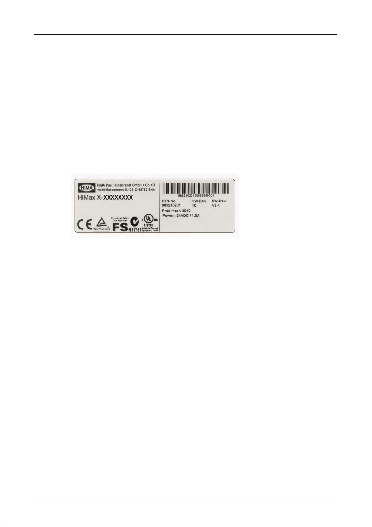
3.3 Type Label
The type label specifies the following important details:
Product name
Mark of conformity
Bar code (2D or 1D code)
Part number (Part-No.)
Hardware revision index (HW Rev.)
Software revision index (SW Rev.)
Operating voltage (Power)
Ex specifications (if applicable)
Production year (Prod-Year:)
Figure 1: Sample Type Label

3 Product Description X-DO 12 01
Page 12 of 52 HI 801 023 E Rev. 5.00
3.4 Structure
The module is equipped with 12 relay outputs. Each relay output is switched by two contacts in
series. After every cycle, the module reads the status of the forcibly guided contacts and
compares it status with the output variables.
The relays in use have forcibly guided contacts (EN 50205) and can be used for safety
shutdowns. Forcibly guided contacts are connected with one another mechanically such that the
normally open and the normally closed contacts cannot be closed simultaneously.
All 12 relay outputs are electrically safely isolated from one another. Each relay output is safely
isolated from the voltage supply of the module by its own contact circuit. For safe insulation, the
air and creeping distances are designed in accordance with IEC 61131-2 for overvoltage class II
up to 300 V.
For burner management systems, the switching current must be limited to 60 % of the maximum
allowed value using an external fuse in accordance with EN 298 and EN 50256 (VDE 0116).
At least two monitored relays must be used to shut down the entire fuel supply safely. HIMA
recommends performing the wiring such as specified in Chapter 4.4.3.
WARNING
Electric shock, damage to module!
The module is not designed for connecting three
-phase current!
Only one phase can be connected to the X
-DO 12 01 module. Connecting three-phase
current is not permitted!
The safety-related 1oo2 processor system for the I/O module controls and monitors the I/O
level. The data and states of the I/O module are made available to the processor modules via
the redundant system bus. The system bus has a redundant structure for reasons of availability.
Redundancy is only ensured if both system bus modules are inserted in the base plates and
configured in SILworX.
The module is equipped with LEDs to indicate the status of the relay outputs, see Chapter 3.4.2.
The module measures current on each channel (see Chapter 3.5.1) and issues a warning if the
number of switching operations per channel exceeds 250 000.
X-DO 12 01 3 Product Description
HI 801 023 E Rev. 5.00 Page 13 of 52
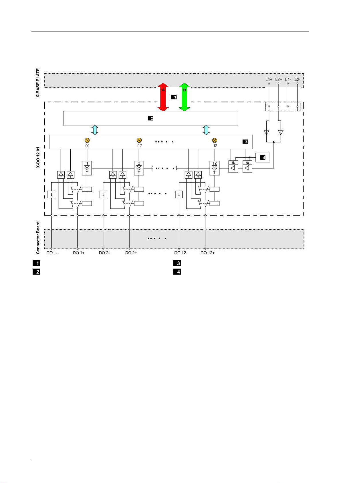
3.4.1 Block Diagram
The following block diagram illustrates the structure of the module.
System Busses
Safety-Related Processor System Interface
Watchdog
Figure 2: Block Diagram
3 Product Description X-DO 12 01
Page 14 of 52 HI 801 023 E Rev. 5.00
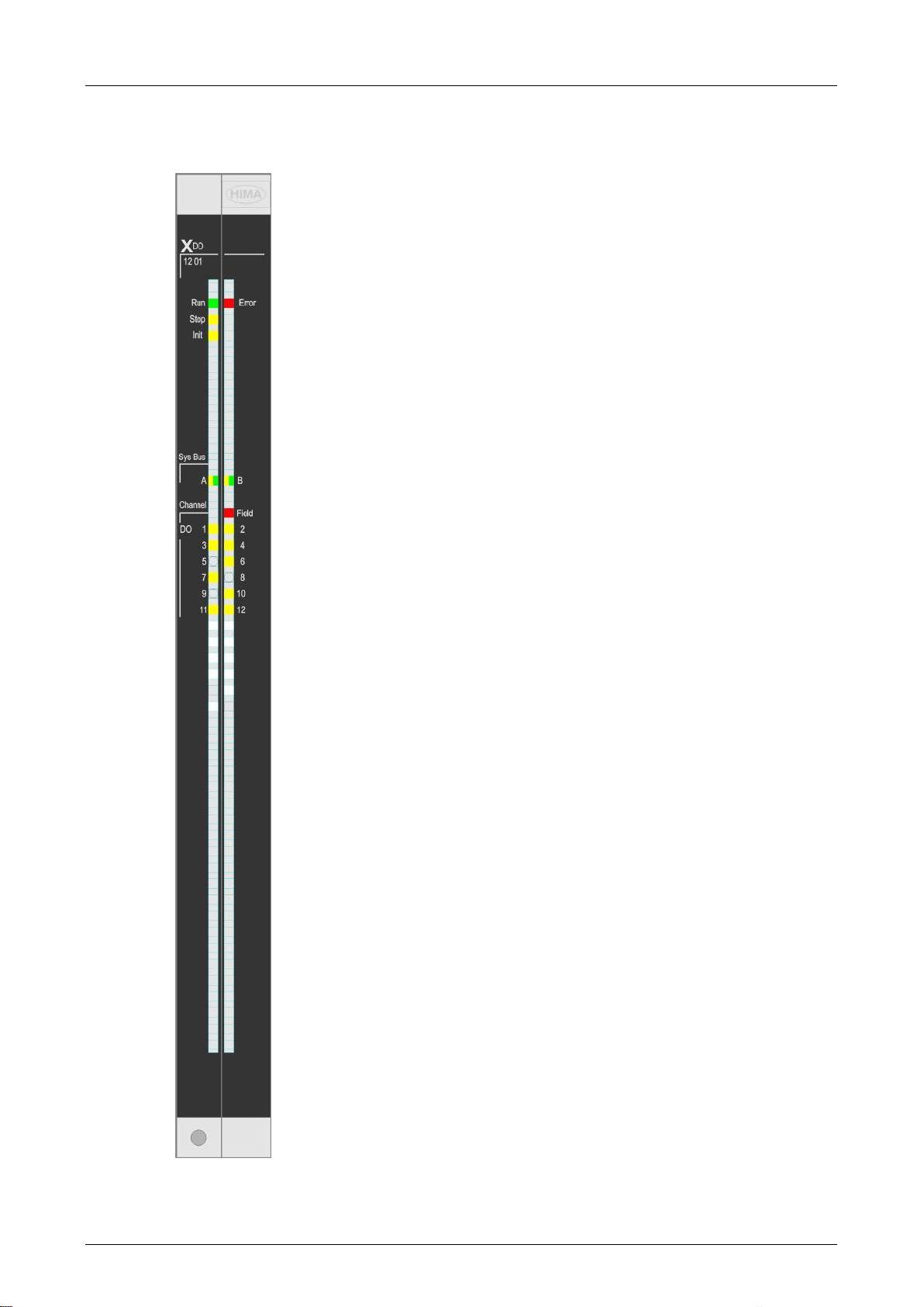
3.4.2 Indicators
The following figure shows the LED indicators for the module.
Figure 3: Indicators
X-DO 12 01 3 Product Description
HI 801 023 E Rev. 5.00 Page 15 of 52
The LEDs indicate the operating state of the relay module.
The LEDs on the module are divided into three groups:
Module status indicators (Run, Error, Stop, Init)
System bus indicators (A, B)
I/O indicators (DO 1...12, Field)
When the supply voltage is switched on, a LED test is performed and all LEDs briefly flash
simultaneously.
Definition of Blinking Frequencies
The following table defines the blinking frequencies of the LEDs:
Name
Blinking Frequencies
Blinking1
Long (approx. 600 ms) on, long (approx. 600 ms) off
Blinking2
Short (approx. 200 ms) on, short (approx. 200 ms) off, short (approx. 200 ms)
on, long (approx. 600 ms) off
Blinking-x
Ethernet communication: Flashing in sync with data transfer
Table 3: Blinking Frequencies of LEDs
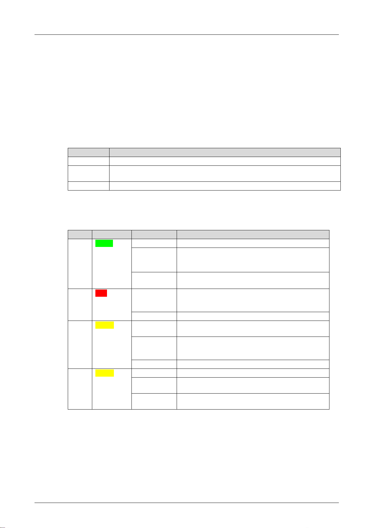
3.4.3 Module Status Indicators
These LEDs are located on the front plate, on the upper part of the module.
LED
Color
Status
Description
Run
Green
On
Module in RUN, normal operation
Blinking1
Module state:
STOP/OS_DOWNLOAD or
OPERATE (only with processor modules)
Off
Module not in RUN,
observe the other status LEDs
Error Red On/Blinking1 Internal module faults detected by self-tests, e.g.,
hardware, software or voltage supply.
Fault while loading the operating system
Off
Normal operation
Stop Yellow On Module state:
STOP / VALID CONFIGURATION
Blinking1
Module state:
STOP / INVALID CONFIGURATION or
STOP / OS_DOWNLOAD
Off
Module not in STOP, observe the other status LEDs
Init
Yellow
On
Module state: INIT, observe the other status LEDs
Blinking1
Module state: LOCKED, observe to the other status
LEDs
Off Module state: neither INIT nor LOCKED, observe
the other status LEDs
Table 4: Module Status Indicators
3 Product Description X-DO 12 01
Page 16 of 52 HI 801 023 E Rev. 5.00
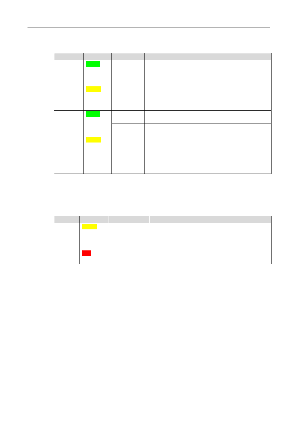
3.4.4 System Bus Indicators
The system bus LEDs are labeled Sys Bus.
LED
Color
Status
Description
A
Green
On
Physical and logical connection to the system bus
module in slot 1.
Blinking1 No physical connection to the system bus module in
slot 1.
Yellow
Blinking1
The physical connection to the system bus module in
slot 1 has been established.
No connection to a (redundant) processor module
running in system operation.
B
Green
On
Physical and logical connection to the system bus
module in slot 2.
Blinking1
No physical connection to the system bus module in
slot 2.
Yellow
Blinking1
The physical connection to the system bus module in
slot 2 has been established.
No connection to a (redundant) processor module
running in system operation.
A+B
Off
Off
Neither physical nor logical connection to the system
bus modules in slot 1 and slot 2.
Table 5: System Bus Indicators
3.4.5 I/O Indicators
The LEDs of the I/O indicator are labeled Channel.
LED
Color
Status
Description
Channel
1…12
Yellow
On
The corresponding channel is active (energized)
Blinking2
Channel fault
Off
The corresponding channel is not active (de-
energized)
Field
Red
Blinking2
Without function!
Off
Table 6: I/O Indicators

X-DO 12 01 3 Product Description
HI 801 023 E Rev. 5.00 Page 17 of 52
3.5 Product Data
General
Supply voltage
24 VDC, -15...+20 %, r
p
≤ 5 %,
PELV, SELV
Current input
max. 0.5 A
Current input of the module, all relay de-
energized
0.36 A (24.0 VDC)
Current input of the module, all relay
energized
0.48 A (24.0 VDC)
Electrical isolation of the channels
Yes
Operating temperature
0…+60 °C
Storage temperature
-40…+85 °C
Humidity max. 95 % relative humidity,
non-condensing
Type of protection
IP20
Dimensions (H x W x D)
310 x 29.2 x 230 mm
Weight
approx. 1.6 kg
Table 7: Product Data
Figure 4: Views

3 Product Description X-DO 12 01
Page 18 of 52 HI 801 023 E Rev. 5.00
Relay Outputs
Number of outputs (channels)
12, potential-free
Total switching current (all channels)
max. 30 A
Switching voltage
5...250 V
Switching current per channel
5 mA...4 A
Switching frequency
max. 4 Hz
Switching time
(energized contact closed)
10 ms
Reset time (de-energized contact
closed, without wiring)
3 ms
Bounce time for the energized contact
2 ms
Contact material
AgCuNi + 0.2…0.4 µm Au
Product life
Mechanical
Electrical
≥ 10 x 106switching operations
≥ 2.5 x 10⁵switching operations with ohmic full load
Table 8: Data of the Relay Outputs
Default
applications
Default
applications
Burner applications
in accordance with
VDE 0116, EN 50156
Switching operations
< 100 000
< 250 000
< 250 000
Switching capacity
DC
(non-inductive)
≤ 30 VDC
max. 4.00 A
max. 4.00 A
Fuse: 3.15 A
≤ 70 VDC
max. 1.25 A
max. 1.25 A
Fuse: 0.63 A
≤ 127 VDC
max. 0.50 A
max. 0.50 A
Fuse: 0.315 A
≤ 250 VDC
max. 0.28 A
max. 0.25 A
Fuse: 0.125 A
Switching capacity
DC
(inductive load
tau = L/R =
40 ms)
≤ 30 VDC
max. 0.80 A
max. 0.50 A
Fuse: 0.315 A
≤ 70 VDC
max. 0.32 A
max. 0.20 A
Fuse: 0.125 A
≤ 127 VDC
max. 0.19 A
max. 0.12 A
Fuse: 0.063 A
≤ 250 VDC max. 0.10 A max. 0.06 A Not specified
Switching capacity
AC
(non-inductive)
≤ 125 VAC
max. 4.00 A
max. 3.00 A
Fuse: 1.25 A
≤ 250 VAC max. 4.00 A max. 1.50 A Fuse: 0.63 A
Switching capacity
AC
cos φ > 0.5
≤ 125 VAC
max. 3.00 A
max. 1.20 A
Fuse: 0.63 A
≤ 250 VAC max. 1.50 A max. 0.60 A Fuse: 0.315 A
Table 9: Currents and Fuses
The table contains fuse values for burner applications and permissible maximum values for
standard applications.
Fuse protection is mandatory for burner application contact circuits and HIMA strongly
recommends employing fuse protection in standard applications.

X-DO 12 01 3 Product Description
HI 801 023 E Rev. 5.00 Page 19 of 52
3.5.1 Current Measurement
The module measures the current of each channel in intervals of 140 ms.
If two channels are interconnected in parallel, the current is divided across both channel. Only
the current actually flowing through each channels is measured.
Current measurement
Measurement interval
140 ms
Dead time after switching on
100 ms
Nominal current
0…4 A
Digital value per mA
10 000
Resolution
10-bit
Intrinsic error DC
+/-5 % of final value
Operating error DC
+/-7 % of final value
Form factor
1.2 for sine waves
Intrinsic error AC
+/-7 % of final value
Operating error AC
+/-9 % of final value
Table 10: Current Measurement per Channel

3 Product Description X-DO 12 01
Page 20 of 52 HI 801 023 E Rev. 5.00
3.6 Connector Boards
A connector board connects the module to the field zone. Module and connector board form
together a functional unit. Insert the connector board into the appropriate slot prior to mounting
the module.
The following connector boards are available for the module:
Connector board
Description
X-CB 011 01
Connector board with screw terminals
X-CB 011 02
Redundant connector board with screw terminals
X-CB 011 03
Connector board with cable plug
X-CB 011 04
Redundant connector board with cable plug
Table 11: Available Connector Boards
Accessories
Description
X-CB COVER 01
Cover hood.
Table 12: Connector Board Accessories
DANGER
Danger of electr
ic shock!
For connector boards with screw terminals: If the voltages exceed SELV, use the
X
-CB COVER 01 cover hoods or the X-FRONT COVER.
Observe all safety regulations!
Table of contents
Popular Relay manuals by other brands


Siemens
Siemens Solkor 7PG2114 Application guide

ABB
ABB Relion 615 series Applications manual

FANOX
FANOX D30 quick start guide

Rockwell Automation
Rockwell Automation Guardmaster Allen-Bradley 440R-S35001 Reference manual

Viessmann
Viessmann 5551 Operation manual

CD Automation
CD Automation Revo S user manual