Hinowa GOLD LIFT 1470 User manual

Technical Course
GOLD LIFT 1470

2
TABLE OF CONTENTS
1. INTRODUCTION..................................................................................4
Technical Data GOLD LIFT 1470 ..................................................................................5
2. FUNCTIONING AND SAFETY DEVICES OF THE MACHINE ...........................6
2.1 Functioning during the translation and when the machine is stabilized....7
2.2 Functioning during the aerial works ...................................................8
2.3 Emergency stop............................................................................ 11
2.4 Emergency descend. ..................................................................... 11
2.4.1 Electric emergency descend ................................................. 12
2.4.2 Emergency descend operated from the ground when the
machine is perfectly working ....................................................... 12
2.4.3 Emergency descend operated from the ground through the
manual pump in case of failure of all the systems conveying energy
..................................................................................................... 13
2.5 Manual pump ...............................................................................15
3. HYDRAULIC SYSTEM......................................................................... 16
FUNCTIONING OF THE UNDERCARRIAGE PART. ...................................... 17
FUNCTIONING OF THE AERIAL PART. .................................................... 18
FUNCTIONING OF THE FIRST AND SECOND ARM .................................... 21
FUNCTIONING OF THE BASKET LEVELLING. ........................................... 21
JIB FUNCTIONING .............................................................................. 22
4. ELECTRIC SYSTEM ..............................................................................
4.1 Feeding of the main lines F1 and 11 ............................................... 24
4.2 Starting the thermic engine .......................................................... 24
4.2.1 Starting the thermic engine from the ground .............................. 24
4.2.2 Starting the thermic engine from the basket ............................... 25
4.3 Starting the electric engine ............................................................ 25
4.4 Starter in the basket (gasoline only)................................................ 26
4.5 Operations of the platform ............................................................ 26
4.5.1 Translation and stabilization ..................................................... 26
4.5.2 Aerial work ............................................................................ 26
4.2.3 Jib ........................................................................................ 27
4.6 Emergency descend ..................................................................... 27
4.7 Load sensor setting ...................................................................... 27
4.5.1 Zero setting ........................................................................... 27
4.5.2 Setting the critical loads .......................................................... 28
4.8 Summary of the check operations of the electric system..................... 30
5. POSSIBLE INCONVENIENCES: CAUSES AND SOLUTIONS ............................. 31

3
4
1. INTRODUCTION
The aim of this booklet is to describe the Hinowa Gold Lift 1470 aerial platform at a technical level,
dealing with the safety devices of the machine, the electric and the hydraulic systems. The
description of the use of the machine is not trated in this text, but will be found in its use and
maintenance manual.
The numerical part of the name Gold Lift 1470 identifies, with the first two numbers the max.
working height of the machine in metres, with the second two numbers the max. working outreach
in decimetres.
The aerial platform is equipped with a hydraulic and electric system that interact to ensure the
safety of the machine in any situations. Below we are presenting the two systems, in particular
paying attention to their interactions.
We remind you that the correct position of the operator during the translation is inside the basket, in
the rear part. We have then the following scheme.
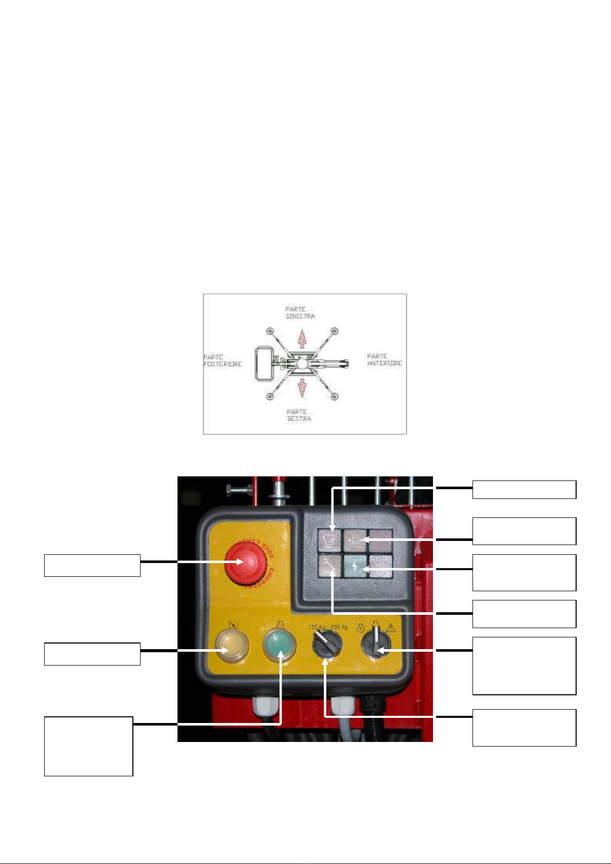
In the basket there is a control panel containing the lamps and the selectors to be used when
operating the machine.
EMERGENCY STOP
STARTER
THERMIC/ELE
CTRICENGINE
STARTER
LOAD SENSOR LAMP
TRANSLATION
CONSENT LAMP
LAMP FOR ELECTRIC
PANEL INPUT
(FEEDING)
LAMP OUTRIGGERS
ON THE GROUND
SELECTOR 1 THERMIC
– ELECTRIC ENGINE /
SAFETY DESCEND
SELECTOR 2
120/200 kg

5
Technical Data GOLD LIFT 1470
LOADING CAPACITY 200 kg LOADING CAPACITY 120
kg
PLATFORM’S HEIGHT (footboard) 10,58 m 11,94 m
MAX. WORKING HEIGHT 12,63 m 14,00 m
DIMENSIONS OF THE STANDARD BASKET 1330x694 H1100 mm
WORKING OUTREACH 5,16 m 6,24 m
MAX. WORKING OUTREACH 5,61 m 7,00 m
SLEWING (not continue) 300° 300°
LOADING CAPACITY 200 kg, 120 kg
MAX GROUND REACTION EACH OUTRIGGER 1330 daN
MAX GROUND PRESSURE EACH OUTRIGGER 1,9 daN/cm2
N° OPERATORS 2 1
N° OPERATORS WITH OPTIONAL 1 MAN BASKET 11
JIB-MOVEMENTS / 80° (+0°/-80°)
MAX. WORKING INCLINATION 1°/2,2%
MAX. STABILIZATION INCLINATION 10°
TOT. WEIGHT DURING TRANSPORT 1700 kg
THERMIC ENGINE HONDA GX270-9 CV-3000 rpm
HONDA GX390-13 CV-3000 rpm (Optional)
HATZ 1B30-7 CV-3000 rpm (Optional)
ELECTRIC ENGINE 1,5 kw/220V/50Hz 1500 rpm
1,5 kw/110V/50Hz 1500 rpm (Optional)
ELECTRIC SYSTEM VOLTAGE 12 V
PUMPS 2x3,15 cc
MAX. TRANSLATION SPEED (thermic engine) 1,4 km/h
MAX. TRANSLATION SPEED (thermic engine) with optional 2nd speed 1,4/2,8 km/h
PRESSURE OF TRANSLATION /STABILIZATION SYSTEMS 175 bar
AERIAL PART PRESSURE 180 bar
MAX. GRADEABILITY IN THE TRANSLATION DIRECTION 24°/53%
MAX. WIND SPEED 12,5 m/s
MAX. MANUAL FORCE ALLOWED 40 kg
TRACKED UNDERCARRIAGE’S WIDTH OPEN/CLOSED 780/1080 mm

6
2. FUNCTIONING AND SAFETY DEVICES OF THE MACHINE
The Gold Lift 1470 aerial platform is divided into two main parts:
1. Undercarriage part
2. Aerial part
If you use the machine during the translation or while it is stabilized, you operate the undercarriage
part; if you are working in altitude (height), then you operate the aerial part.
The operation of the two parts and their functioning is controlled by an electric panel consisting of
the assembly PLC + relay control; the relays are inside the electric components housing, on the left
side of the machine.

7
2.1 Functioning during the translation and when the machine is stabilized.
The translation and stabilization operations are controlled by the two valve-blocks located on the
undercarriage part
Both the translation and the stabilization are possible only if the machine is closed and aligned.
This condition is ensured by the two photoelectric cells on the rear part of the machine.
The first photoelectric cell is the type “sender-receiver”. The sender, located on the arm, sends a
signal. If the machine is closed and aligned, the signal is perceived by the receiver that is fixed to
the valve-block support and that sends a positive signal to the electric panel. The second
PHOTOELECTRIC
CELL 1
PHOTOELECTRIC
CELL 2

8
photoelectric cell is the “reflection” type. The component fixed on the arm sends a signal that, if the
machine is closed and aligned, is reflected by the retroreflector located on the valve-block support.
Then the signal comes back to the photoelectric cell on the arm, that sends a positive impulse to the
electric panel.
In order to be able to drive or stabilize the machine BOTH THE PHOTOELECTRIC CELLS
MUST SEND A POSITIVE SIGNAL TO THE ELECTRIC PANEL.
This condition is signalled by a lamp on the control panel (translation consent lamp).
The alignment of the machine is indicated by the two arrows on the valve-block support.
.
2.2 Functioning during the aerial works
The aerial operations are usually controlled by the valve-block in the basket.
There is also the possibility IN EMERGENCY SITUATIONS, to control the aerial part from the
ground through the valve-block located on the turret.

9
It is possible to move the aerial part only if the machine is stabilized and levelled (max 1°).
This condition is signalled by the 4 flashing lamps that are on, when the outriggers lay on the
ground and the machine is lifted.
The pressure of the discs on the ground is signalled by the 4 micrswitches located on the 4
outriggers, that are released by the cylinder rod when the disc touches the ground.
When all 4 outriggers send the signal to the electric panel, the machine is stabilized and a lamp
lights on the electric panel (lamp outriggers on the ground).
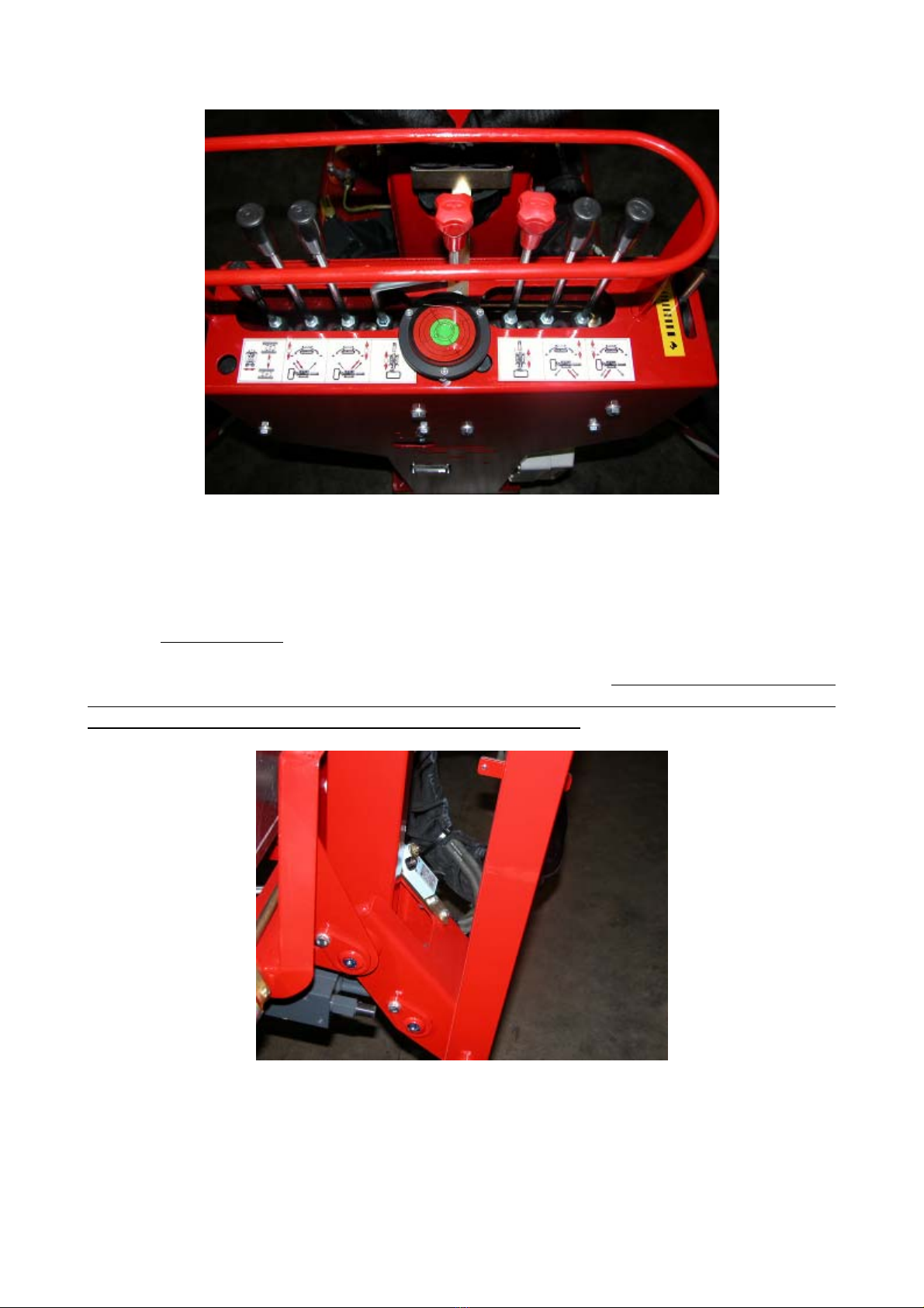
The levelling of the machine needs to be checked by the operator on the water level located near the
valve-block of the undercarriage part.
10
Bifore lifting the machines, the operator has to choose the working load through the 120/200kg
selector, located on the control panel.
The Gold Lift 1470 aerial platform can work in two ways:
200kg: on the basket two people are allowed, for a max. weight of 200kg. All the functions of the
machines are activated, but the JIB movements. To work in this way, it is necessary that the JIB
ARM IS COMPLETELY CLOSED. This condition is controlled by a microswitch located in the
lower part of the JIB arm. When the arm is closed, the micro-switch sends a signal to the electric
panel allowing the 200kg load only up to max. 12 working metres. In case you chose the 200kg.
way and the Jib arm was not completely closed, the red flashing lamp on the control panel “load
sensor lamp” would light, emitting an intermittent acoustic signal.
120kg: only 1 person is allowed in the basket, for a max. weight of 120kg. All the functions of the
machine are activated, up to a working height of 14m.
NOTE: the selection of the working way must be done only when the machine is closed.

11
One more device controlling the movements of the aerial part of the machine is the electronic load
sensor. A sensor located under the basket controls the load and checks that it is lower than the max.
one foreseen for the machine and selected by the operator.
In case the max. allowed weight was overcome (120kg o 200 kg), the load sensor under the basket
sends a signal to the circuit board located near the basket, and the machine immediately stops. On
the control panel the red flashing lamp “load sensor lamp” lights, emitting an intermittent acoustic
signal.
2.3 Emergency stop
The Gold Lift aerial platform is equipped with 2 emergency stop buttons: one is on the control
panel and the other one is on the undercarriage part, near the valve-block that controls the aerial
part.
If you use the emergency buttons to stop the machine when the arm is closed, an intermittent
acoustic signal warns that the engine key is in the ON position.
2.4 Emergency descend.
The machine has been designed taking into account possibile emergency situations such as
mechanic failures, electric failures, illness of the operator, etc. In all these cases it is possibile to
act/intervene on the machine both from the basket and from the ground in order to bring the
machine back in the transport configuration, or to be able to assist the operator/s inside the basket.
Below are indicated the intervention procedures.
NOTE: We remind you that while the machine is working, the presence of people of the staff on the
ground is compulsory.
12
2.4.1 Electric emergency descend.
The emergency descend procedure can be done from the basket only if the elctric system of the
machine is in good order; do the following operations:
-keep the manual “selector 1” on the control panel pushed
-operate the usual arm descend controls until you reach the desired height;
- leave the manual “selector 1” on the control panel pushed
Since the descend is due to the force of gravity, it is of course not possible to obtain the swing
movement of the platform and the movements of the telescopic arm; then the basket sinks vertically
at a distance from the rotation centre, that depends on the configuration the machine had when the
emergency situation happened.
The basket rotation can be operated by the operator who is on the ground through the slew ring
screw, opposite to the hydraulic motor. Anyway, in order to move the machine, you need to move
the rotation lever on the valve-block either in the basket or on the ground.
In the model 1470 when you are using the emergency descend, the jib cylinder cannot be activated;
this means that when the arm is completely down, the basket is at about 1,8 m height. In this case,
in order to help the person in the basket, it is necessary to use an external tool (for example a
ladder).
2.4.2 Emergency descend operated from the ground when the machine is perfectly working.
This emergency descend is to be used only in case of:
- illness of the operator inside the basket.
The only reason to allow the use of the emergency descend from the ground is to help the operator/s
bringing the basket down, near the ground level; any other use is forbidden.
To operate the emergency descend in the above mentioned conditions, do as follows:
a) Move the deviator for the valve-block selection, from the valve-block in the basket to the
valve-block on the undecarriage.
13
b) On the valve-block on the undercarriage, singularly move the levers that control the arms,
until the operator is on the ground.
NOTE: in the model 1470, when you are using the emergency descend, the jib cylinder cannot be
activated, then when the arm is completely down, the basket is at about 1,8 m height. In this case, in
order to help the operator, you have to use an external tool (for example a ladder).
2.4.3 Emergency descend from the ground through the manual pump in case of failure of all the
systems conveying energy.
This emergency descend is to be used only in case of:
- failure of the electric system of the machine, when it is not possible to make any emergency
manoeuvres from the basket;
The only reason to allow the use of the emergency descend from the ground is to compensate a
failure in the system and bring back the basket on the ground; any other use is forbidden.
The emergency descend from the ground can be made using the hydraulic manual pump.

14
In order to move the basket, you need to pump the oil manually and at the same time to use the
controls for the arms movements located on the undercarriage.
It is absolutely forbidden to make manoeuvres that are different from the above mentioned ones,
such as to open the telescopic arm, to move the jib (only for the model 1470), the outriggers, and in
general all the manoeuvres that could cause a loss of stability of the machine.
In order to operate the emergency descend in the above mentioned conditions, do as follows:
Case 1: there is tension when you turn the ignition key to the ON position and when the emergency
descend buttons are not on:
1. move the deviator towards the manual pump, in the position corresponding to the arms
movement;
2. move the selection deviator from the valve-block in the basket to the valve-block on the
undercarriage;
3. move the manual pump and at the same time move the levers of the arms movements
singularly, until the operator is on the ground.
Case 2: There is no tension or the emergency stop buttons are on:
remove the protection cap from the blue safety electrovalve near the electric motor
1. energize the mechanical activation of the electrovalve, pushing and turning the golden knob
near the electrovalve coil.
15
3. put the deviator on the manual pump in the position that corresponds to the arms
movements.
4. move the selection deviator from the valve-block in the basket to the valve-block on the
undercarriage;
5. move the manual pump and at the same time move the levers of the arms movements
singularly, until the operator is on the ground.
2.5 Manual pump
The manual pump conveys the pressured oil, to make manoeuvres in case of emergency due to
failures of the main hydraulic system.
The manual pump is equipped with a manual deviator that allows choosing to move either the two
right outriggers (Position 1) or the two left outriggers and the aerial part of the structure (Position
2).
The outrigger operations are allowed only if the electric system hasn’t got failures and the ignition
key is in the ON position.
In case of failure of the electric system, if you need to move the outriggers you have to move the
deviator aerial part-undercarriage part manually, using the mechanical commutator that is delivered
together with the machine in the electric components’ housing (see picture).

16
As soon as the emergency operations have been completed, don’t forget to remove the mechanical
commutator of the deviator and to restore the standard configuration of the deviator. The presence
of the mechanical commutator of the deviator during the work jeopardizes the safety of the
machine, causing possible dangerous situations.
It is allowed to manoeuver the outriggers in emergency situations, only in case of failure of the
machine and in case you needed to close the outriggers to transport the machine.
3. HYDRAULIC SYSTEM
For the description of the Gold Lift hydraulic system we refer to the attachment 1. The numbers in
brackets indicate the components of the hydraulic circuit.
The circuit of the Gold Lift is fed through three pumps groups:
1. Group (4) connected with the thermic engine (2) - 2 3cc/rev pumps set at 3000rpm-.
2. Group (4) connected with the electric engine (3) - 2 3cc/rev pumps set at 1500rpm-.
3. Emergency manual pump (1). Since this pump is unique, a deviator has been put on the delivery
line (1) to select in which of the two deliveries to convey the flow.
The deliveries of the three pumps groups are conveyed through a collector (5) to two main delivery
hoses A and B. Six unidirectional valves prevent the pressured oil of one group from coming back
to the tank, through one of the other two groups.
The two main delivery hoses A and B go into the black electric deviator (6) located near the slew
ring, on the side of the electric engine.
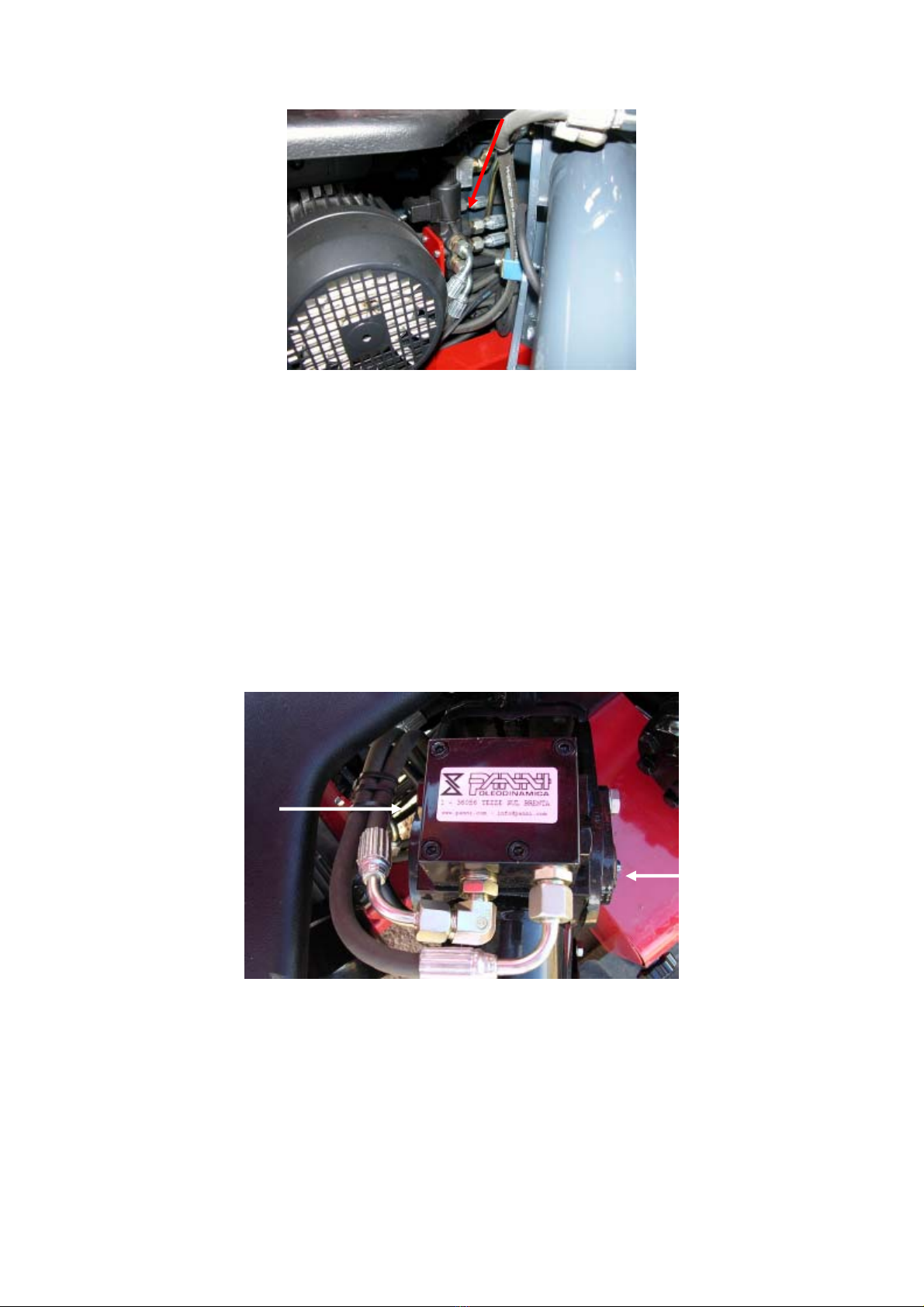
17
With the deviator you choose to convey the oil to the valveblock either of the undercarriage part or
of the aerial part. If the coil is not energized, the delivery A is conveyed to the aerial part, the
delivery B is conveyed to the tank. The aerial part uses only one pump. This condition happens
when the machine IS NOT ALIGNED. On the contrary, if the machine is ALIGNED, the deviator
is excited and the oil is conveyed to the undercarriage part.
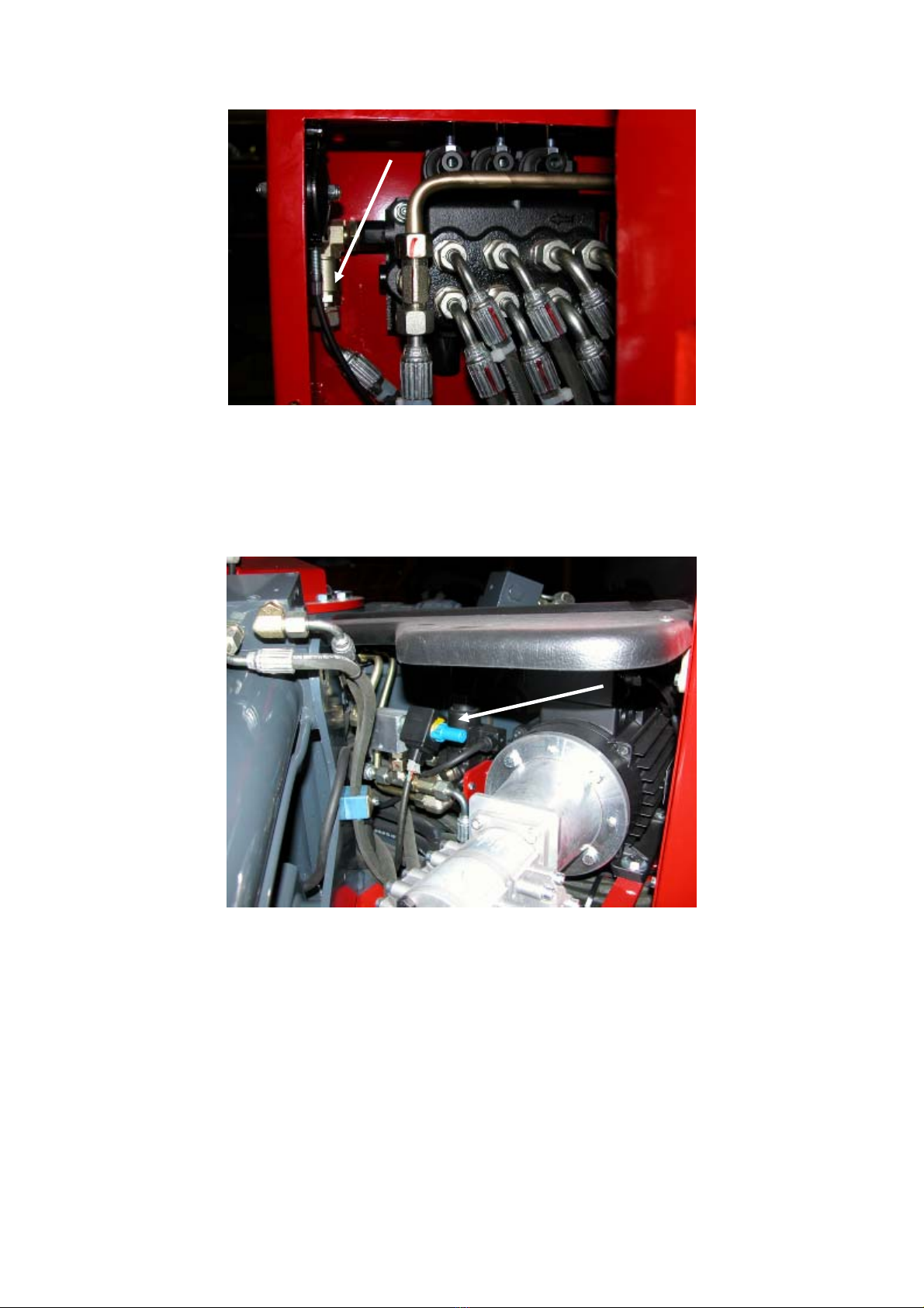
FUNCTIONING OF THE UNDERCARRIAGE PART.
The oil of the deliveries A and B is conveyed to the two valve-blocks 9 and 10, through which the
two hydraulic drive motors are controlled (14), to the 4 outriggers (12) and to the undercarriage’s
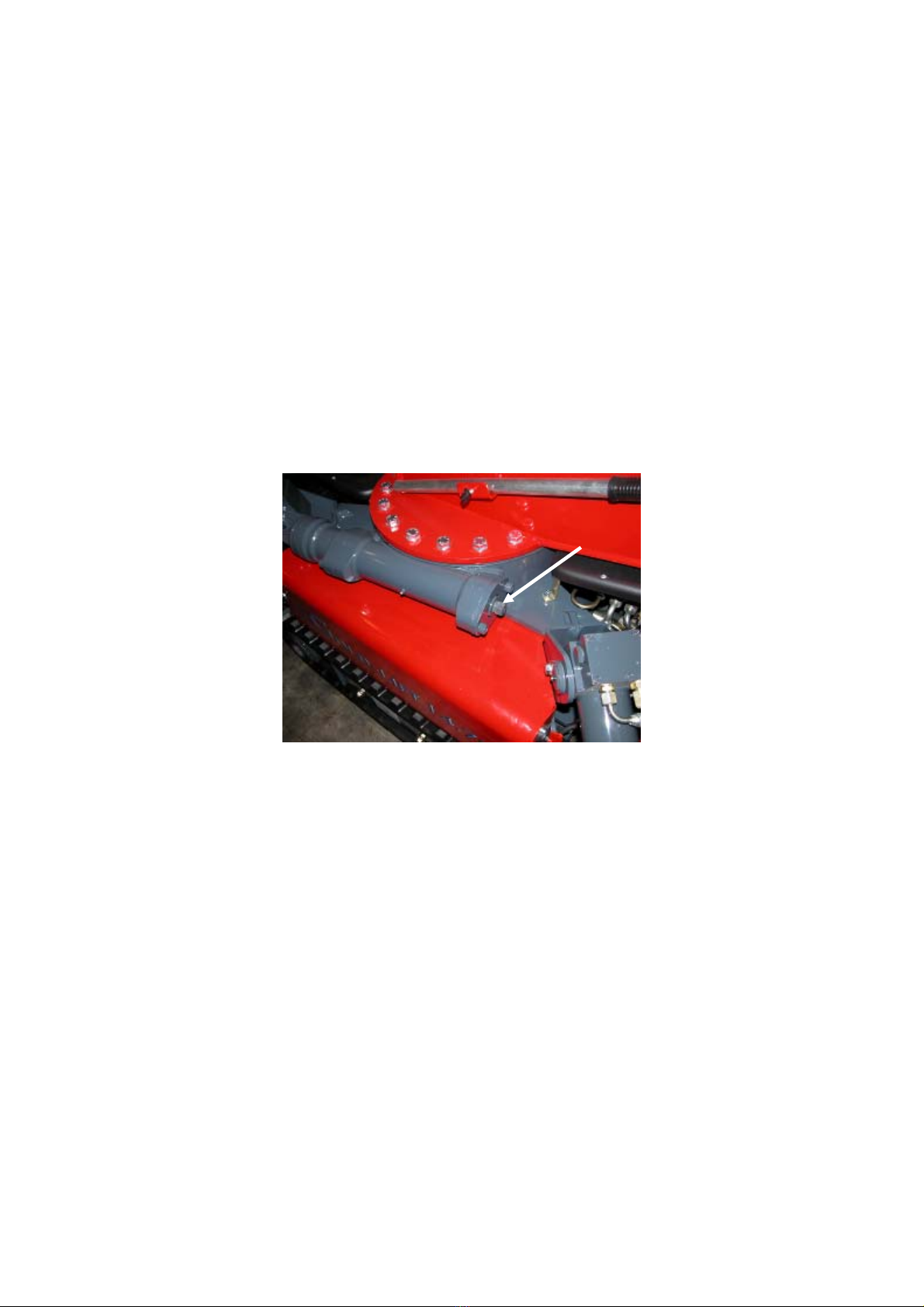
widening cylinders (11). On each of the 4 outriggers are mounted two piloted block valves in series,
on the piston side, flanged near the pin that fixes the cylinder to the structure.
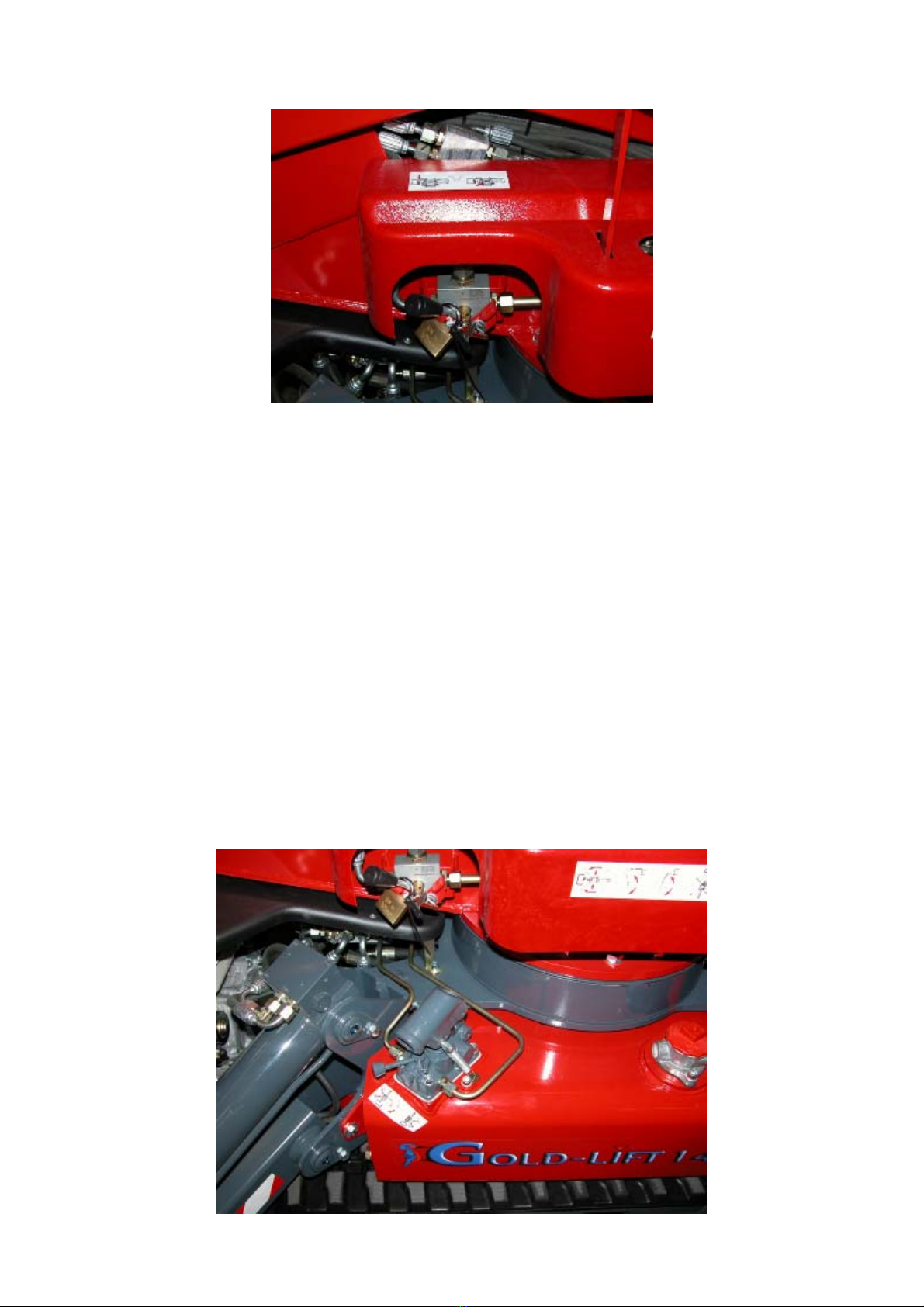
From the right valve-block (10) comes a hose (carry over connection) that goes together with the
delivery of the valve-blocks in the aerial part. The function of this connection is to allow the first
movement of the aerial part, that disalignes or open the machine and commutes the deviator 6,
directly feeding the aerial part. A unidirectional valve located on a compact curve at the exit of the
valve-block, prevents the pressured oil from coming back to the tank through the valve-block 10,
when using the aerial part.
18
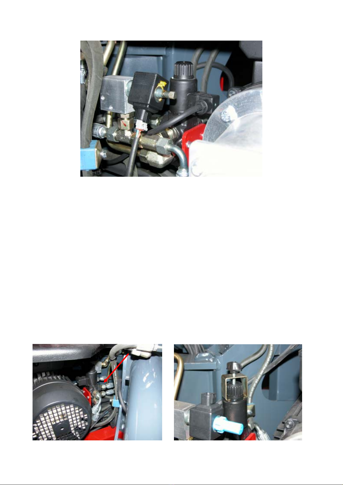
FUNCTIONING OF THE AERIAL PART.
The delivery B that goes to the valve-blocks of the aerial part (17 and 32) is connected in parallel
with a two-ways / two positions electrovalve connected with the tank and usually open. (8). See
2.4.3
If this electrovalve is NOT POWERED, the oil is conveyed to the tank, preventing the movement of
the aerial part. This condition happens when:
1. The machine is not stabilized
2. The load sensor is alarmed
3. You select the 200kg way and the Jib is not completely closed.
On the contrary, when the machine is stabilized, with a load which is lower than its limit and in the
proper functioning way, you can go up. To excite the electrovalve 8, you need to close the
connection to the tank.
The delivery hose goes then into a deviator (16) that sends the oil to the valve-block in the basket or
to the valve-block on the undercarriage part.
19
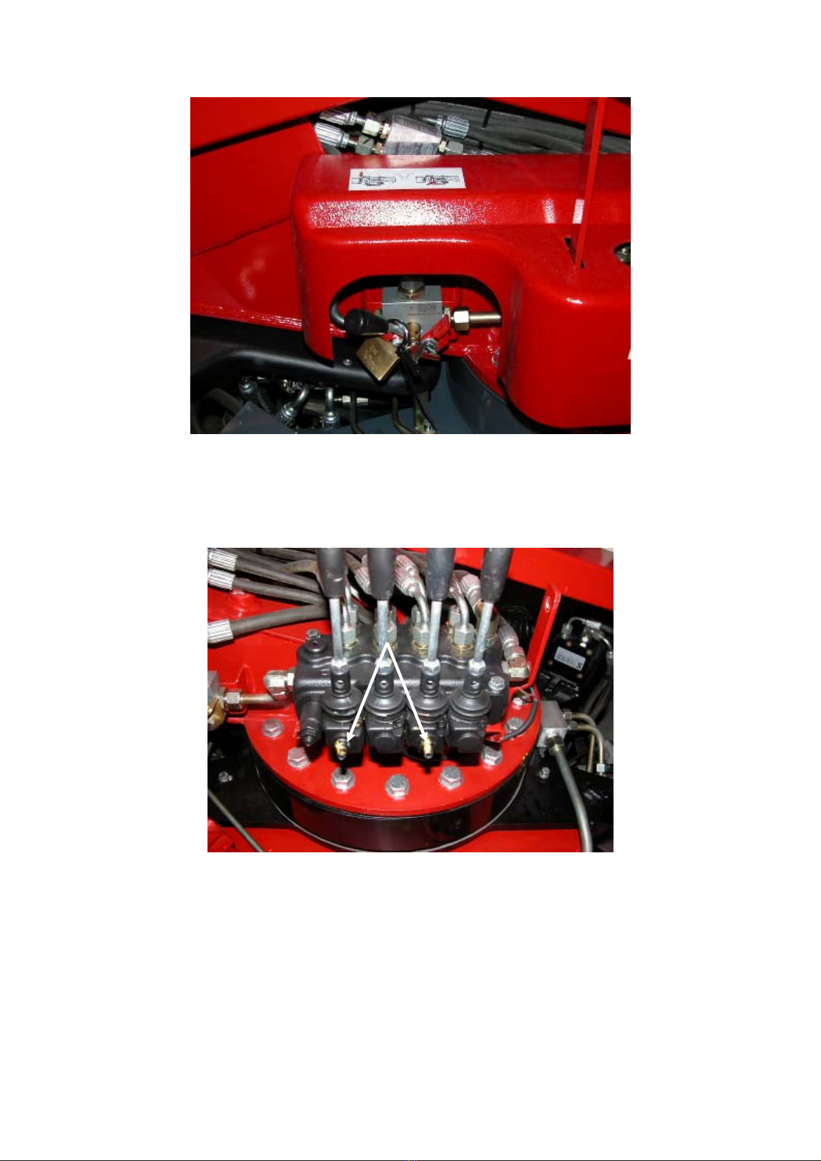
The valveblocks convey the oil to the cylinders that move the machine. The setting of the machine
speeds is made by registers at the sides of the valveblock, that limit the spools’ run bypassing some
of the oil to the tank. Such settings cannot be altered, since the speed of the machine is set by law.
The connections of the hoses coming from the valveblocks both on the undercarriage and in the
basket, are usually positioned on the balancing valves.

20
The extension and the rotation are exceptions; in this case the aluminium blocks make the
connection.
Balancing valves are flanged on all cylinders; these work both as block valves, limiting the
descending speed and as anti-shock valves (20; 21; 23; 27; 24; 31). Some of these valves also
include the electrovalve for the emergency descend (see 2.4.1) (20; 21; 23). On the contrary, the
valve of the basket levelling cylinder is double (31).
The manufacturer sets these valves and they must not be altered (tampered with). An action on
these valves for example releasing the setting screw, can increase the descend speed and decrease
the setting of the anti-shock valve, with a consequent big danger for the operator.
EXTEN
S
I
O
N
ROTATION
Table of contents


