Hirschmann Manitex vSCALE D3 User manual

vSCALE D3
Operating console
SLI system
Manitex Telescopic Crane Contents
Safety instructions 1
Product description 2
Installation / Wiring 3
Commissioning 4
Operation 5
Maintenance / Repair 6
Appendix 7
User manual
Issue B - 03/2012
This document has the order no.
50-700-19-2001_422175_en
Pub Mtx p/n: 7600004-023
Date: April 2012
For System: 4800850-001

TABLE OF CONTENTS
1Safety instructions...........................................................................................6
1.1 EC conformity declaration ............................................................................6
2Product description..........................................................................................7
2.1 Product identification ....................................................................................7
2.2 Use for the intended purpose.......................................................................8
2.3 Overview of functional elements...................................................................9
3Installation and wiring....................................................................................10
3.1 Installation...................................................................................................10
3.1.1 Surface mounting.................................................................................10
3.1.2 Recessed mounting .............................................................................11
3.2 Electrical connection...................................................................................14
3.2.1 Central connector –X1 .........................................................................15
3.2.2 Ethernet connection.............................................................................16
3.2.3 Camera connection (optional)..............................................................16
4Commissioning...............................................................................................17
4.1 Switching device on and off........................................................................17
4.2 Adjust SLI to latest set-up status................................................................19
4.3 Zero point adjustment of sensors...............................................................24
4.3.1 Zero point adjustment of the main boom angle sensor........................26
4.3.2 Zero point adjustment, slewing angle sensor.......................................27
4.3.3 Sensor adjustment, main boom length sensor.....................................28
4.3.4 Zero point adjustment of inclination sensor (X/Y) on superstructure...29
5Operation.........................................................................................................30
5.1 Functional elements....................................................................................31
5.2 SLI main menu............................................................................................32
5.2.1 Function keys (soft keys) .....................................................................33
5.2.2 Warning lights / acoustic alarm............................................................34
5.3 SLI setup.....................................................................................................35
5.4 Illustrated overview of crane configurations...............................................36
© 2012 Hirschmann Automation and Control GmbH · Mobile Machine Control Solutions · www.hirschmann.com 2/59
50-700-19-2001_422175_en (Manitex)_Rev_B.doc / 2012-03-13 / Issue B / rk.

5.5 Working area monitoring.............................................................................37
5.5.1 Height monitoring.................................................................................38
5.5.2 Radius monitoring................................................................................39
5.5.3 Luffing angle monitoring.......................................................................40
5.5.4 Slewing angle monitoring.....................................................................41
5.6 Fade in live video image (optional).............................................................42
5.7 Inclination display .......................................................................................43
5.8 Load taring..................................................................................................44
5.9 Switching off alarm .....................................................................................44
5.10 Info menu....................................................................................................45
5.10.1 Status of digital inputs..........................................................................46
5.10.2 Readings of CAN bus sensors.............................................................47
5.10.3 Status of digital outputs........................................................................48
5.11 Service menu..............................................................................................49
6Maintenance and Repair................................................................................50
7Appendix .........................................................................................................51
7.1 Technical data ............................................................................................51
7.2 Error codes table........................................................................................52
VERSION OVERVIEW
Issue Date Description Editor
A 2012-03-08 First issue for Manitex telescopic crane application
Translation from the original german manual:
Issue A (2012-02-24) - rk
R. Konopka
B 2012-03-13 Corrections R. Konopka
Hirschmann Automation and Control GmbH
Hertzstr. 32-34
76275 Ettlingen
Phone +49 7243 709-0
Germany
© 2012 Hirschmann Automation and Control GmbH · Mobile Machine Control Solutions · www.hirschmann.com 3/59
50-700-19-2001_422175_en (Manitex)_Rev_B.doc / 2012-03-13 / Issue B / rk.

Introduction
INTRODUCTION
This manual is a component of the equipment or system supplied by Hirschmann Automation and
Control GmbH. Keep this manual in a safe place and ensure that it is available to all users.
About this manual
The contents of this manual are subject to change. Hirschmann Automation and Control GmbH
does not provide any guarantee for this material, including the associated guarantee regarding
marketability and suitability for certain intended purposes. Hirschmann Automation and Control
GmbH accepts no liability for errors in the contents of the manual or for direct or indirect damage in
connection with the provision and use of the manual.
Liability disclaimer
This manual is protected by copyright. All rights reserved. The manual may not be duplicated,
reproduced or translated into another language, either wholly or partly, without the prior written
permission of Hirschmann Automation and Control GmbH.
Copyright notice
The rendition of common names, trade names, trademarks etc. in this documentation should not be
construed to mean that such names, even without special identification, are free in the sense of
trademark and trademark protection legislation and hence usable by anyone.
Trademarks
This device / system is intended exclusively for the tasks described in this manual. Any other use
shall be construed as being inappropriate. The manufacturer accepts no liability for damage caused
by inappropriate or impermissible use. This device / system may only be used if it is in perfect
technical condition.
Use for the intended
purpose
Only appropriately qualified personnel may work with this device / system, i.e. persons:
Qualification of the
operating personnel who are familiar with the operation or installation and commissioning
who know the current regulations for the prevention of accidents
© 2012 Hirschmann Automation and Control GmbH · Mobile Machine Control Solutions · www.hirschmann.com 4/59
50-700-19-2001_422175_en (Manitex)_Rev_B.doc / 2012-03-13 / Issue B / rk.

Introduction
Marking of notices
Dangers and other important notices are marked as follows in this user manual:
WARNING
Warning of direct threat of personal injury and damage to property.
Instructions on precautions to avert the danger.
CAUTION
Warning of dangerous situations. Also warns of damage to property.
Instructions for averting the danger.
IMPORTANT
Warning of possibly damaging situation for the product.
Instructions for avoiding the possibly damaging situation.
NOTE
Usage instructions and information, but no dangerous situation.
HINT
Supplementary comments and recommendations for the user.
© 2012 Hirschmann Automation and Control GmbH · Mobile Machine Control Solutions · www.hirschmann.com 5/59
50-700-19-2001_422175_en (Manitex)_Rev_B.doc / 2012-03-13 / Issue B / rk.

Safety instructions
1 Safety instructions
WARNING
Imminent threat of personal injury and damage to property due to incorrect system settings!
The correct adjustment of the SLI to the current set-up status is essential for the correct
function of the system and of the crane.
The SLI can only operate correctly if all settings are entered correctly according to the
current set-up status during the SETUP procedure.
The settings can only be carried out by operators who are completely familiar with the
operation and functions of the crane and the SLI.
The correctness of these settings must be guaranteed before starting the crane operations!
IMPORTANT
Connection to the wrong power supply will cause damage to the device.
The device may only be connected to a DC voltage source of 10 V to 30 V!
1.1 EC conformity declaration
The technical design and construction of the vSCALE D3 console corresponds to requirements of
the EMC directive 2004/108/EC and therefore carries the CE symbol.
The device complies with the following harmonised standards:
EN 12895:200, EN 13309:2010, EN ISO 14982: 2009
The full conformity declaration is available from the manufacturer on request.
© 2012 Hirschmann Automation and Control GmbH · Mobile Machine Control Solutions · www.hirschmann.com 6/59
50-700-19-2001_422175_en (Manitex)_Rev_B.doc / 2012-03-13 / Issue B / rk.

Product description
2 Product description
The vSCALE D3 console is the operable component of the programmable safe load indicator,
referred to below as the “SLI”. The SLI detects the readings from different sensors and recognises
crane overload statuses depending on further parameters. Visual and acoustic signals alert the
user of the overload status.
The SLI comprises:
a cSCALE S6 central control unit
the vSCALE D3 display and operating console
various sensors for detection of readings
The control unit, sensors and operating consoles are installed in suitable positions onto or inside
the crane.
The vSCALE D3 console is used for:
programming and inputting operating parameters
displaying the current crane operating data
This user manual contains information about installation, commissioning, operation and sensor
calibration and about repairs and maintenance.
Scope of manual
2.1 Product identification
The type plate carries the unique identification of the operating console. It is located on the back of
the device.
Please ensure you make a note of all the information on your type plate for queries about this
product.
Type plate
(Example)
© 2012 Hirschmann Automation and Control GmbH · Mobile Machine Control Solutions · www.hirschmann.com 7/59
50-700-19-2001_422175_en (Manitex)_Rev_B.doc / 2012-03-13 / Issue B / rk.

Product description
2.2 Use for the intended purpose
The vSCALE D3 is the operable component of the safe load indicator (SLI).
The SLI detects a crane overload status depending on various parameters.
The crane driver is warned well before the onset of an overload status via visual and acoustic
warning signals.
Although the system has signal outputs to switch off the crane movements which increase the load
moment, this power-off should only be effective with corresponding external wiring.
Although the system incorporates functions for monitoring adjustable geometrical limit values with
visual and acoustic warnings and a relay output in the event of limit values being exceeded, the
system cannot be used as an operational limit switch.
The crane driver is responsible for the safe operation of the crane.
© 2012 Hirschmann Automation and Control GmbH · Mobile Machine Control Solutions · www.hirschmann.com 8/59
50-700-19-2001_422175_en (Manitex)_Rev_B.doc / 2012-03-13 / Issue B / rk.

Product description
2.3 Overview of functional elements
1 TFT colour display
2 Function keys F1 - F12
3 Light sensor and status displays (LED)
4 Rotary control (encoder) with pushbutton function
5 Function key (SYSTEM) for system settings (not used here)
6 Function key (Home) for return to SLI main menu
7 Function key (Esc) for return or abort (not used here)
8 Front- USB 2.0 interface (use for service purposes)
© 2012 Hirschmann Automation and Control GmbH · Mobile Machine Control Solutions · www.hirschmann.com 9/59
50-700-19-2001_422175_en (Manitex)_Rev_B.doc / 2012-03-13 / Issue B / rk.

Installation and wiring
3 Installation and wiring
This chapter contains instructions for mounting and installation of the console.
For the electrical wiring of the system and the console, please refer to the relevant connection and
wiring diagram, which is not part of this manual.
3.1 Installation
The console is intended for vertical surface mounting or recessed mounting. Depending on
installation type, corresponding installation accessories are required which may be supplied with
the device depending on the version type.
3.1.1 Surface mounting
For surface mounting you will require the optionally available installation adapter and the RAM
Mount articulated mounting.
RAM Mount
(Art. no. 320795)
Installation
adapter
(Art. no. 608464)
4 pcs.
screw M5x12
(Art. no. 300990)
4 pcs.
washer 5.3
(Art. no. 320795)
3 pcs.
screw M5x12
(Art. no. 300990)
3 pcs.
washer 5.3
(Art. no. 320795)
ball head 38mm (1.5“)
(part of RAM Mount)
© 2012 Hirschmann Automation and Control GmbH · Mobile Machine Control Solutions · www.hirschmann.com 10/59
50-700-19-2001_422175_en (Manitex)_Rev_B.doc / 2012-03-13 / Issue B / rk.

Installation and wiring
3.1.2 Recessed mounting
An installation frame, which is available as an accessory, is provided for recessed mounting in
operating panels or instrument panels.
Installation frame: Art. no. 608465
NOTE
Please note that the material thickness of the operating panel may not exceed 10 mm!
Installation frame
4 off M5 x
(see table for length)
Material
thickness Screw length
1…3 mm M5 x 12
4…6 mm M5 x 16
7…10 mm M5 x 20
© 2012 Hirschmann Automation and Control GmbH · Mobile Machine Control Solutions · www.hirschmann.com 11/59
50-700-19-2001_422175_en (Manitex)_Rev_B.doc / 2012-03-13 / Issue B / rk.

Installation and wiring
The dimensions for the cut-out in the operating panel can be taken from the following sketch:
Cut-out dimensions
On request you can also print out the templates (last page in this manual).
Template
© 2012 Hirschmann Automation and Control GmbH · Mobile Machine Control Solutions · www.hirschmann.com 12/59
50-700-19-2001_422175_en (Manitex)_Rev_B.doc / 2012-03-13 / Issue B / rk.

Installation and wiring
4 x M5 screws, DIN EN ISO 4762 (DIN 912) and matching spacers are used for mounting of the
installation frame.
Installation
Installation frame
IMPORTANT
Console could be damaged by use of screws of the wrong length and excessive torque!
Note the screw length information in the following overview.
The maximum screw tightening torque is 1 Nm.
The length of the screws depends on the material thickness of the operating panel:
Material thickness 1 to 3 mm: M5 x 12 4 to 6mm: M5 x 16 7 to 10 mm: M5 x 20
4 off
spacers
Length:
Material thickness
+0.5 mm
4 off M5 screws,
DIN EN ISO
4762 (DIN 912)
Length:
Depending on
material thickness
secure screws with e.g. Loctite 243!
max. ti
g
htenin
g
tor
q
ue 1 Nm!
© 2012 Hirschmann Automation and Control GmbH · Mobile Machine Control Solutions · www.hirschmann.com 13/59
50-700-19-2001_422175_en (Manitex)_Rev_B.doc / 2012-03-13 / Issue B / rk.
Installation and wiring
3.2 Electrical connection
The electrical wiring for the system and the console can be found in the current connection and
wiring diagram for your crane. It is not included in this manual.
CAUTION
Danger of electrical short-circuits.
Switch off all systems before commencing with the installation work!
IMPORTANT
Connection to the wrong power supply will cause damage to the device.
The device may only be connected to a DC voltage source of 10 V to 30 V!
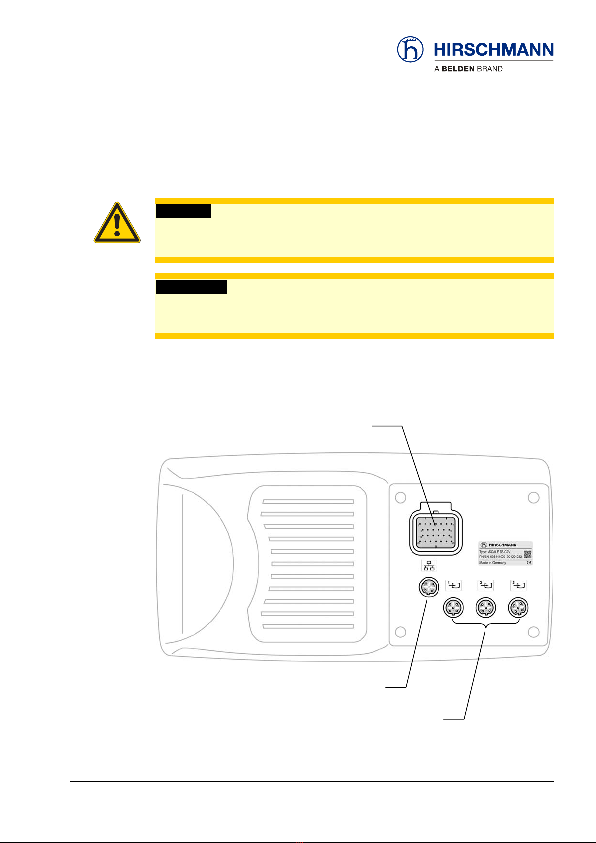
Connections and interfaces can be found on the back of the device. You need to remove this first if
using the installation adapter.
Camera connector 1-3
Central connector -X1
Ethernet connection
Back of device
© 2012 Hirschmann Automation and Control GmbH · Mobile Machine Control Solutions · www.hirschmann.com 14/59
50-700-19-2001_422175_en (Manitex)_Rev_B.doc / 2012-03-13 / Issue B / rk.

Installation and wiring
3.2.1 Central connector –X1
The central connector –X1 contains terminals for the power supply, ignition, grounds,
CAN-Bus (1 and 2), USB, RS232 and further signals.
Connector kit: 1x connector, 26x crimp contacts, 26x dummy plug Art. no. 536276
Matching counter-
connector parts Crimping tool: special tool Art. no. (on request)
Connector overview
1 Vcc +8…36 V (terminal 30) 14 USB D-
Pin assignation 2 Ignition (terminal 15) 15 USB D+
3 GND (terminal 31) 16 RS232 RxD
4 Chassis GND 17 RS232 TxD
5 n.c. 18 RS232 GND
6 n.c. 19 AI/DI 3 (optional)
7 n.c. 20 AI/DI 1 (optional)
8 CAN1 high 21 AI/DI 2 (optional)
9 CAN1 low 22 AI/DI 4 (optional)
10 CAN2 high 23 SERV_ENABLE
11 CAN2 low 24 DO 3
12 USB Vcc (+5 V) 25 DO 1
13 USB GND 26 DO 2
© 2012 Hirschmann Automation and Control GmbH · Mobile Machine Control Solutions · www.hirschmann.com 15/59
50-700-19-2001_422175_en (Manitex)_Rev_B.doc / 2012-03-13 / Issue B / rk.

Installation and wiring
3.2.2 Ethernet connection
There is an Ethernet interface available for programming purposes.
Patch cable, 5m, M12, 4-pin, <-> RJ45 Art. no. 325900
Matching counter-
connector parts
Connector overview
1 TD+
Pin assignation 2 RD+
3 TD-
4 RD-
3.2.3 Camera connection (optional)
Three video interfaces are available for integrating video signals.
Round connector M12, 5-pin, PIN, B-coded, according to EN 61076-2-101.
Cable available on request.
Matching counter-
connector
Connector overview
1 Video Signal +
Pin assignation 2 Camera Control
3 Camera +
4 Camera -
5 Video Signal GND
© 2012 Hirschmann Automation and Control GmbH · Mobile Machine Control Solutions · www.hirschmann.com 16/59
50-700-19-2001_422175_en (Manitex)_Rev_B.doc / 2012-03-13 / Issue B / rk.

Commissioning
4 Commissioning
This chapter contains information, advice and instructions for commissioning the device.
4.1 Switching device on and off
The load limiting device has no on/off switch. The console automatically switches on after
connecting the power supply and control voltage (ignition, terminal 15)
After boot-up the following appears on the display:
Device has been switched off
for longer than 2 hours Device has been switched back on
within 2 hours:
Display after
boot-up:
Carry out SETUP procedure next!
(See chapter 4.2)
If the crane configuration has not changed within
the last 2 hours, check displayed configurations.
If OK, confirm.
The SLI menu is then displayed.
© 2012 Hirschmann Automation and Control GmbH · Mobile Machine Control Solutions · www.hirschmann.com 17/59
50-700-19-2001_422175_en (Manitex)_Rev_B.doc / 2012-03-13 / Issue B / rk.

Commissioning
In the event of a system malfunction an error code is displayed in the bottom right of the display:
System malfunction?
The error codes and what they mean are explained in the error codes table in chapter 7.2.
The device is not ready for operation until all faults have been rectified and no error codes are
displayed.
If the console is not started as described, please contact your nearest service department.
© 2012 Hirschmann Automation and Control GmbH · Mobile Machine Control Solutions · www.hirschmann.com 18/59
50-700-19-2001_422175_en (Manitex)_Rev_B.doc / 2012-03-13 / Issue B / rk.

Commissioning
4.2 Adjust SLI to latest set-up status
The SLI must be adjusted to the current crane set-up status by completing the full SETUP
procedure after start-up (device has been switched off for longer than 2 hours) and after any
change to the crane configuration. The process is step-by-step and is menu-guided. Operation is
with the rotary control.
SETUP procedure
The system is not ready to operate until the full SETUP procedure has been completed.
WARNING
Imminent threat of personal injury and damage to property due to incorrect system settings!
The correct adjustment of the SLI to the current set-up status is essential for the correct
function of the system and of the crane.
The SLI can only operate correctly if all settings are entered correctly according to the
current set-up status during the SETUP procedure.
The settings can only be carried out by operators who are completely familiar with the
operation and functions of the crane and the SLI.
The correctness of these settings must be guaranteed before starting the crane operations!
Depending on the inputs during the SETUP procedure and on various sensor values, the system
automatically determines the corresponding operating mode with the associated lifting capacity
table. The operating mode used by the system at any one time is displayed as a code in the status
row:
Selecting operating
mode
Operating
mode code
The settings made during the SETUP procedure are saved for 2 hours. When the system is
switched back on, e.g. after a short interruption to the work, the settings need simply to be checked
and confirmed.
Saving settings
The process for setting the SLI to the current crane set-up status (SETUP procedure) includes the
following steps:
Process
Selecting the outrigger and support base
Selection of the boom configuration and fly jibs
Selection of the man basket / load block
Entering the number of rope reevings
Selection of hoisting winch
Overview of inputs
© 2012 Hirschmann Automation and Control GmbH · Mobile Machine Control Solutions · www.hirschmann.com 19/59
50-700-19-2001_422175_en (Manitex)_Rev_B.doc / 2012-03-13 / Issue B / rk.

Commissioning
Operation is with the rotary control:
Operation
Optionally press to confirm.
Back to previous menu option with
Calling up SETUP procedure from the SLI main menu:
Start SETUP
All inputs must correspond to the current set-up status of the crane!
Selection:
Crane operation with outriggers
Select outriggered
or on wheels
Crane operation on wheels
© 2012 Hirschmann Automation and Control GmbH · Mobile Machine Control Solutions · www.hirschmann.com 20/59
50-700-19-2001_422175_en (Manitex)_Rev_B.doc / 2012-03-13 / Issue B / rk.
Table of contents
Other Hirschmann Music Mixer manuals


