Hirschmann iSCOUT expert compact User manual

iSCOUT
expert compact
Graphics console
Operator's Manual
Issue 8/2008 Rev. C
This document is listed under Order No.
50 650 19 0201e (LinkBelt278)
Contents
General Information
Important Notes
System Description
Configuration Setup
Inspection checks
before start-up
Service and Maintenance
Troubleshooting
Appendix

Operation Manual iSCOUT expert compact (Link-Belt 278)
© 2008 HIRSCHMANN Automation and Control GmbH · Branch Office Ettlingen · eMail: [email protected] · www.hirschmann-usa.com 2
50 650 19 0201e_Rev C (LinkBelt278).doc / 2008-08-18 / Rev. C / rk
TABLE OF CONTENTS
1. General Information.................................................................3
2. Important Notes........................................................................4
3. System Description..................................................................5
3.1 System Function.........................................................................6
3.2 Operator's Console ....................................................................7
3.3 Displays and operating elements ...............................................8
3.4 Description of the status symbols ............................................14
4. Configuration Setup...............................................................15
4.1 Interactive operating mode setup.............................................16
4.2 Quick adjusting the reeving or selecting the hoist....................22
4.3 Programming geometrical limits ...............................................24
4.3.1 Radius limitation ......................................................................25
4.3.2 Tip height limitation ..................................................................27
4.3.3 Boom angle limitation ...............................................................29
4.3.4 Slewing angle limitation / Virtual wall definition........................31
Slewing angle limitation............................................................31
Virtual wall definition ................................................................33
5. Pre-operational Inspection....................................................36
5.1 Operation .................................................................................38
6. Service and Maintenance ......................................................39
6.1 Info / Service Menus.................................................................40
7. Troubleshooting.....................................................................44
7.1 General Notes ..........................................................................44
7.2 Malfunction Table.....................................................................45
Appendix: Menu overview calibration menus ..............................50
Appendix: Important Instructional Notes......................................53

System Description
© 2008 HIRSCHMANN Automation and Control GmbH · Branch Office Ettlingen · eMail: [email protected] · www.hirschmann-usa.com 3
50 650 19 0201e_Rev C (LinkBelt278).doc / 2008-08-18 / Rev. C / rk
1. GENERAL INFORMATION
The purpose of the iFLEX5 load moment limitation and control system with iSCOUT expert compact
console (hereafter referred to as LMI) is to provide the crane operator with important information
necessary for the operation of the crane within the areas of operation specified by the manufacturer.
The LMI uses a variety of different sensors to monitor different crane functions and communicates the
crane performance data to the crane operator on a continuous basis. This data changes constantly in
connection with the crane movements.
If the crane nears its safe load limit, the system will warn the crane operator by means of both acous-
tic and optical signals. In addition, as soon as the crane reaches an unauthorized operating status, all
crane movements will be switched off that would increase the load moment on the crane.
The PAT iFLEX5 system uses a graphics operator interface, the functionality of which is determined
by the crane manufacturer. The selection of the programmed functions is considerably simplified by
the use of symbols.
The load moment limitation and control system based on the PAT iFLEX5 is made up of main com-
ponents that are connected via a CAN bus.
The manufacturer reserves the right to modify the contents of this manual without notice. Hirschmann offers no guarantee
whatsoever for this material, including guarantees with reference to commercial availability and suitability for particular appli-
cations. Hirschmann shall not be liable for errors contained herein or for identical or consequential damages in connection
with the furnishing, performance, or use of this manual. This manual is protected by copyright. All rights reserved. The man-
ual may not be copied, reproduced or translated into another language, neither whole nor in part, without advance written
authorization from Hirschmann.

System Description
© 2008 HIRSCHMANN Automation and Control GmbH · Branch Office Ettlingen · eMail: [email protected] · www.hirschmann-usa.com 4
50 650 19 0201e_Rev C (LinkBelt278).doc / 2008-08-18 / Rev. C / rk
2. IMPORTANT NOTES
The LMI is an operating aid that warns the crane operator of imminent overloading or of the approach
of the hook block, hook ball, or load to the boom head, in order to avoid possible property damage or
injury to personnel.
The device is not, nor is it intended to be, a substitute for good operator judgment and/or experience,
nor does it remove the need for utilizing only recognized safe procedures during crane operations.
The crane operator continues to bear ultimate responsibility for safe operation of the crane.
He must ensure that he fully understands and follows the displayed notes and instructions
in their entirety.
Before beginning crane operations, the crane operator must carefully read and understand
the entire manual in order to ensure that he is aware of the operation and limitations of both
the LMI and the crane itself.
Proper functioning is dependent upon proper daily inspection and observation of the oper-
ating instructions set forth in the manual.
The LMI is not able to provide aid to the crane operator unless it has been properly adjusted
and unless the correct load capacity chart and the correct operating code have been en-
tered for the respective rigging configuration. The accuracy of the LMI settings must be
guaranteed before beginning crane work in order to avoid damage to property and severe
or even fatal injuries to personnel.
This system can be equipped with an external key-operated switch located in the crane op-
erator's cab. This key-operated switch overrides control lever function switch-off by the LMI
or by the hoist limit switch system. This switch may only be used during emergency situa-
tions, and even then only by authorized personnel. Failure to observe these instructions
could result in damage to property and severe or even fatal injuries to personnel.
The LMI cannot perform correctly unless it has been properly adjusted. The prerequisite for
this is making conscientious and correct entries during the set-up procedure, in accor-
dance with the actual configuration of the crane. The accuracy of the LMI settings must be
ensured before beginning crane work in order to avoid damage to property and severe or
even fatal injuries to personnel.

System Description
© 2008 HIRSCHMANN Automation and Control GmbH · Branch Office Ettlingen · eMail: [email protected] · www.hirschmann-usa.com 5
50 650 19 0201e_Rev C (LinkBelt278).doc / 2008-08-18 / Rev. C / rk
3. SYSTEM DESCRIPTION
The PAT load moment limitation and control system consist of an iFLEX5 central unit, an iSCOUT
expert compact CAN console and various sensors for collection the measured values.
Fig. 1: Components of the LMI system with iFLEX5
The system operates on the principle of reference/real comparison. The actual value is compared
with the calculated reference values and evaluated by the system. An overload warning signal is trig-
gered on the display and operating console once limit values are reached. All crane movements that
increase the load moment are switched off at the same time.
The crane-specific data specified by the manufacturer, such as load capacity charts, boom weights,
centers of gravity and dimensions, are stored in the central data memory. This data is the reference
information used to calculate the operating conditions.
The boom angle is registered by means of an angle sensor that is mounted on the boom. The crane
load is determined indirectly with the aid of force and angle sensors.

System Description
© 2008 HIRSCHMANN Automation and Control GmbH · Branch Office Ettlingen · eMail: [email protected] · www.hirschmann-usa.com 6
50 650 19 0201e_Rev C (LinkBelt278).doc / 2008-08-18 / Rev. C / rk
3.1 SYSTEM FUNCTION
Upon switching on, the system starts with an automatic test of the LMI system, of lamps
and audible alarm. During the test, the LC (liquid crystal) display shows the start screen.
If the system was turned off for more than the maximum time, the setup configuration
must be entered after the system test. (⇒chapter 4)
First, the operating mode is determined by a step-by-step review of the rigging states.
Next, input of the reeving.
Now the LC display shows all inputs and awaits acknowledgment or cancelling.
Upon acknowledgment of the inputs the system is ready for operation.
In the event of a disruption, a corresponding error code "E##" will appear on the Data dis-
play (1). (> refer to error code table)

System Description
© 2008 HIRSCHMANN Automation and Control GmbH · Branch Office Ettlingen · eMail: [email protected] · www.hirschmann-usa.com 7
50 650 19 0201e_Rev C (LinkBelt278).doc / 2008-08-18 / Rev. C / rk
3.2 OPERATOR'S CONSOLE
The console has several functions:
•Entries into the LMI system made by the crane operator
(mode of operation, number of reevings, etc.)
•Important data and information displays during crane operation
•Input of geometry limit values and cut-off if exceeding limits
•Call-up and display of system information for operator and service personnel
The operating console is located in the operator's cab in plain view of the crane operator. All displays
have background illumination for enhanced ease of recognition. The console contains various operat-
ing elements as well as a multifunction LC display, all of which are described in detail in Chapter 3.3.
The background illumination of the operating elements and the LC display is manually adjustable in
accordance with present light levels.
System Description
© 2008 HIRSCHMANN Automation and Control GmbH · Branch Office Ettlingen · eMail: [email protected] · www.hirschmann-usa.com 8
50 650 19 0201e_Rev C (LinkBelt278).doc / 2008-08-18 / Rev. C / rk
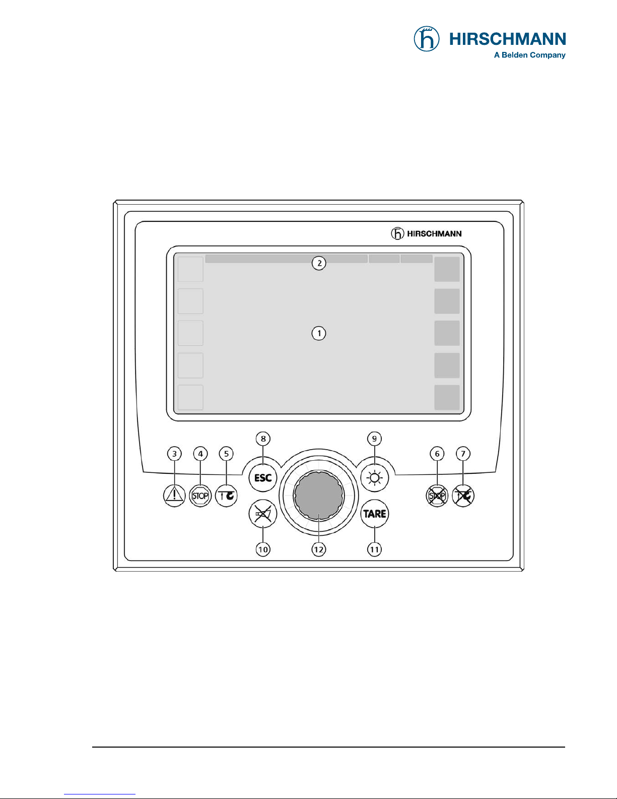
3.3 Displays and operating elements
Figure 1 shows the display and operating elements of the iSCOUT expert compact console.
The numbers in this illustration correspond to the numbers of the following functional characteristics
for each element:
Fig. 2
1 Data display
2 Utilization display field (bar graph)
3 Prewarning lamp (load moment)
4 Overload warning light (load moment)
5 "Hoist limit" warning light (A2B)
6 "LMI override" warning light
7 "Hoist limit override" warning light
8 "ESC" pushbutton (to main menu)
9 "Settings > Brightness" pushbutton
10 "Alarm off" pushbutton
11 "TARE" pushbutton
12 Rotary selection wheel with push button
System Description
© 2008 HIRSCHMANN Automation and Control GmbH · Branch Office Ettlingen · eMail: [email protected] · www.hirschmann-usa.com 9
50 650 19 0201e_Rev C (LinkBelt278).doc / 2008-08-18 / Rev. C / rk
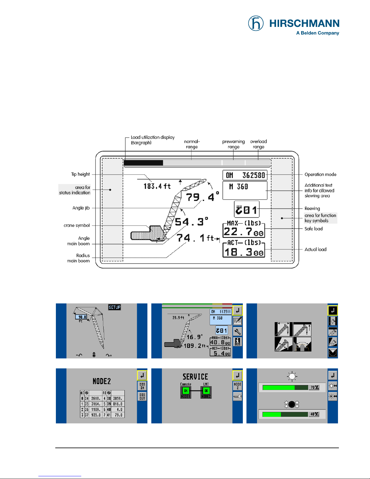
(1) Data display
The Data display (1) is a 6.5" LC color graphics display with background illumination which shows
required data such as load values, geometry and crane data, symbols, etc., depending on the respec-
tive operating status.
Normal LMI display: (Illustration in black/white)
Other display examples:
Set-up Menu (mode of operation) Standard LMI screen Limits Menu
iNFO Menu (CAN Node 2) Service Menu (Bus Information) Brightness Setting Menu
A detailed description of the symbols and displays can be found both in the individual chapters and in the Appendix to this
manual.

System Description
© 2008 HIRSCHMANN Automation and Control GmbH · Branch Office Ettlingen · eMail: [email protected] · www.hirschmann-usa.com 10
50 650 19 0201e_Rev C (LinkBelt278).doc / 2008-08-18 / Rev. C / rk
(2) Utilization display (bar graph)
The Utilization display (bar graph) indicates how much of the per-
mitted load (nominal moment) is currently being utilized. The load
display also undergoes constant alteration because the nominal
moment changes continuously during lifting operation.
The bar graph is filled with various colors:
green: "safe" range (0...90% of the nominal moment)
yellow: "pre-warning" range (90...100% of the nominal moment)
red: "overload range" (>100% of the nominal moment)
(3) "Load moment prewarning" light
This yellow prewarning light comes up when the load on the crane
amounts to 90% - 100% of the respective nominal carrying load,
which indicates that an overload situation is immediately pending.
For the crane operator, this means that the crane work can
continue only with the greatest amount of caution.
(4) "Overload" warning light
This red Overload warning light indicates to the crane operator that
an overload condition has occurred. It lights up when the crane
load has reached 100% of maximum load carrying capacity permit-
ted for the current operating status. The acoustic alarm sounds.
The load-moment-increasing crane movements are switched off at
the same time.

System Description
© 2008 HIRSCHMANN Automation and Control GmbH · Branch Office Ettlingen · eMail: [email protected] · www.hirschmann-usa.com 11
50 650 19 0201e_Rev C (LinkBelt278).doc / 2008-08-18 / Rev. C / rk
(5) "Hoist limit" warning light
This red warning light lights up when the hoist limit switch contacts
open, i.e. when a hoist limit situation has occurred. The acoustic
alarm sounds and load-moment-increasing crane movements are
switched off at the same time.
A hoist limit situation occurs when the hook block comes
into contact with the boom head. The danger exists in such
situations that the hoist rope will break, causing the load to
fall. A hoist limit situation could arise from the load being
pulled against the boom head or from the boom being ex-
tended or lowered without the hoist rope being spooled off
the drum(s).
(6) "Load limit device (LMI) override" warning light
This red warning light lights up when the switch-off function of the
LMI system has been manually overridden.
(7) "Hoist limit switch override" warning light
This red warning light lights up when the switch-off function of the
hoist limit switch has been manually overridden.
(8) "ESC (Escape)" key
Push button for returning to the normal LMI display
NOTE

System Description
© 2008 HIRSCHMANN Automation and Control GmbH · Branch Office Ettlingen · eMail: [email protected] · www.hirschmann-usa.com 12
50 650 19 0201e_Rev C (LinkBelt278).doc / 2008-08-18 / Rev. C / rk
(9) "Brightness setting" pushbutton
The brightness and thus the legibility of the data display and the
buttons can be adjusted at any time with this pushbutton.
(10) "Buzzer off" key
The acoustic alarm can be suppressed by pressing this pushbut-
ton, although not before the alarm has sounded a minimum of 5 s.
The alarm will sound again after approximately 10 s if the cause of
it being triggered is still present.
The acoustic alarm sounds in the following situations:
System test, overload condition, imminence of a hoist limit situation (when the
hoist limit switch function is registered by the LMI system), disruption of the LMI
system, or presence of operating errors recognized by the system.
(11) "TARE" key
The "TARE" key is for the purpose of outputting the net load on the
Actual load display. The net load is the current load minus the load
hoisting equipment and the hook block. The "TARE" pushbutton
must be pressed before the hoisting process is initiated.
After the button is actuated, the Current Load display is set to zero (tared). After
the load has been raised, the Current Load display will then show the net load
(payload). As soon as the working radius (by angle or radius modification) is modi-
fied, the display shows again the current load and the taring function is completed.
Note: The current load includes the hook block, the hoist rope and all of the load
lifting tackle. The net load is the current load on the hook without load lifting
tackle. Display errors can be caused by the effects of environmental influences
such as wind on the boom or the load.

System Description
© 2008 HIRSCHMANN Automation and Control GmbH · Branch Office Ettlingen · eMail: [email protected] · www.hirschmann-usa.com 13
50 650 19 0201e_Rev C (LinkBelt278).doc / 2008-08-18 / Rev. C / rk
(12) Rotary selection wheel with pushbutton
This central rotary selection wheel is used to navigate within the
menu structure.
At first select the desired soft key symbol .
By pressing the button of the rotary wheel the marked function is
carried out.
select
symbol
▼LMI main screen (1st level of function keys)
< show info screens
< start operation mode setup
< set geometrical limits
< start TARE function
< switch to 2nd level of function keys
▼LMI main screen (2nd level of function keys)
< back to the previous menu
< show LMI value screen
< show service menu (code required)
< show CAN-bus menu

System Description
© 2008 HIRSCHMANN Automation and Control GmbH · Branch Office Ettlingen · eMail: [email protected] · www.hirschmann-usa.com 14
50 650 19 0201e_Rev C (LinkBelt278).doc / 2008-08-18 / Rev. C / rk
3.4. Description of the status symbols
Symbol for LMI error (in connection with fault code)
Symbol for bus error
Hoist limit switch has come into action (A2B)
Back-up battery for console RAM memory is low.
Ask field service to replace lithium battery 3V on printed circuit board.
Back-up battery for iFLEX5 RAM memory is low.
Ask field service to replace lithium battery 3V on printed circuit board.
Symbol radius limitation
•continuously visible:
radius limitation active
•blinking:
range limits exceeded
(⇒see chapter 4.3.1)
Symbol height limitation:
•continuously visible:
height limitation active
•blinking:
height limit exceeded
(⇒see chapter 4.3.2)
Symbol boom angle limitation:
•continuously visible:
boom angle limitation active
•blinking:
angle limits exceeded
(⇒see chapter 4.3.3)
Symbol slewing angle limitation:
•continuously visible:
slewing angle limitation active
•blinking:
slewing angle limits exceeded
(⇒see chapter 4.3.4.1)
Symbol work area definition:
•continuously visible:
work area definition active
•blinking:
work area limits exceeded
(⇒see chapter 4.3.4.2)
Programming
© 2008 HIRSCHMANN Automation and Control GmbH · Branch Office Ettlingen · eMail: [email protected] · www.hirschmann-usa.com 15
50 650 19 0201e_Rev C (LinkBelt278).doc / 2008-08-18 / Rev. C / rk
4. Configuration SETUP
It is necessary to setup the system by entering the respective mode of configuration every time the
crane structure is modified.
The SLI cannot perform correctly unless it has been properly adjusted. The prerequisite for
this is making conscientious and correct entries during the setup procedure, in accordance
with the actual configuration of the crane. The accuracy of the SLI settings must be ensured
before beginning crane work in order to avoid damage to property and severe or even fatal
injuries to personnel.
The correct setting is of utmost importance for the proper functioning of the system and the
crane.
Therefore, only operators who are thoroughly familiar with the crane and the operation of
the system should execute this configuration procedure.
The setup procedure is cancelled any time by pressing key (8) "ESC". The system, however, is only
ready for operation, if the procedure has been completed and the inputs have been confirmed.
During the programming procedure the Load Moment Prewarning Light (3) and the Load Moment
Limit Light (4) will light up and the crane movements will be interrupted.
If the system is turned off all adjustments remain stored. When turning the system on again these
adjustments can be acknowledged by merely pressing the "OK" key in the confirmation screens (pro-
vided that the crane configuration has not been modified)
Programming
© 2008 HIRSCHMANN Automation and Control GmbH · Branch Office Ettlingen · eMail: [email protected] · www.hirschmann-usa.com 16
50 650 19 0201e_Rev C (LinkBelt278).doc / 2008-08-18 / Rev. C / rk
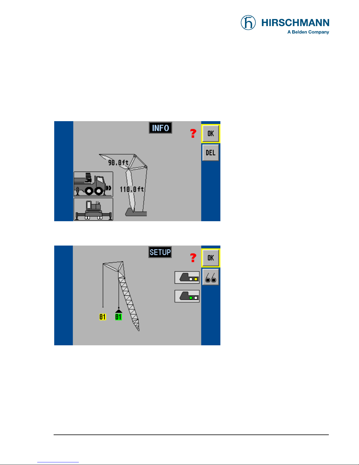
•Confirmation screens:
In this menu screens, the operator is prompted to confirm the previous made entries if crane configu-
ration has not been modified since last turning off the system.
Check the displayed values before confirming them!
< OK, if all entries are correct
< DELETE entries, renew setup
< Quick change hoist selection
If "OK" was selected the next menu appears:
< OK, if all entries are correct
< Renew pickpoint and reeving
selection
The procedure is completed after this confirmation, and the crane menu is displayed.

Programming
© 2008 HIRSCHMANN Automation and Control GmbH · Branch Office Ettlingen · eMail: [email protected] · www.hirschmann-usa.com 17
50 650 19 0201e_Rev C (LinkBelt278).doc / 2008-08-18 / Rev. C / rk
4.1 Interactive operating mode setup
It is necessary to setup the system by entering the respective mode of operation every time the crane
structure is modified.
The system will temporarily interrupt the movements of the crane during the programming procedure.
The correct setting is of utmost importance for the proper functioning of the system
and the crane. Therefore, only operators who are thoroughly familiar with the crane
and the operation of the system should execute the setting of the system
according to the operating configuration of the crane.
The LMI programming procedure consists of the following steps (interactive operation):
•setting the boom type configuration
•specify jib / selecting the pick point
•setting the outrigger configuration
•setting the counterweight configuration
•setting the hoist
•setting the reevings
•confirmation of the programming procedure
For easy operation, the computer guides the operator through the procedure step by step.
Calling up the function:
Select the soft function key and actuate the rotary wheel button (from the LMI screen)

Programming
© 2008 HIRSCHMANN Automation and Control GmbH · Branch Office Ettlingen · eMail: [email protected] · www.hirschmann-usa.com 18
50 650 19 0201e_Rev C (LinkBelt278).doc / 2008-08-18 / Rev. C / rk
< Start operation mode setup
The following illustrations define the symbols appearing on the display during the setup procedure.
Not all symbols will be shown, depending on the crane type and the answers to the questions.
•Setting boom type configuration
If "DEL " was selected:
select boom type with the rotary
wheel and click wheel to confirm
main
boom tip exten-
sion hammer-
head hammerhead
tip extension
jib luffer luffer +fixed jib
Programming
© 2008 HIRSCHMANN Automation and Control GmbH · Branch Office Ettlingen · eMail: [email protected] · www.hirschmann-usa.com 19
50 650 19 0201e_Rev C (LinkBelt278).doc / 2008-08-18 / Rev. C / rk
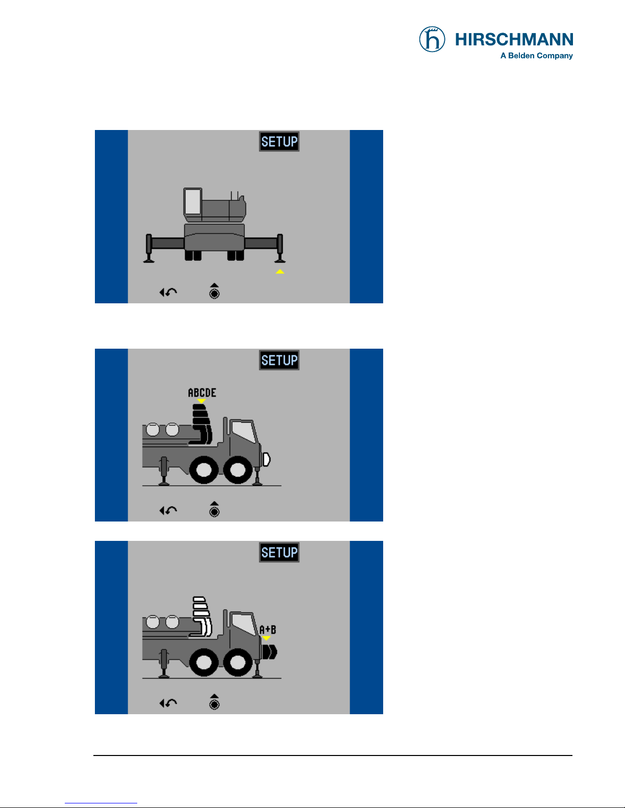
•Setting outrigger type
select base with the rotary wheel
and click wheel to confirm
•Setting counterweight configuration
select counterweight with the rotary
wheel and click wheel to confirm
or:
select counterweight with the rotary
wheel and click wheel to confirm

Programming
© 2008 HIRSCHMANN Automation and Control GmbH · Branch Office Ettlingen · eMail: [email protected] · www.hirschmann-usa.com 20
50 650 19 0201e_Rev C (LinkBelt278).doc / 2008-08-18 / Rev. C / rk
•Specify boom / Setting the hoist configuration and reevings (example luffer)
Luffing Jib length selection:
select luffer length with the rotary
wheel and click wheel to confirm
Luffing Boom length selection:
select luffer length with the rotary
wheel and click wheel to confirm
select first pick point to config-
ure:
select pick point with the rotary
wheel and click wheel to confirm
Table of contents
Other Hirschmann Music Mixer manuals


