Hirschmann PAT IFLEX5 User manual

HIRSCHMANN
P/N 031-300-190-147 REV E- 11/12/2008
LOAD MOMENT INDICATOR
iFLEX5
vertical/horizontal console
OPERATOR’S MANUAL


© Hirschmann Rev. E 11/12/08 190147_E
NOTICE
PAT America, Inc. makes no warranty of any kind with regard to this material, including, but not limited
to, the implied warranties of merchantability and/or its fitness for a particular purpose.
PAT America, Inc. will not be liable for errors contained in this manual or for incidental or
consequential damages in connection with the furnishing, performance, or use of this manual. This
document contains proprietary information, which is protected by copyright, and all rights are reserved.
No part of this document may be photocopied, reproduced, or translated to another language without
the prior written consent of PAT America, Inc.
PAT America, Inc. reserves proprietary rights to all drawings, photos and the data contained therein.
The drawings, photos and data are confidential and cannot be used or reproduced without the written
consent of PAT America, Inc. The drawings and/or photos are subject to technical modification
without prior notice.
All information in this document is subject to change without notice.
MANUAL REVISIONS
REV DATE NAME DESCRIPTION
- 2/22/02 MO ECN 02-64
A 11/11/02 CH ECN 02-278
B 05/19/03 SB ECN 03-065
C 02/22/05 MS ECN 05-041
D 01/06/06 SB ECN 05-217
E 11/12/08 WG ECN 08-179
© 2006 Hirschmann, Chambersburg, PA 17201, USA


Operator's Manual iFLEX5
© Hirschmann Rev. E 11/12/08 190147_E
TABLE OF CONTENTS
1GENERAL INFORMATION.............................................................................................................1
2WARNINGS.....................................................................................................................................1
3SYSTEM DESCRIPTION ................................................................................................................2
3.1 SYSTEM FUNCTION ........................................................................................................................4
3.2 OPERATING CONSOLE ...................................................................................................................5
3.3 CONTROL IDENTIFICATION..............................................................................................................5
4CONFIGURATION SETUP ........................................................................................................... 11
4.1 LMI SETUP PROCEDURE..............................................................................................................11
4.2 QUICK SETTING OF THE REEVING.................................................................................................15
4.3 QUICK HOIST LINE SELECTION.....................................................................................................16
5OPERATION .................................................................................................................................17
5.1 LIMIT SETTING.............................................................................................................................20
5.1.1 Slewing Angle Limitation / Work Area Definition...........................................................21
5.1.2 Tip Height Limitation ........................................................................................................26
5.1.3 Boom Angle Limitation.....................................................................................................27
5.1.4 Radius Limitation..............................................................................................................29
5.1.5 Wind Speed .......................................................................................................................30
5.2 INFO CRANE CONFIGURATION ......................................................................................................31
5.3 DISPLAY CONTRAST CONTROL.....................................................................................................32
6PRE-OPERATION INSPECTION AND CALIBRATION VERIFICATION.....................................33
6.1 MACHINES WITH ONLY A MAIN HOIST............................................................................................33
6.2 MACHINES WITH MAIN AND AUXILIARY HOISTS .............................................................................33
6.3 INSTALLATION OF ANTI TWO-BLOCK RETAINER IN LOCKING POSITION ..........................................34
6.4 REMOVAL AND STORAGE OF THE ANTI TWO-BLOCK RETAINER.....................................................34
6.5 PRE-OPERATION INSPECTION AND CALIBRATION VERIFICATION ....................................................35
7SERVICE AND MAINTENANCE...................................................................................................36
8TROUBLESHOOTING ..................................................................................................................37
8.1 GENERAL ....................................................................................................................................37
8.2 MALFUNCTION TABLE ..................................................................................................................37
8.3 OPERATING ERRORS ...................................................................................................................38
9APPENDIX A: DETAILED SYMBOL EXPLANATION OF BOOM EXTENSIONS .......................40
10 APPENDIX B:DETAILED SYMBOL EXPLANATION OF COUNTERWEIGHT OPTIONS.......41


General Information
© Hirschmann Rev. E 11/12/08 190147_E
1
1 GENERAL INFORMATION
The PAT Load Moment Indicator1(LMI) has been designed to provide the crane operator with
the essential information required to operate the machine within its design parameters.
Using different sensing devices, the Load Moment Indicator monitors various crane functions
and provides the operator with a continuous reading of the crane’s capacity. The readings
continuously change as the crane moves through the motions needed to make the lift.
The LMI provides the operator with information regarding the length and angle of the boom,
working radius, rated load and the total calculated weight being lifted by the crane.
If non permitted conditions are approached, the Load Moment Indicator will warn the operator
by sounding an audible alarm, lighting a warning light and locking out those functions that may
aggravate the crane’s condition.
2 WARNINGS
The LMI is an operational aid that warns a crane operator of approaching overload conditions
and of overhoist conditions that could cause damage to equipment and personnel.
The device is not, and shall not, be a substitute for good operator judgment, experience and use
of accepted safe crane operating procedures.
The responsibility for the safe crane operation shall remain with the crane operator who shall
ensure that all warnings and instructions supplied are fully understood and observed.
Prior to operating the crane, the operator must carefully and thoroughly read and understand
the information in this manual to ensure that he knows the operation and limitations of indicator
and crane.
Proper functioning depends upon proper daily inspection and observance of the operating
instructions set forth in this manual. Refer to Section 6. Pre-Operation Inspection and
Calibration Verification of this handbook.
The LMI can only work correctly, if all adjustments have been properly set. For correct
adjustment, the operator has to answer thoroughly and correctly all questions asked
during the setup procedure in accordance with the real rigging state of the crane. To
prevent material damage and serious or even fatal accidents, the correct adjustment
of the LMI has to be ensured before starting the crane operation.
1LOAD MOMENT: generally the product of a force and its moment arm; specifically, the product of the load and the load-radius. Used in the
determination of the lifting capacity of a crane

Operator's Manual iFLEX5
© Hirschmann Rev. E 11/12/08 190147_E
2
3 SYSTEM DESCRIPTION
The PAT Load Moment Indicator consists of a central micro processor unit, operating console,
length/angle sensor, pressure transducers, and anti-two block switches.
The system operates on the principle of reference/real comparison. The real value, resulting
from the pressure measurement is compared with the reference data, stored in the central
processor memory and evaluated in the micro processor. When limits are reached, an overload
warning signal is generated at the operator’s console. At the same time, the aggravating crane
movements, such as hoist up, telescope out and boom down, will be stopped.
The fixed data regarding the crane, such as capacity charts, boom weights, centers of gravity
and dimensions are stored in memory chips in the central processor unit. This data is the
reference information used to calculate the operating conditions.
Boom length and boom angle are registered by the length/angle sensor, mounted inside the
cable reel which is mounted on the boom. The boom length is measured by the cable reel cable
which also serves as an electrical conductor for the anti two-block switches.
The crane load is measured by pressure transducers attached to the piston and rod side of the
hoist cylinders.
The interactive user guidance considerably simplifies the input of operating modes as well as
the setting of geometry limit values.
System Description
© Hirschmann Rev. E 11/12/08 190147_E
3
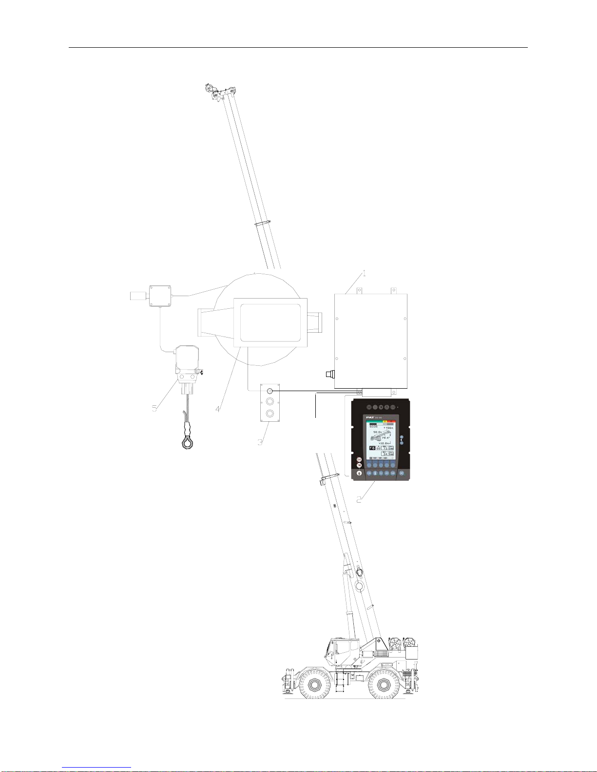
Fig. 1: Components of the LMI system PAT iFLEX5
1 Central-Micro-Processor Unit
2 Operating Console
3 Pressure Transducers
4 Length/Angle Sensor
5 Anti Two-Block Switch(es)
POWER
LOCKOUT
OTHER
PAT

Operator's Manual iFLEX5
© Hirschmann Rev. E 11/12/08 190147_E
4
3.1 SYSTEM FUNCTION
Upon switching on, the system starts with an
automatic test of the LMI system, of lamps
and audible alarm. During the test, the LC
display shows the initial logo.
If the system was turned off for more than
two hours, the setup configuration has to be
entered after the system test. (⇒chapter 4)
First, the operating mode is determined by
an interactive step-by-step interrogation of
the rigging states.
Next is the interactive input of the reeving.
Now the LC display shows in symbols all
inputs and awaits acknowledgment or
canceling.
Upon acknowledgment of the inputs the
system is ready for operation.

System Description
© Hirschmann Rev. E 11/12/08 190147_E
5
3.2 OPERATING CONSOLE
The console has 3 functions:
•inputs by the crane operator (operating mode, reeving)
•input of geometry limit values and signalization of exceeded limit values
•display of important data and information
The operator’s console is mounted in the crane’s cab in the operator’s field of vision. For a
better identification of displays and operating elements, they are continuously backlit during
operation.
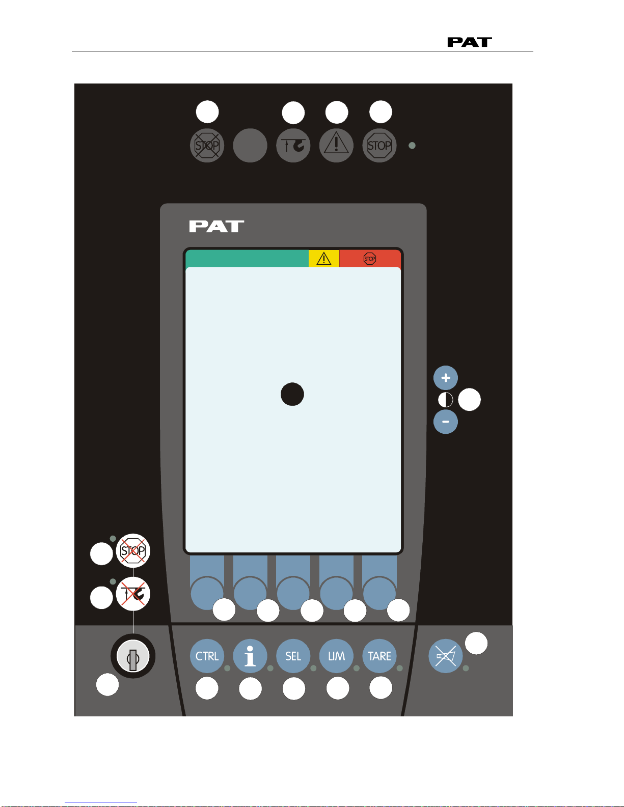
3.3 CONTROL IDENTIFICATION
This unit contains a display and different controls which are described as follows:
Legend to Fig 2:
1 LC Display Area 10 Button and Control Light "INFO"
2 Load Moment Limit Light 11 Button and Control Light "CONTROL"
3 Load Moment Prewarning Light 12 By-Pass Key Switch
4 Alarm Light “Anti-Two-Block” 13 Button and Control Light "By-Pass Anti-Two-Block"
5 Override Key Warning Light 14 Button and Control Light "By-Pass LMI shut-off
function"
6 Button “Alarm Stop” 15 Contrast Control
7 Button and Control Light “TARE” F1 Button "Function 1"
8 Button and Control Light “LIMITS” F2 Button "Function 2"
9 Button and Control Light “SELECT F3 Button "Function 3"
OPERATING MODE” F4 Button "Function 4"
F5 Button "Function 5"
Operator's Manual iFLEX5
© Hirschmann Rev. E 11/12/08 190147_E
6
Fig. 2a: Operating Console (vertical)
2
3
4
5
6
7
8
10
11
12
13
14
15
F1
F2F3
F4
F5
9
1

System Description
© Hirschmann Rev. E 11/12/08 190147_E
7
Fig. 2b: Operating Console (horizontal)
1 LC Display Area 10 Button and Control Light "INFO"
2 Load Moment Limit Light 11 Button and Control Light "CONTROL"
3 Load Moment Prewarning Light 12 By-Pass Key Switch
4 Alarm Light “Anti-Two-Block” 13 Button and Control Light "By-Pass Anti-Two-Block"
5 Override Key Warning Light 14 Button and Control Light "By-Pass LMI shut-off
function"
6 Button “Alarm Stop” 15 Contrast Control
7 Button and Control Light “TARE” F1 Button "Function 1"
8 Button and Control Light “LIMITS” F2 Button "Function 2"
9 Button and Control Light “SELECT F3 Button "Function 3"
OPERATING MODE” F4 Button "Function 4"
F5 Button "Function 5"
2
3
4
5
6
7
8
10
11
12 13 14
15
F1
F2
F3
F4
F5
9
1

Operator's Manual iFLEX5
© Hirschmann Rev. E 11/12/08 190147_E
8
LC-Display
The LC display visualizes graphical symbols, texts and numerical
values. Depending on the selected operating mode (setup, limit mode
or LMI representation), the corresponding information is indicated on
the display.
Please refer to the description of the different operating modes for the
signification of the individual elements.
Load Moment Limit Light
The red LOAD MOMENT LIMIT LIGHT (2) warns the operator that a
rated load condition has been reached. It lights up when the load on
the crane reaches the crane load capacity. The audible alarm also
sounds when this condition has been reached.
The following crane movements will be stopped concurrently:
− hoist up
− telescope out
− boom down
Load Moment Prewarning Light
The yellow LOAD MOMENT PRE-WARNING LIGHT (3) will light up
when the load on the crane reaches the defined prewarning area,
thus indicating that an overload condition is approaching.
This means for the operator to continue his crane operation with
extreme caution.
Alarm Light “Anti-2-Block”
The red “Anti Two-Block Alarm Light” (4) lights up when the anti-two-
block limit switch contacts open, indicating that a two-blocking
condition is approaching. At the same time the audible alarm will
sound.
The following crane movements will be stopped subsequently: hoist
up, telescope out, boom down.
Override Key Warning Light
The red OVERRIDE KEY WARNING LIGHT (5) flashes to indicate
that the cut-off function of the A2B / LMI system is deactivated.
Button and Control Light “Alarm Stop”
This ALARM STOP BUTTON (6) allows the audible alarm to be
silenced for approximately 15 seconds by pressing this button.
Reference ⇒“Audible Alarm” (12).

System Description
© Hirschmann Rev. E 11/12/08 190147_E
9
Button and Control Light “TARE”
The button “TARE” (7) is used to indicate the “Net load” on the LC
Display (1). Net load is the present load, less lifting tackle and hook
block. The Tare Button (7) has to be activated before lifting.
After pushing the “Tare Button” (7) the load display is set to zero
(taring) and the control light lights up. After lifting a load the display
shows the net load (pay load).
The net load display will change to the actual load display when the
boom radius is changed (either by angle or length).
Button "LIMITS"
Button to start the function "program limit values".
For the proceeding please refer to ⇒chapter 5.1.
Button "SELECT"
Button to start the function "set operating mode".
For the proceeding please refer to ⇒chapter 4.1.
The correct setting is of utmost importance for the proper function of the system and
the crane. Therefore only operators who are thoroughly familiar with use and
operation of the system shall set this button.
Button "INFO"
Button to start the function "information crane configuration"
Please refer to ⇒chapter 5.2.
Button "CONTROL"
Button to start additional functions.
Please refer to ⇒chapter 5.3.

Operator's Manual iFLEX5
© Hirschmann Rev. E 11/12/08 190147_E
10
Key Switch
The anti-two-block switch cut-off function is deactivated when
the KEY SWITCH (12) is turned to position "B" and the “By-pass
A2B” button (13) is pushed.
OR
The LMI cut-off function is deactivated when the KEY SWITCH
(12) is turned to position "B" and the “By-pass LMI” button (14) is
pushed.
KEY SWITCH (12) can be operated only by using the matching key.
Button "By-pass A2B"
This button can be operated only if key switch (12) is turned to
position B.
After pushing this button, the cut-off function of the anti-two-block
switch is deactivated.
The Override Key Warning Light (5) flashes to indicate that the cut-off
function is deactivated.
Since button (14) and (15) deactivate the cut-off function of the LMI system / the anti two-
block system, the following instructions must be obeyed:
•The by-pass function shall be used with discretion, as unwarranted use of it to override
the control lever lockout system can result in harm to the crane and danger to property
and persons.
•Never use the by-pass function to either overload or operate the crane in a non-
permissible range.
Button "By-pass LMI"
This button can be operated only if the key switch (12) is turned to
position B.
After pushing this button, the control lever lockout function of the LMI
is deactivated.
The Override Key Warning Light (5) flashes to indicate that the cut-off
function is deactivated.
Contrast Control
This function serves for the contrast adjustment of the LC display.
The last adjustment is stored and does not have to be repeated at
every system start.
During normal LMI operation the display contrast can be adjusted by
pressing the “+” or “-“ button.

Configuration Setup
© Hirschmann Rev. E 11/12/08 190147_E
11
4 CONFIGURATION SETUP
The LMI setup procedure allows the operator to input the crane configuration using interactive
displays. The operator must complete the setup procedure for the Load Moment Indicator
system if the system has been turned off for more than two hours or the crane operation
configuration has been changed.
4.1 LMI SETUP PROCEDURE
...starts: automatically, if the system was turned off for more than
two hours.
manually at each modification of the crane configuration
by pressing key (9) "SEL"
9
...is operated: by answering the different questions using functional keys
F1...F5 in accordance with the actual configuration of the
crane.
...is cancelled: any time by pressing again key (9) "SEL". The system,
however, is only ready for operation, if the procedure has
been completed and the inputs have been confirmed.
If the system is turned off, for example during short breaks (less than 2 hours), all adjustments
remain stored. When turning on again the system these adjustments can be acknowledged by
merely pressing one key (provided that the crane configuration has not been modified!).
During the programming procedure the Load Moment Prewarning Light (3) and the Load
Moment Limit Light (2) will light up and the aggravating crane movements will be interrupted.
Note: If a configuration is selected which is not available, the display will indicate error code
E04. In this case, the procedure has to be repeated with valid values!
The correct setting is of utmost importance for the proper functioning of the system
and the crane. Therefore, only operators who are thoroughly familiar with the crane
and the operation of the system should execute the setting of the system according
the operating configuration of the crane.

Operator's Manual iFLEX5
© Hirschmann Rev. E 11/12/08 190147_E
12
The LMI programming procedure consists of the following steps:
•setting the boom configuration
•setting the counterweight configuration (where applicable)
•setting the hoist configuration
•setting the outrigger configuration
•setting the reevings
•confirmation of the programming procedure
For easy operation, the computer guides the operator through the procedure step by step
(interactive operation.)
Definition of the Displayed Symbols:
The following illustrations define the symbols appearing on the display during the setup
procedure. Not all symbols will be shown, depending on the crane type and the answers to the
questions.
•Select interactive configuration setup / special mode setup
interactive configuration setup
special mode setup
Note: Refer to manufacturer load
chart for special LMI operating code
•(if selected special mode setup only)
increase selected numeral
decrease selected numeral
select next numeral
confirm selected operating code
•Setting the boom configuration
main boom / aux. boom nose operation
operation with boom extensions, includes luffing jib operation
rigging mode operation*
*
for cranes with rigging mode for outrigger box installation only
or
main boom
operation with boom extensions

Configuration Setup
© Hirschmann Rev. E 11/12/08 190147_E
13
•Setting the luffer configuration
extension retracted
extension extended
main
boom aux.
boom
nose
A-
frame
boom
ext.
fixed
ext. fixed,
offsettable
extension
tele-offsettable
extension fixed jib Luffing jib
For detailed symbol explanation of extensions, please refer to Appendix A in this manual.
•Setting the counterweight configuration
If your crane is equipped with counterweight options, please
refer to Appendix B in this manual for detailed symbol
explanation of counterweight.
•Setting the hoist configuration
Front Hoist
Rear Hoist
•Setting the outrigger configuration (If no outrigger configuration is skipped,
configuration can only be used with 100% outrigger position).
on rubber
outrigger position 0%
outrigger position 50%
outrigger position 100%
Operator's Manual iFLEX5
© Hirschmann Rev. E 11/12/08 190147_E
14
•(if selected on rubber mode only)
static
pick & carry
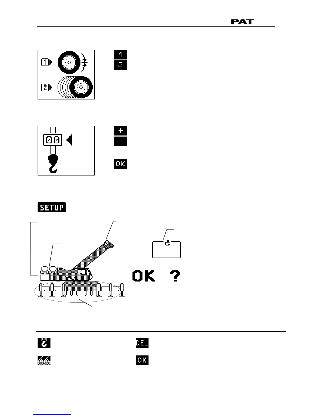
•Setting the reeving (parts of line)
increase reeving
decrease reeving
confirm reeving
•Confirmation of the programming procedure
At the end of the procedure all selections are shown once again in symbolic forms. If selections have
been made, the corresponding symbols are filled black.
quick setting the reeving
(⇒chapter 4.3)
quick hoist line selection
(⇒chapter 4.2)
cancel procedure
confirm inputs
counterweight
configuration
(optional)
hoist
selection
boom
configuration
outrigger
configuration
reeving
(parts of line)
Other manuals for PAT IFLEX5
1
Table of contents
Other Hirschmann Music Mixer manuals


