Hisun 450ATV-2 User manual

450ATV-2 Maintenance Manual

eneral Information
1 Description
1.1 Identification code
1.1.1. Frame No.
1.1.2. Engine No.
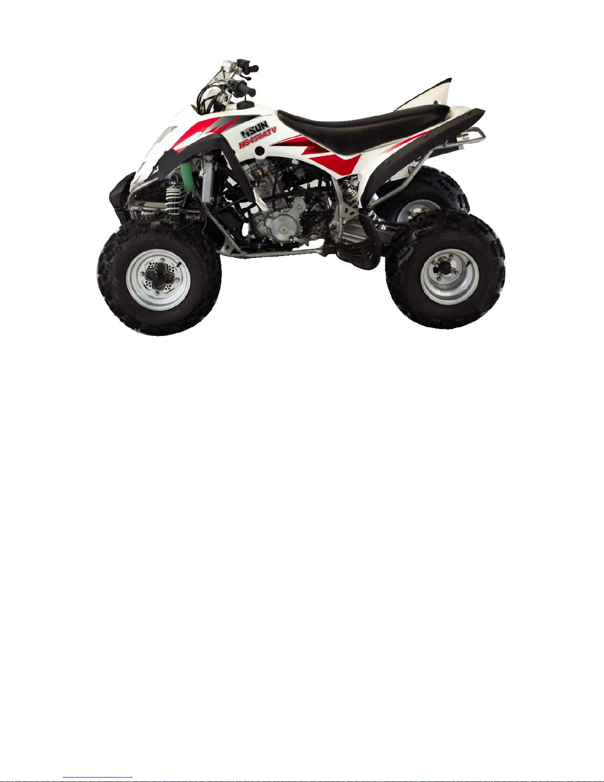
1.2 Special tools, instruments and meters
1.3 Periodic maintenance chart
Chassis
4.1 Steering operation system
4.2 Brake system
4.3 Wheels and tires
4.4 Transmission system
4.5 Reverse mechanism
4.6 Suspension
4.7 Cooling system of engine
4.8 Parking mechanism
4.9 Oil circulation System
4.10 Speed sensor
Electrical system
5.1 Ignition system
5.2 Magneto and charging system
5.3 Battery
5.4 Lighting system
5.5 Meter and signal system
5.6 Starting system
Appendix
6.1 Specification
6.2 Requirements for torque of fastener
6.3 Electrical circuits
General Information
1 Description

1.1 Identification code
1.1.1. Frame No.
The frame No. is engraved in the right bottom of the supporting frame. See Figure
1-1

Figure 1-1
1.1.2. Engine No.
The engine No. is engraved in the right side of the engine. See figure 1-2
Figure 1-2
1.2 Special tools, instruments and meters
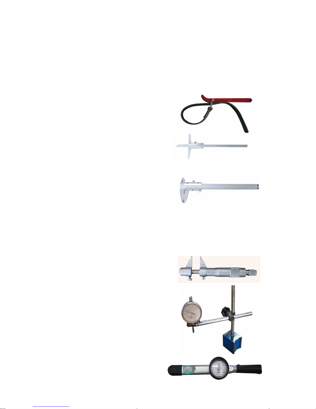
1.2.1 Oil filter detacher
To fasten and detach the oil filter
1.2.2 Height gauge
To gauge the height of various components
1.2.3 Vernier
To measure the length of various components
1.2.4 Outside micrometer
To accurately measure external
diameter of a column
1.2.5 Inside micrometer
To accurately measure internal
diameter of a hole
1.2.6 Dial indicator
To accurately measure a small
distance
1.2.7 Torque Spanner
To measure torque force
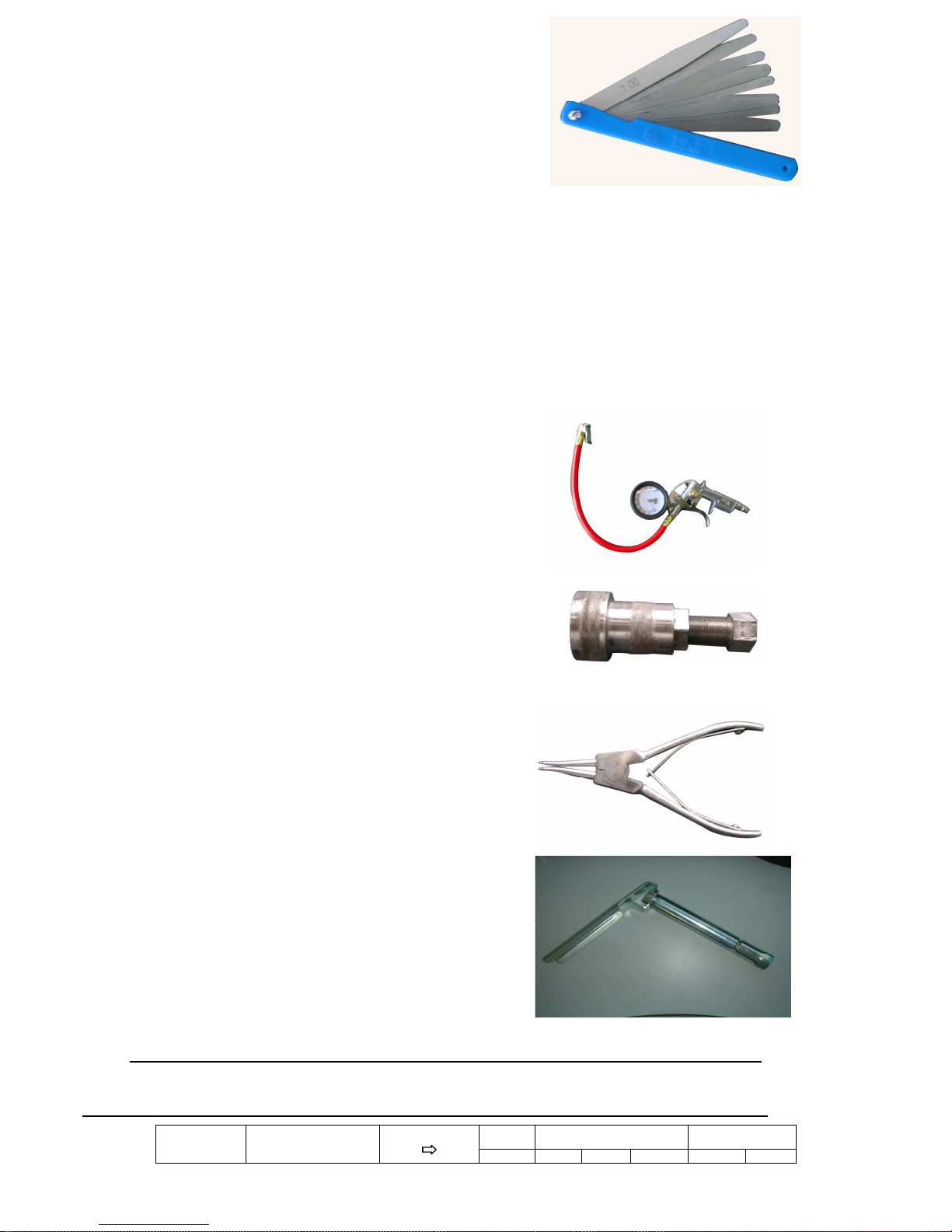
1.2.8 Feeler gauge
To measure gap-width
1.2.9 Multimeter
To check electrical circuits and parts
1.2.10 Barometer
To measure pressure of the tyre
1.2.11 Magneto drawing device
To detach the magneto
1.2.12 Snap ring clamp
To install and detach snap rings
1.2.13:
Spark tester of spark plug
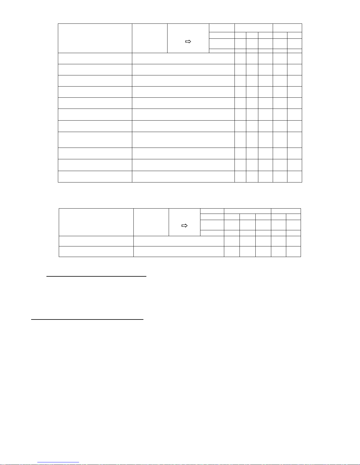
1.3 Periodic maintenance chart for the emission control system
NOTE:
●For ATVs not equipped with an odometer or an hour meter, follow the month maintenance intervals.
●For ATVs equipped with an odometer or an hour meter, follow the km (mi) or hours maintenance intervals. However, keep
in mind that if the ATV isn’t used for a long period of time, the month maintenance intervals should be followed.
INITIAL EVERY
ITEM ROUTINE Whichever
Comes first
Month 1 3 6 6 12
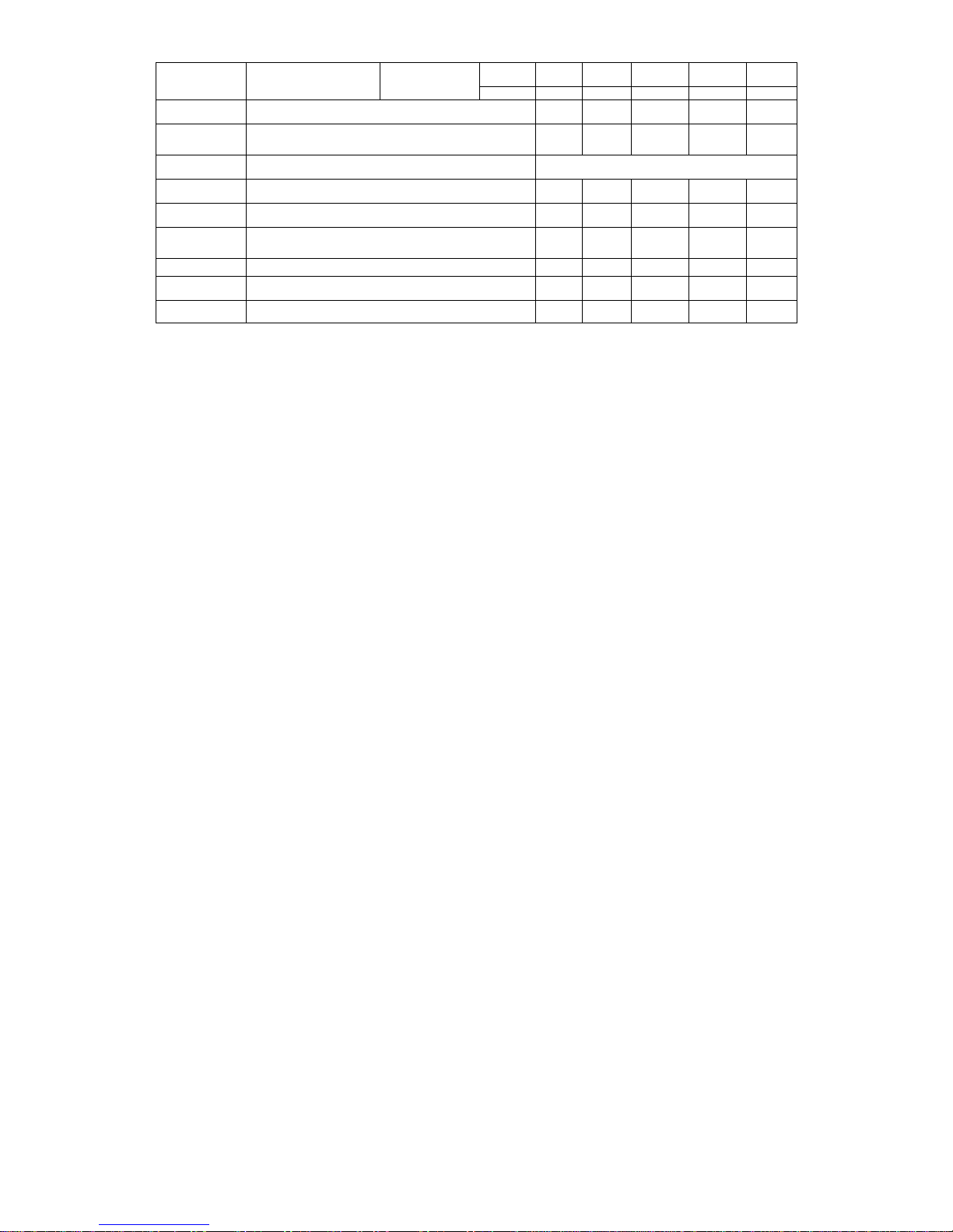
Km
(Mi) 320
(200) 1,200
(750) 2,400
(1,500) 2,400
(1,500) 4,800
(3,000)
Hours 20 75 150 150 300
Valves★Check valve clearance.
Adjust if necessary. ○○○○
Spark plug Check condition.
Adjust gap and clean.
Replace if necessary. ○○○○○
Air filter element
Clean.
Replace if necessary. Every 20-40 hours
(More often in wet or dusty areas.)
Carburetor★Check starter (choke) operation.
Adjust engine idling speed. ○○○○
Crankcase
breather system★
Check breather hose for cracks or damage.
Replace if necessary. ○○○
Exhaust system★
Check for leakage.
Tighten if necessary.
Replace gasket(s) if necessary. ○○○
Spark arrester Clean. ○○○
Fuel line★Check fuel hose for cracks or damage.
Replace if necessary. ○○○
Engine oil Replace (Warm engine before draining.) ○○○○
INITIAL EVERY
Month 1 3 6 6 12
Km
(Mi) 320
(200)
1,200
(750)
2,400
(1,500)
2,400
(1,500)
4,800
(3,000)
ITEM ROUTINE Whichever
Comes first
Hours 20
75
150 150 300
Engine oil filter element Clean.
Replace if necessary. ○
○○
Engine oil strainer Clean. ○
○○
Drive chain Check and adjust slack/alignment/clean/lube. ○
○○○○
Brakes★Check operation/fluid leakage/See NOTE.
Correct if necessary. ○
○○○○
Clutch★Check operation.
Adjust if necessary. ○
○○○
Wheels★Check balance/damage/run out.
Replace if necessary. ○
○○○
Wheels bearings★Check bearing assemblies for looseness/damage.
Replace if damaged. ○
○○○
Steering system★
Check operation.
Repair if damaged.
Check toe-in.
Adjust if necessary.
○
○○○○
Front and pan fork★Check operation.
Correct if necessary. ○○
Upper and lower arm pivot and steering shaft
★Lubricate every 6 months with lithium-soap-based
grease. ○○○
Rear arm pivot★Lubricate every 6 months with lithium-soap-based
grease. ○○○
INITIAL EVERY
Month 1 3 6 6 12
Km
(Mi) 320
(200)
1,200
(750)
2,400
(1,500)
2,400
(1,500)
4,800
(3,000)
ITEM ROUTINE Whichever
Comes first
Hours 20 75 150 150 300
Fittings and fastener★Check all chassis fittings and fasteners.
Correct if necessary. ○○○○○
Lights and a witches★Check operation.
Adjust headlight beams. ○○○○○
★Science these lets require special tools, data and technical skills, Have the dealer perform the service.
NOTE:
Recommended brake fluid:DOT4
Brake fluid replacement:
When disassembling the master cylinders or calipers, replace the brake fluid.
Normally check the brake fluid level and add fluid as required.
On the inner parts of the master cylinders and scalpers, replace the oil seals every two years.
Replace the brake hoses every four years, or if cracked of damaged.
Chassis

10
4.1
Steering system
Structure of Steering Vertical Column
Components of Steering Bar
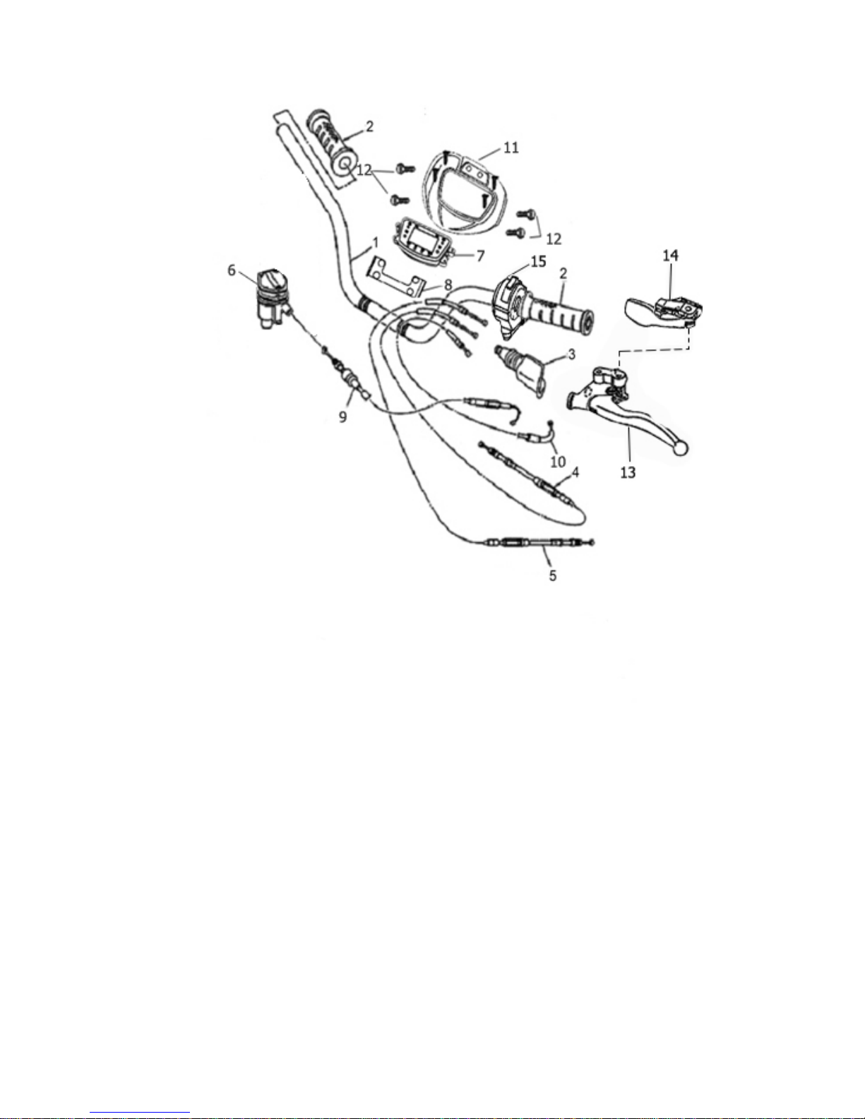
11
4.1.1
Disassembly, inspection and assembly of Steering
System
12
4.1.1.1 Disassembly of Steering Vertical Column (Steering Bar
included)
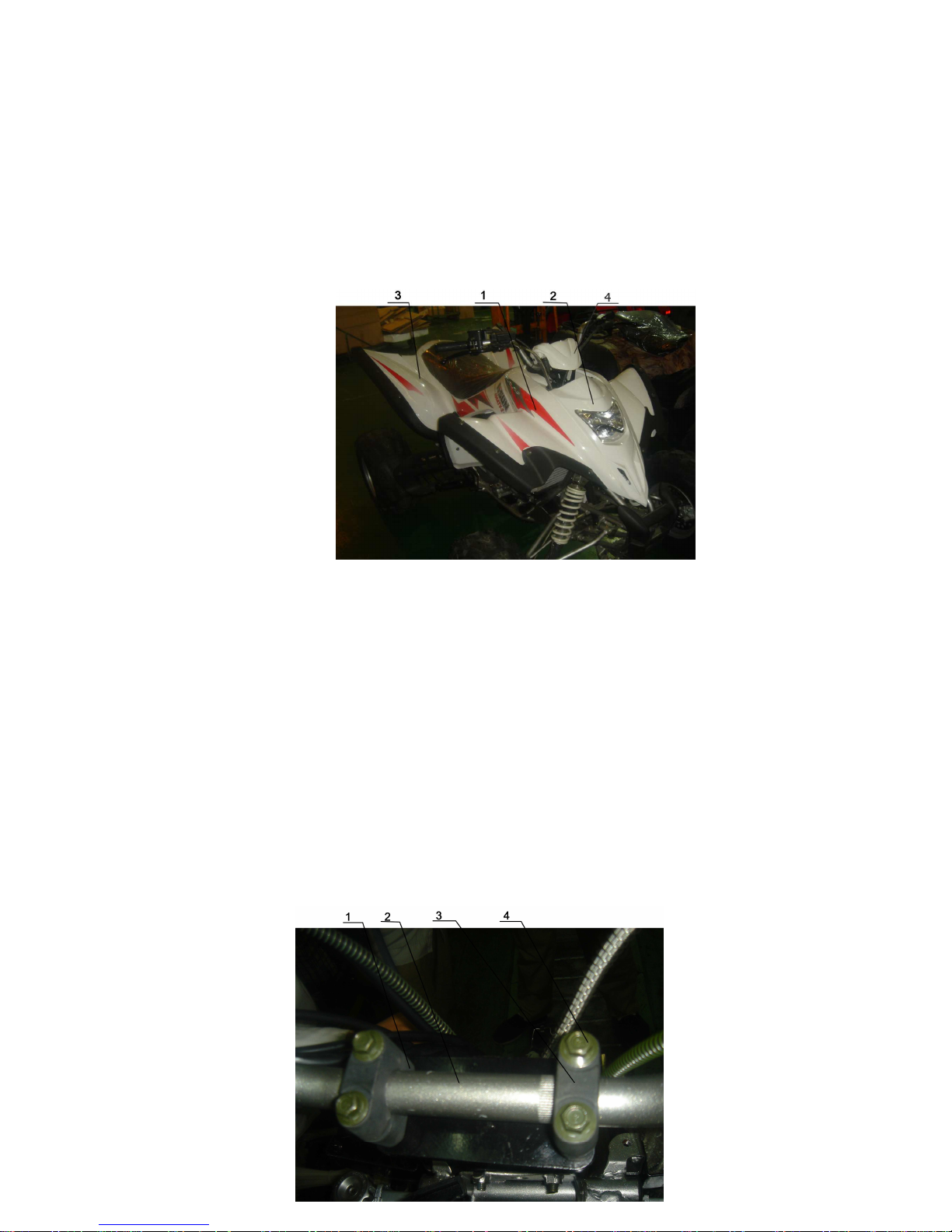
1、Remove the Front Faceplate and Meter Cover (Figure
4-1-1)
Figure 4-1-1
1、Front Mud Shield
2、Front Faceplate
3、Rear Mud Shield
4、Meter cover
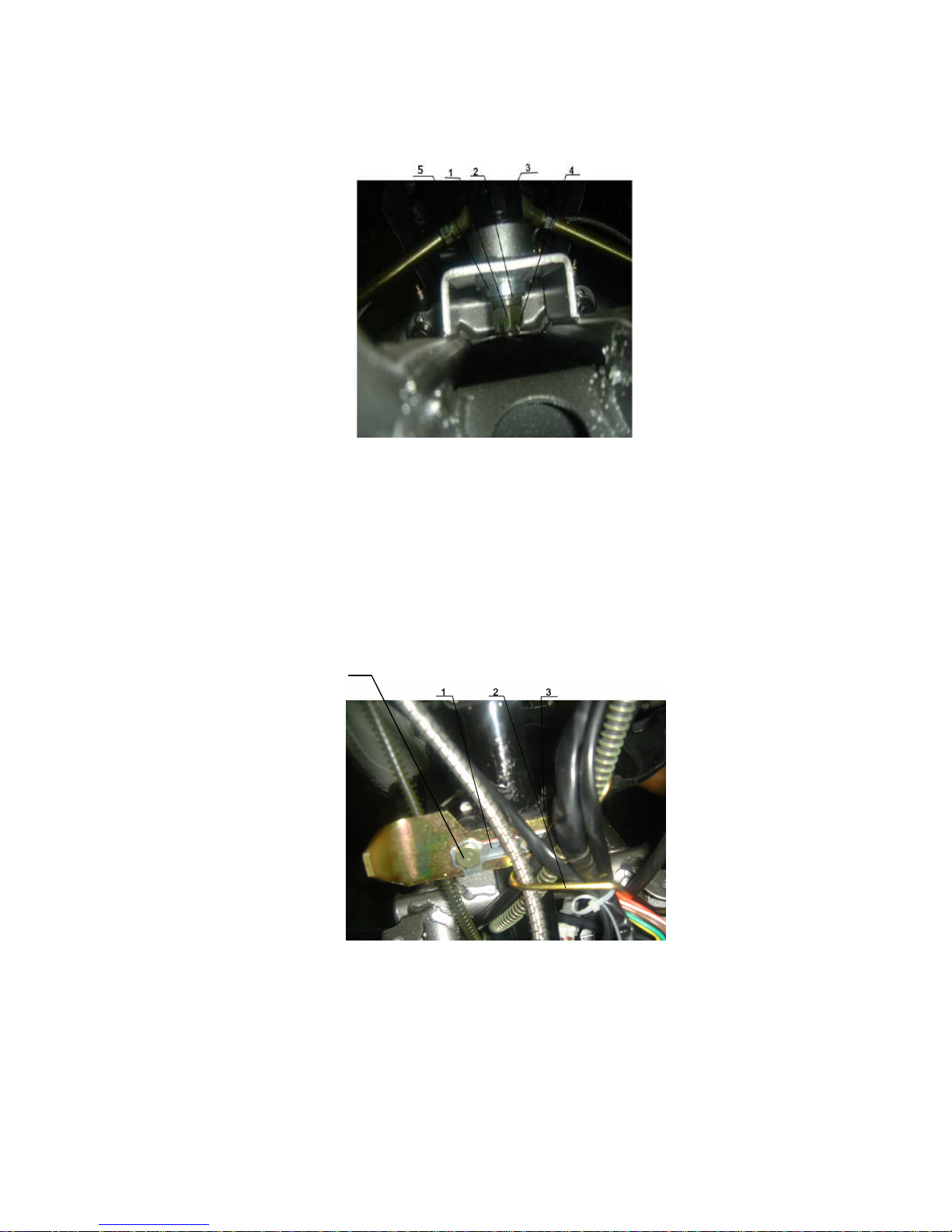
2、Release the hexagon flange bolt M8×30(4pcs) and
remove the steering bar clip

13
Steering Bar Holder
1、Steering Bar
2、Steering Bar Clip
3、Hexagon Flange Bolt M8×30
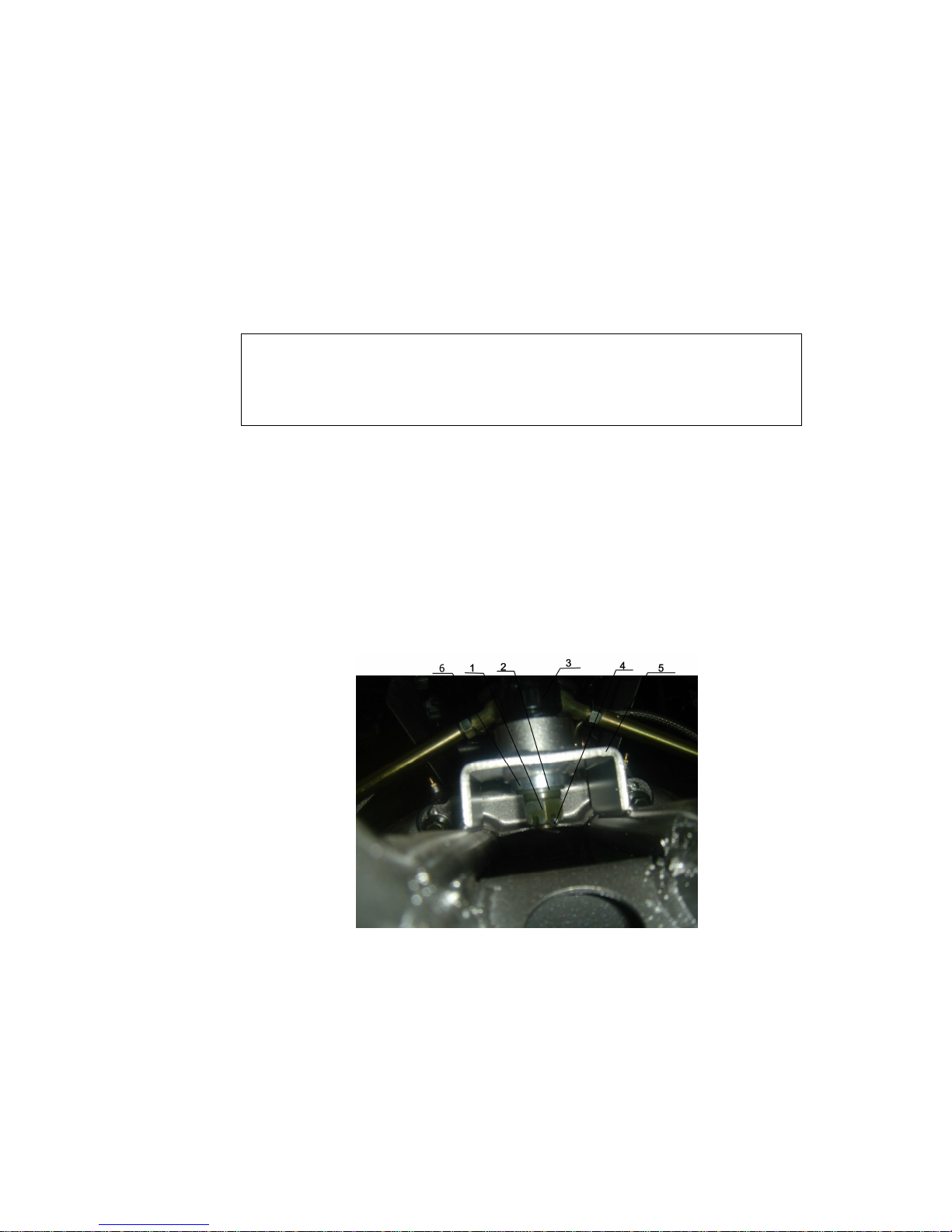
3、 Remove Front Brake Lever and unplug all cables and
connecting wires. (Figure 4-1-3)
Figure 4-1-3
1、 Throttle Cable 2、Connecting Wire
3、 Clutch Cable 4、Brake fuel pipe
4、 Front Brake Handlebar 6、Choke Cable
7、Parking Cable
4、Remove the cotter pin, M14 open-groove nut, cushion
and lower collar sheath at the bottom of the
14
Steering Vertical Column. (Figure 4-1-4)
Figure 4-1-4
1、Hexagon open-groove nut 2、4 cushionф14×ф32×4
3、Steering vertical column 4、 cotter pin 3.2×32
5、Lower collar sheath
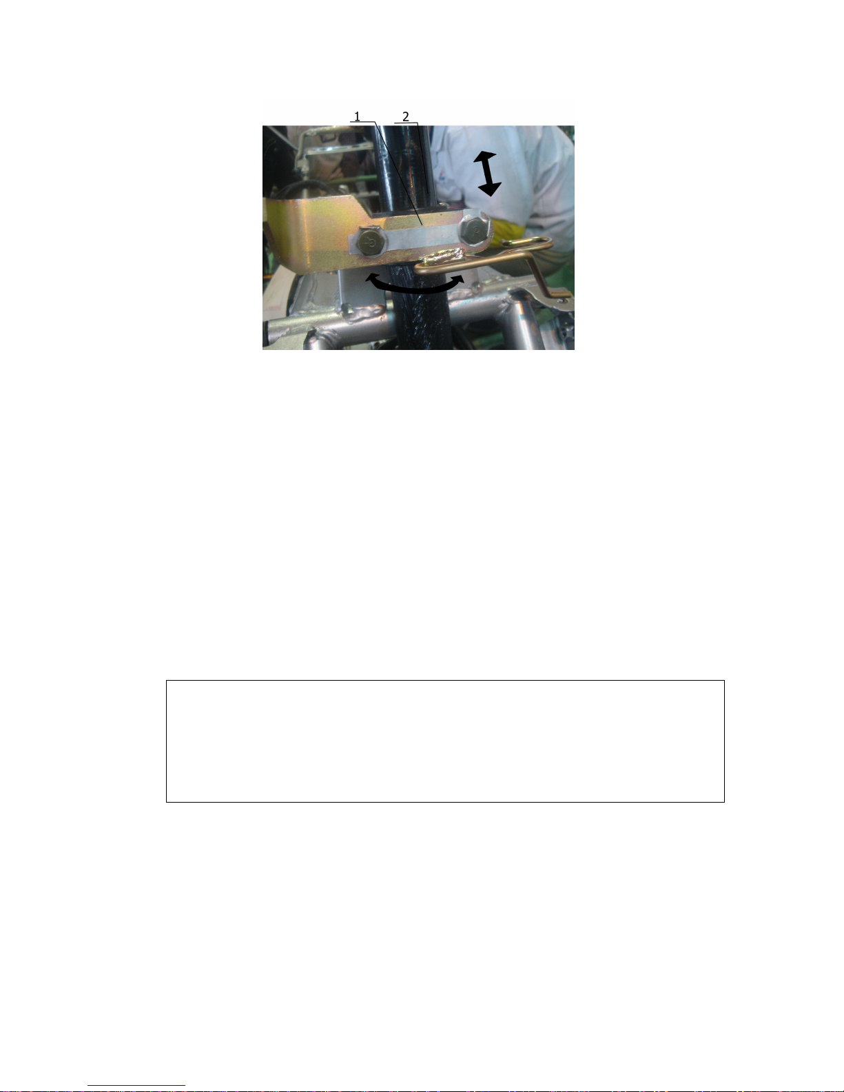
5、
Release M8*32 Bolt (2pcs) and remove the supporting brackets of the
steering vertical column
4
6、Rotate the tension rod to detach it from the balance
(Figure 4-1-6)

15
Figure 4-1-6
1、Tension rod
7、Pull out the components of the steering vertical
column from the bottom seat.
Steering Vertical Column 2、Bottom Seat
4.1.1.2 Inspection of steering vertical column components:
1、Check whether the hexagon open-groove nut between the
inner ball pin and tension rod is tightened

16
4-1-8
1、Tension rod
2、cotter pin 3.2*32
3、Turning shaft arm 4 、 Hexagon
open-groove nut
5、Ball pin
In case of loosen or worn out, tighten it with proper tools
or replace with identical nuts.
Torque of the open-groove nut: 32-36N.m
2、Check whether the inner and outter ball pin of the tension
rod is loosen or got stuck.
17
1. Tension rod
In occasion of above defects, further inspection of the
exact causation must be carried out and replace with new
ball pin components.
Caution: Continuous use of defective ball pin might
cause severe injury or death.
Additionally, check whether the tension rod is bended,
cracked or rusted.
In occasion of above problems, please have the tension
rod replaced.

18
。
3、Check whether the hexagon open-groove nut and cottor pin
are intact. (No crack or flaw is allowed)
Figure 4-1-10
1.M14 Open-groove nut 2、Cushion
3、Steering vertical column 4、Cotter pin
3.2*32
5、collar sheath
Those two components are crucial and should be
replaced whenever there is a potential problem.
4、Check whether the supporing bracket is firmly fixed to
the steering vertical column.
Caution: tension rod should not be repaired by
welding
19
1. inner and outter supporting
bracket 2、steering vertical column
Inspection method:
Assemble the steering vertical column to the main frame
with supporting bracket and M8 bolts etc. and rotate the
steering bar to ensure the column is not stuck or swinging.
In occasion of above problems, the supporting bracket
must be replaced.
Rotating Torque of the steering vertical column:
3-5N.m
5、Check whether the bearing in the bottom seat is rotating
smoothly and oil seals on both ends are not damaged.
Should there occurs any problem, the bearing or oil seal
must be replaced immediately.
4.1.1.3 Assembly of steering vertical column
20
1、Plug the steering vertical column into the bottom seat
and fix it with M14 open-groove nut (1pcs),ф14×ф36
×4 cushion (1pcs), collar sheath (1pcs) and 3.2*32
cotter pin (1pcs).
Fastening Torque of M14 open-
groove nut:
80-85N.m
Caution: before inserting the steering
vertical column into the bottom seat, both upper and
lower oil seals must be greased with lithium
lubrication.
4-1-12
1、Hexagon open-groove nut M14×1.5
2、 Cushion
3、 Steering vertical column
4、Cotter pin 3.2×32
5、 Steering bottom seat
6、Lower collar sheath
Table of contents
Other Hisun Motorcycle manuals


