Hisun HS200UTV User manual

Published by Chongqing
Huansong Industries
(Group) Co., Ltd and
Hisun Motors Corp USA.
Chongqing Huansong
Industries (Group) Co., Ltd
and Hisun Motors Corp USA
holds the copy right.
No publishing and reprinting
without permission.
READ THIS
MANUAL CAREFULLY
For questions regarding this
UTV, please contact HISUN at:
(972)446-0760
hisunmotors.com
Rev. 06031601
No one under the age of 12
should operate this vehicle.
Provincial / Municipal
governments have dierent
regulations pertaining to
owning and operating an
o-road vehicle; learn the
regulations in your area.
STRIKE 250
SERVICE MANUAL
TM
GRAB SOME SUN

FOREWORD
Brief introduction to maintenance handbook of
HS250UTV/HS200UTV
The handbook is edited by Technical Center of Chongqing Huansong Science And
Technology Industrial Co.,Ltd, and is supplied to dealers and technicians as document of
technique.Mainly, the handbook gives methods to check, maintain and repair utility terrain
vehicles (UTV), and supplies some relevant technique and performance data. Some
techniques and method inside may be used to check, maintain and repair other models of
UTV, although it is mainly for HS250UTV/HS200UTV.
Please read the handbook through and fully understand it; otherwise, any improper
repairing and amounting would bring you problems, and accident may occur in your use.
Proper use and maintenance can guarantee UTV being driven safely, reduce its
malfunction, and help the vehicle remain its best performance.
The standards, performances and specifications mentioned in interpretation are
based on the sample in design, and they are subject to changes according to the
product’s improvement without prior notice.
First version , October, 2014
Published by Chongqing Huansong Science And Technology Industrial Co.,Ltd
Chongqing Huansong Science And Technology Industrial Co.,Ltd holds the copy right.
No publishing and reprinting without permission.

- 1 -
CONTENT
CHAPTER 1
GENERAL INFORMATION
GENERAL INFORMATION……………………………………………………………………1
WATNINGS, CAUTIONS AND NOTES……………………………………………………1
DESCRIPTION……………………………………………………………………………………2
IDENTIFICATION CODE……………………………………………………………………… 3
Frame No. ………………………………………………………………………………… 3
Engine No. ………………………………………………………………………………… 3
SAFETY ………………………………………………………………………………………… 4
Handing gasoline safely…………………………………………………………………… 4
Cleaning parts……………………………………………………………………………… 5
Warning labels……………………………………………………………………………… 5
SERIAL NUMBERS…………………………………………………………………………… 6
FASTENERS…………………………………………………………………………………… 6
Torque specifications ……………………………………………………………………… 6
Self-locking fasteners……………………………………………………………………… 6
Washers…………………………………………………………………………………… 6
Cotter pins…………………………………………………………………………………… 7
Snap rings and E-clips …………………………………………………………………… 7
SHOP SUPPLIES……………………………………………………………………………… 8
Lubricants and Fluids……………………………………………………………………… 8
Engine oils…………………………………………………………………………………… 8
Greases……………………………………………………………………………………… 8
Brake fluid…………………………………………………………………………………… 9
Coolant……………………………………………………………………………………… 9
Cleaners, Degreasers and solvents …………………………………………………… 9
Gasket sealant…………………………………………………………………………… 9
Gasket remover ………………………………………………………………………… 10
Thread locking compound……………………………………………………………… 10
BASIC TOOLS ………………………………………………………………………………… 10
Screwdrivers……………………………………………………………………………… 11

1
- 1 -
CONTENT
CHAPTER 1
GENERAL INFORMATION
GENERAL INFORMATION……………………………………………………………………1
WATNINGS, CAUTIONS AND NOTES……………………………………………………1
DESCRIPTION……………………………………………………………………………………2
IDENTIFICATION CODE……………………………………………………………………… 3
Frame No. ………………………………………………………………………………… 3
Engine No. ………………………………………………………………………………… 3
SAFETY ………………………………………………………………………………………… 4
Handing gasoline safely…………………………………………………………………… 4
Cleaning parts……………………………………………………………………………… 5
Warning labels……………………………………………………………………………… 5
SERIAL NUMBERS…………………………………………………………………………… 6
FASTENERS…………………………………………………………………………………… 6
Torque specifications ……………………………………………………………………… 6
Self-locking fasteners……………………………………………………………………… 6
Washers…………………………………………………………………………………… 6
Cotter pins…………………………………………………………………………………… 7
Snap rings and E-clips …………………………………………………………………… 7
SHOP SUPPLIES……………………………………………………………………………… 8
Lubricants and Fluids……………………………………………………………………… 8
Engine oils…………………………………………………………………………………… 8
Greases……………………………………………………………………………………… 8
Brake fluid…………………………………………………………………………………… 9
Coolant……………………………………………………………………………………… 9
Cleaners, Degreasers and solvents …………………………………………………… 9
Gasket sealant…………………………………………………………………………… 9
Gasket remover ………………………………………………………………………… 10
Thread locking compound……………………………………………………………… 10
BASIC TOOLS ………………………………………………………………………………… 10
Screwdrivers……………………………………………………………………………… 11

2
- 2 -
Wrenches ………………………………………………………………………………… 11
Adjustable wrenches …………………………………………………………………… 12
Socket wrenches, ratchets and handles ……………………………………………… 12
Impact drivers …………………………………………………………………………… 13
Allen wrenches…………………………………………………………………………… 13
Torque wrenches………………………………………………………………………… 13
Torque adapters ………………………………………………………………………… 14
Pliers……………………………………………………………………………………… 15
Snap ring pliers…………………………………………………………………………… 15
Hammers ………………………………………………………………………………… 16
Ignition grounding tool…………………………………………………………………… 16
PRECISION MEASURING TOOLS ………………………………………………………… 16
Feeler gauge ……………………………………………………………………………… 16
Calipers…………………………………………………………………………………… 17
Micrometers……………………………………………………………………………… 17
Adjustment ……………………………………………………………………………… 18
Care ……………………………………………………………………………………… 19
Metric micrometer………………………………………………………………………… 19
Standard inch micrometer……………………………………………………………… 20
Telescoping and small bore gauges…………………………………………………… 21
Dial Indicator……………………………………………………………………………… 21
Compression gauge……………………………………………………………………… 22
Multimeter………………………………………………………………………………… 22
Cltp-on ammeter………………………………………………………………………… 22
Magneto puller………………………………………………………………………………23
ELECTRICAL SYSTEM FUNDAMENTALS……………………………………………… 23
Voltage …………………………………………………………………………………… 23
Resistance………………………………………………………………………………… 23
Amperage………………………………………………………………………………… 23
BASIC SERVICE METHODS……………………………………………………………… 24
Removing frozen fasteners……………………………………………………………… 25
Removing broken fasteners …………………………………………………………… 25
Repairing damaged threads …………………………………………………………… 26
Stud Removal/Installation ……………………………………………………………… 26
- 3 -
Removing hoses ………………………………………………………………………… 27
Bearings…………………………………………………………………………………… 27
Removal…………………………………………………………………………………… 27
Installation………………………………………………………………………………… 28
Interference fit …………………………………………………………………………… 28
Seal replacement………………………………………………………………………… 30
STORAGE……………………………………………………………………………………… 30
Storage area selection…………………………………………………………………… 30
Preparing the motorcycle for storage …………………………………………………… 30
Returning the UTV to service…………………………………………………… 31
TROVBLESHOOTING……………………………………………………………………… 31
ENGINE PRINCIPLES AND OPERATING REQUIREMENTS………………………… 32
STARTING THE ENGINE ………………………………………………………………… 32
Engine is cold …………………………………………………………………………… 33
Engine is warm…………………………………………………………………………… 33
Flooded engine……………………………………………………………………………33
ENGINE WILL NOT START ……………………………………………………………… 34
Identifying the problem ………………………………………………………………… 34
Spark test………………………………………………………………………………… 35
The starter cannot work repeatedly or can only work slowly………………… 36
POOR ENGINE PERFORMANCE………………………………………………………… 36
The engine starts slowly or difficultly…………………………………………… 36
Engine backfires, cuts out or misfires during acceleration…………………………… 36
The engine is not idling or cannot idle stably…………………………………………… 37
Poor fuel mileage………………………………………………………………………… 37
Engine will not idle or idles roughly …………………………………………………… 37
Low engine power ………………………………………………………………………… 38
Poor idle or low speed performance…………………………………………………… 39
Poor high speed performance ………………………………………………………… 39
FUEL SYSTEM……………………………………………………………………………… 40
Rich mixture……………………………………………………………………………… 40
Lean mixture……………………………………………………………………………… 40
ENGINE………………………………………………………………………………………… 40
Engine smoke……………………………………………………………………………… 40

3
- 3 -
Removing hoses ………………………………………………………………………… 27
Bearings…………………………………………………………………………………… 27
Removal…………………………………………………………………………………… 27
Installation………………………………………………………………………………… 28
Interference fit …………………………………………………………………………… 28
Seal replacement………………………………………………………………………… 30
STORAGE……………………………………………………………………………………… 30
Storage area selection…………………………………………………………………… 30
Preparing the motorcycle for storage …………………………………………………… 30
Returning the UTV to service…………………………………………………… 31
TROVBLESHOOTING……………………………………………………………………… 31
ENGINE PRINCIPLES AND OPERATING REQUIREMENTS………………………… 32
STARTING THE ENGINE ………………………………………………………………… 32
Engine is cold …………………………………………………………………………… 33
Engine is warm…………………………………………………………………………… 33
Flooded engine……………………………………………………………………………33
ENGINE WILL NOT START ……………………………………………………………… 34
Identifying the problem ………………………………………………………………… 34
Spark test………………………………………………………………………………… 35
The starter cannot work repeatedly or can only work slowly………………… 36
POOR ENGINE PERFORMANCE………………………………………………………… 36
The engine starts slowly or difficultly…………………………………………… 36
Engine backfires, cuts out or misfires during acceleration…………………………… 36
The engine is not idling or cannot idle stably…………………………………………… 37
Poor fuel mileage………………………………………………………………………… 37
Engine will not idle or idles roughly …………………………………………………… 37
Low engine power ………………………………………………………………………… 38
Poor idle or low speed performance…………………………………………………… 39
Poor high speed performance ………………………………………………………… 39
FUEL SYSTEM……………………………………………………………………………… 40
Rich mixture……………………………………………………………………………… 40
Lean mixture……………………………………………………………………………… 40
ENGINE………………………………………………………………………………………… 40
Engine smoke……………………………………………………………………………… 40

4
- 4 -
Black smoke ……………………………………………………………………………… 40
Blue smoke………………………………………………………………………………… 41
White smoke or steam…………………………………………………………………… 41
Low engine compression ………………………………………………………………… 41
High engine compression ……………………………………………………………… 41
Engine overheating (cooling system) ………………………………………………… 42
Engine overheating (engine)…………………………………………………………… 42
The ignition advance angle is too large………………………………………………… 42
Detonation………………………………………………………………………………… 42
Power loss ……………………………………………………………………………… 43
engine noises……………………………………………………………………………… 43
ENGLNE LUBRICATION…………………………………………………………………… 44
HIGH OIL CONSUMPTION OR EXCESSIVE……………………………………………… 44
Exhaust smoke…………………………………………………………………………… 44
Low oil pressure ………………………………………………………………………… 44
High oil pressure ………………………………………………………………………… 44
No oil pressure…………………………………………………………………………… 44
Oil level too low…………………………………………………………………………… 44
Oil contamination………………………………………………………………………… 45
CYLINDER LEAK DOWN TEST…………………………………………………………… 45
ELECTRICAL TESTING…………………………………………………………………… 47
Preliminary checks and precautions …………………………………………………… 47
Intermittent problems…………………………………………………………………… 48
Electrical component replacement ……………………………………………………… 49
Test equipment …………………………………………………………………………… 49
Ammeter …………………………………………………………………………………… 49
Self-powered test light …………………………………………………………………… 49
Ohmmeter ………………………………………………………………………………… 50
Jumper wire……………………………………………………………………………… 50
TEST PROCEDURES………………………………………………………………………… 51
Voltage test……………………………………………………………………………… 51
Voltage drop test………………………………………………………………………… 51
Peak voltage test………………………………………………………………………… 52
Continuity test……………………………………………………………………………… 52
- 5 -
Testing for a short with a self-powered test light or ohmmeter……………………… 52
Testing for a short with a test light or voltmeter………………………………………… 53
BRAKE SYSTEM……………………………………………………………………………… 53
Soft or spongy brake lever or pedal…………………………………………………… 53
Brake drag………………………………………………………………………………… 54
Hard brake lever or pedal operation…………………………………………………… 55
Brake Grabs……………………………………………………………………………… 55
Brake squeal or chatter ………………………………………………………………… 55
Leaking brake caliper …………………………………………………………………… 55
Leaking master cylinder………………………………………………………………… 56
CHAPTER 2
SPECIFICATIONS
HOW TO USE CONVERSION TABLE OF UNIT…………………………………………… 57
How to use conversion table…………………………………………………………… 57
Definition of unit ………………………………………………………………………… 57
GEBERAR SPECIFICATIONS ……………………………………………………………… 58
ENGINE SPECIFICATIONS ………………………………………………………………… 61
CHASSIS SPECIFICATIONS………………………………………………………………… 67
ELECTRICAL SPECIFICATIONS…………………………………………………………… 69
TIGHTENING TORQUES …………………………………………………………………… 71
Engine tightening torques………………………………………………………………… 71
Chassis tightening torques ……………………………………………………………… 74
GENERAL TIGHTENING TORQUE SPECIFICATIONS ………………………………… 76
LUBRICATION PIONTS AND LUBRICANT TYPES……………………………………… 77
Engine……………………………………………………………………………………… 77
Chassis……………………………………………………………………………………… 78
HYDROGRAPHIC CHART…………………………………………………………………… 79
LUBRICATION OIL WAY…………………………………………………………………… 80

5
- 5 -
Testing for a short with a self-powered test light or ohmmeter……………………… 52
Testing for a short with a test light or voltmeter………………………………………… 53
BRAKE SYSTEM……………………………………………………………………………… 53
Soft or spongy brake lever or pedal…………………………………………………… 53
Brake drag………………………………………………………………………………… 54
Hard brake lever or pedal operation…………………………………………………… 55
Brake Grabs……………………………………………………………………………… 55
Brake squeal or chatter ………………………………………………………………… 55
Leaking brake caliper …………………………………………………………………… 55
Leaking master cylinder………………………………………………………………… 56
CHAPTER 2
SPECIFICATIONS
HOW TO USE CONVERSION TABLE OF UNIT…………………………………………… 57
How to use conversion table…………………………………………………………… 57
Definition of unit ………………………………………………………………………… 57
GEBERAR SPECIFICATIONS ……………………………………………………………… 58
ENGINE SPECIFICATIONS ………………………………………………………………… 61
CHASSIS SPECIFICATIONS………………………………………………………………… 67
ELECTRICAL SPECIFICATIONS…………………………………………………………… 69
TIGHTENING TORQUES …………………………………………………………………… 71
Engine tightening torques………………………………………………………………… 71
Chassis tightening torques ……………………………………………………………… 74
GENERAL TIGHTENING TORQUE SPECIFICATIONS ………………………………… 76
LUBRICATION PIONTS AND LUBRICANT TYPES……………………………………… 77
Engine……………………………………………………………………………………… 77
Chassis……………………………………………………………………………………… 78
HYDROGRAPHIC CHART…………………………………………………………………… 79
LUBRICATION OIL WAY…………………………………………………………………… 80

6
- 6 -
CHAPTER 3
MAINTENCE AND ADJUSTMENT OF THE UTV
MAINTENANCE SCHEDULE……………………………………………………………… 81
ENGINE
Adjusting the valve clearance…………………………………………………………… 83
Checking the spark plug ………………………………………………………………… 86
Checking the ignition timing……………………………………………………………… 87
Measuring the compression pressure………………………………………………… 88
Checking the engine oil level …………………………………………………………… 89
Changing the engine oil ………………………………………………………………… 90
CHASSIS
Cleaning the air filter………………………………………………………………… 92
Checking the coolant level …………………………………………………………… 93
Changing the coolant…………………………………………………………………… 94
Checking the coolant temperature warning light …………………………………… 97
Checking the v-belt……………………………………………………………………… 98
Cleaning the spark arrester …………………………………………………………… 99
Adjusting the brake pedal……………………………………………………………… 101
Checking the brake fluid level ………………………………………………………… 101
Checking the front brake pads………………………………………………………… 102
Checking the rear brake pads………………………………………………………… 102
Checking the brake hoses and brake pipes ………………………………………… 103
Bleeding the hydraulic brake system ………………………………………………… 103
Adjusting the select lever shift rod …………………………………………………… 105
Checking the steering system………………………………………………………… 106
Adjusting the toe-in …………………………………………………………………… 107
Adjusting the front and rear shock absorbers………………………………………… 108
Checking the tires ……………………………………………………………………… 109
Checking the wheels…………………………………………………………………… 111
Checking and lubricating the cables ………………………………………………… 111
ELECTRICAL
Checking and charging the battery…………………………………………………… 112
Checking the fuses …………………………………………………………………… 118
- 7 -
Changing the headlight bulb Ⅰ………………………………………………………… 120
Changing the headlight bulb Ⅱ………………………………………………………… 121
Changing the tail/brake light bulb …………………………………………………… 122
CHAPTER 4
ENGINE
ENGINE NOTE……………………………………………………………………………… 124
ENGINE REMOVAL………………………………………………………………………… 125
CYLINDER HEAD AND CYLINDER HEAD COVER…………………………………… 126
ROCKER ARMS VALES AND CAMSHAFT……………………………………………… 130
CYLINDER AND PISTON………………………………………………………………… 138
ENGINE LEFT CRANKCASE COVER AND A.C. MAGNETO…………………………142
STARTER MOTOR AND WATER PUMP…………………………………………………146
RIGHT CRANKCASE COVER AND OIL FILTER…………………………………………148
PRIMARY AND SECONDARY SHEAVES…………………………………………………150
CRANKCASE AND OIL PUMP……………………………………………………………154
BALANCE SHAFT…………………………………………………………………………156
SHIFT AND CONTROL MECHANISM……………………………………………………161
GEARCASE TRANSMISSION………………………………………………………………163
CHAPTER 5
CHASSIS
MALFUNCTION INSPECTION…………………………………………………………… 167
PANEL AND CARGO BED
Front panel………………………………………………………………………………… 169
Side cover………………………………………………………………………………… 171
Side cover parts…………………………………………………………………………… 172
Cargo bed………………………………………………………………………………… 175
Head shed frame………………………………………………………………………… 176

7
- 7 -
Changing the headlight bulb Ⅰ………………………………………………………… 120
Changing the headlight bulb Ⅱ………………………………………………………… 121
Changing the tail/brake light bulb …………………………………………………… 122
CHAPTER 4
ENGINE
ENGINE NOTE……………………………………………………………………………… 124
ENGINE REMOVAL………………………………………………………………………… 125
CYLINDER HEAD AND CYLINDER HEAD COVER…………………………………… 126
ROCKER ARMS VALES AND CAMSHAFT……………………………………………… 130
CYLINDER AND PISTON………………………………………………………………… 138
ENGINE LEFT CRANKCASE COVER AND A.C. MAGNETO…………………………142
STARTER MOTOR AND WATER PUMP…………………………………………………146
RIGHT CRANKCASE COVER AND OIL FILTER…………………………………………148
PRIMARY AND SECONDARY SHEAVES…………………………………………………150
CRANKCASE AND OIL PUMP……………………………………………………………154
BALANCE SHAFT…………………………………………………………………………156
SHIFT AND CONTROL MECHANISM……………………………………………………161
GEARCASE TRANSMISSION………………………………………………………………163
CHAPTER 5
CHASSIS
MALFUNCTION INSPECTION…………………………………………………………… 167
PANEL AND CARGO BED
Front panel………………………………………………………………………………… 169
Side cover………………………………………………………………………………… 171
Side cover parts…………………………………………………………………………… 172
Cargo bed………………………………………………………………………………… 175
Head shed frame………………………………………………………………………… 176

8
- 8 -
DIRECTION SYSTEM
The steering wheel part…………………………………………………………… 177
BRAKE SYSTEM…………………………………………………………………………… 185
Front and rear disk brake parts………………………………………………………… 186
FOOTREST PART ………………………………………………………………… 201
WHEEL AND TYRE PARTS ……………………………………………………………… 202
Front wheels……………………………………………………………………………… 202
Rear wheels……………………………………………………………………………… 204
SHIFT OPERATING SYSTEM …………………………………………………………… 208
SUSPENSION……………………………………………………………………………… 212
Front swing arm……………………………………………………………………… 212
Front Suspension……………………………………………………………………… 214
Rear swing arm……………………………………………………………………… 220
COOLING SYSTEM………………………………………………………………………… 225
Water radiator………………………………………………………………………… 225
SEAT ………………………………………………………………………………………… 229
FUEL TANK………………………………………………………………………………… 232
CHAPTER 6
ELECTRICAL COMPONENTS
ELECTRICAL SYSTEM MALFUNCTION INSPECTION ……………………………… 234
ELECTRICAL………………………………………………………………………………… 235
ELECTRICALCOMPONENTS……………………………………………………………… 235
Checking the switch…………………………………………………………………… 237
Checking the switch continuity………………………………………………………… 238
Checking the bulbs and bulb sockets ……………………………………… 239
IGNITION SYSTEM………………………………………………………………………… 239
Circuit diagram…………………………………………………………………………… 239
Troubleshooting……………………………………………………………………… 240
ELECTRIC STARTING SYSTEM………………………………………………………… 243
Circuit diagram………………………………………………………………………… 243
Troubleshooting……………………………………………………………………… 244
- 9 -
STARTER MOTOR………………………………………………………………………… 247
CHARGING SYSTEM……………………………………………………………………… 247
Circuit diagram………………………………………………………………………… 247
Troubleshooting……………………………………………………………………… 248
LIGHTING SYSTEM………………………………………………………………………… 249
Circuit diagram………………………………………………………………………… 249
Troubleshooting……………………………………………………………………… 250
Checking the lighting system…………………………………………………… 251
SIGNALING SYSTEM……………………………………………………………………… 252
Circuit diagram………………………………………………………………………… 252
Troubleshooting……………………………………………………………………… 253
Checking the signal system……………………………………………………… 254
COOLING SYSTEM………………………………………………………………………… 259
Circuit diagram………………………………………………………………………… 259
Troubleshooting……………………………………………………………………… 260
CHAPTER 7
ENGINE MANAGEMENT SYSTEM
INTRODUCTION
Ems (engine management system) …………………………………………………… 262
Typical components of EMS………………………………………………………………262
Layout of EMS components………………………………………………………………263
COMPONENTS OF EMS
Electronic control unit …………………………………………………………………… 264
Multec 3.5 injectors ……………………………………………………………………… 265
Throttle body assembly(with stepper motor) …………………………………………268
Engine coolant temperature sensor ……………………………………………………270
Intake air pressure and temperature sensor …………………………………………271
Oxygen sensor ………………………………………………………………………… 271
Ignition coil……………………………………………………………………………… 271
Fuel pump module…………………………………………………………………………275
EMS FAULT DIAGNOSIS

9
- 9 -
STARTER MOTOR………………………………………………………………………… 247
CHARGING SYSTEM……………………………………………………………………… 247
Circuit diagram………………………………………………………………………… 247
Troubleshooting……………………………………………………………………… 248
LIGHTING SYSTEM………………………………………………………………………… 249
Circuit diagram………………………………………………………………………… 249
Troubleshooting……………………………………………………………………… 250
Checking the lighting system…………………………………………………… 251
SIGNALING SYSTEM……………………………………………………………………… 252
Circuit diagram………………………………………………………………………… 252
Troubleshooting……………………………………………………………………… 253
Checking the signal system……………………………………………………… 254
COOLING SYSTEM………………………………………………………………………… 259
Circuit diagram………………………………………………………………………… 259
Troubleshooting……………………………………………………………………… 260
CHAPTER 7
ENGINE MANAGEMENT SYSTEM
INTRODUCTION
Ems (engine management system) …………………………………………………… 262
Typical components of EMS………………………………………………………………262
Layout of EMS components………………………………………………………………263
COMPONENTS OF EMS
Electronic control unit …………………………………………………………………… 264
Multec 3.5 injectors ……………………………………………………………………… 265
Throttle body assembly(with stepper motor) …………………………………………268
Engine coolant temperature sensor ……………………………………………………270
Intake air pressure and temperature sensor …………………………………………271
Oxygen sensor ………………………………………………………………………… 271
Ignition coil……………………………………………………………………………… 271
Fuel pump module…………………………………………………………………………275
EMS FAULT DIAGNOSIS

10
- 10 -
EME fault diagnosis ………………………………………………………………………281
Fault code list………………………………………………………………………………281
CHAPTER 8
TROUBLESHOOTING
STARTING FAILURE/HARD STARTING………………………………………………… 283
Fuel system ………………………………………………………………………………283
Electrical system ………………………………………………………………………… 283
Compression system …………………………………………………………………… 284
POOR IDLE SPEED PERFORMANCE ………………………………………………… 284
Poor idle speed performance…………………………………………………………… 284
POOR MEDIUM AND HIGH-SPEED PERFORMANCE ……………………………… 285
Poor medium and high-speed performance………………………………………… 285
FAULTY GEAR SHIFTING………………………………………………………………… 285
Shift lever does not move ……………………………………………………………… 285
Jumps out of gear……………………………………………………………………… 285
ENGING OVERHEATING…………………………………………………………………… 286
Overheating……………………………………………………………………………… 286
FAULTY BRAKE…………………………………………………………………………… 286
Poor braking effect……………………………………………………………………… 286
SHOCK ABSORBER MALFUNCTION………………………………………………… 287
Loss of damping function……………………………………………………………… 287
UNSTABLE HANDLING…………………………………………………………………… 287
Unstable handling……………………………………………………………………… 287
LIGHTING SYSTEM………………………………………………………………………… 287
Head light is out of work………………………………………………………………… 287
Bulb burnt out…………………………………………………………………………… 288
Error display of meter…………………………………………………………………… 288
- 11 -
CHAPTER 9
WIRING DIAGRAM
HS250UTV/HS200UTV WIRING DIAGRAM……………………………………… 289
HS250UTV/HS200UTV WIRING EFI DIAGRAM……………………………………… 290
IGNITION SYSTEM CIRCUIT DIAGRAM…………………………………………………291
ELECTRIC STARTING SYSTEM CIRCUIT DIAGRAM…………………………………292
CHARGING SYSTEM CIRCUIT DIAGRAM…………………………………………… 293
LIGHTING SYSTEM CIRCUIT DIAGRAM………………………………………………294
SIGNALING SYSTEM CIRCUIT DIAGRAM………………………………………………295
COOLING SYSTEM CIRCUIT DIAGRAM………………………………………………296

11
- 11 -
CHAPTER 9
WIRING DIAGRAM
HS250UTV/HS200UTV WIRING DIAGRAM……………………………………… 289
HS250UTV/HS200UTV WIRING EFI DIAGRAM……………………………………… 290
IGNITION SYSTEM CIRCUIT DIAGRAM…………………………………………………291
ELECTRIC STARTING SYSTEM CIRCUIT DIAGRAM…………………………………292
CHARGING SYSTEM CIRCUIT DIAGRAM…………………………………………… 293
LIGHTING SYSTEM CIRCUIT DIAGRAM………………………………………………294
SIGNALING SYSTEM CIRCUIT DIAGRAM………………………………………………295
COOLING SYSTEM CIRCUIT DIAGRAM………………………………………………296


-1-
GENERAL INFORMATION
-1-
GENERAL INFORMATION
The text provides complete information on maintenance,tune-up repair and overhaul,Hundreds of
photographs and illustrations created during the complete disassembly of four wheel utility terrain
venires (UTV) guide the reader through every job,All procedures are in step-by-step format and
designed for the reader who may be working on the UTV for the first time.
WARNINGS, CAUTIONS AND NOTES
The terms WARNING, CAUTION and NOTE have specific meaning in this manual.
WARNING: emphasizes areas where injury or even death could result from negligence.
Mechanical damage may also occur. WARNINGS are to be taken seriously
CAUTION: emphasizes areas where equipment damage could result. Disregarding a
CAUTION could cause permanent mechanical damage. though injury is unlikely.
NOTE: provides additional information to make a step or procedure easier or clearer.
Disregarding a NOTE could cause inconvenience. but would not cause
equipment damage or injury.

-2-
GENERAL INFORMATION
-2-
DESCRIPTION
1. Front bumper assy.
2. Winch
3. Coolant reservoir
4. Hydraulic reservoir
5. Left Door Comp.
6. Battery
7. Left shoulder protection plate
8. Air filter case (engine and air
intake duct)
9. Cargo bed
10. Tail light/Rear turning lights
11. Muffler
12. Rear shock absorber
13. right shoulder protection plate
14. Fuel tank cap
15. Right Door Comp.
16. Front shock absorber
17. Headlights
18. Front turning lights
19. Steering wheel
20. Low(high) beam light
21. Lamp switch assy.
22. Speedmeter
23. DC socket
24. Emergency lamp switch
25. Winch control switch
26. passenger handrail
27. Driver seat
28. Brake pedal
29. Drive select lever
30. Accelerator pedal
31. Turning lights switch
32. Passenger seat
NOTE:
The vehicle you have purchased may
differ slightly from those in the figures of
this manual.
-3-
GENERAL INFORMATION
-3-
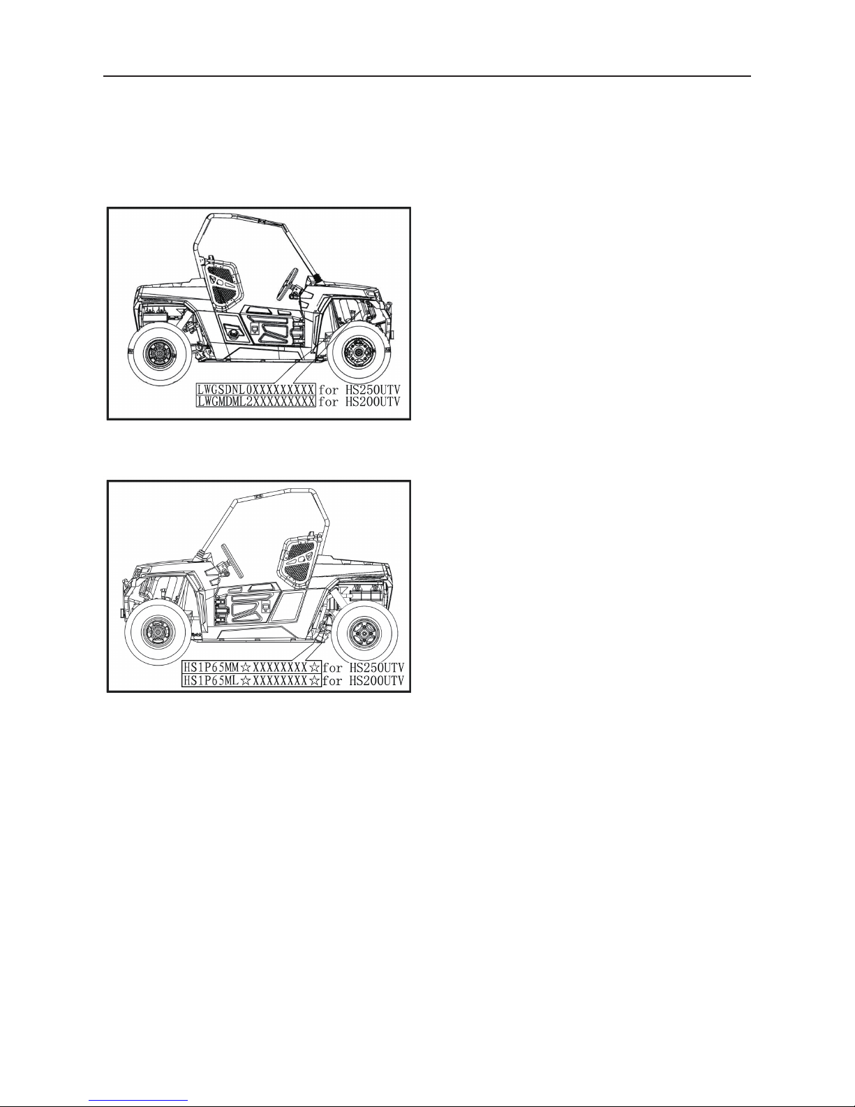
IDENTIFICATION CODE
Frame No.
Frame No. is carved on the right side of front
main frame
Engine No.
Engine NO. Is carved on the right side of the
engine, Figure.

-4-
GENERAL INFORMATION
- 4 -
SAFETY
Professional mechanics can work for years and never sustain a serous injury or mishap. Follow
these guidelines and practice common sense to safely service the utility terrain venires
1. Do not operate the utility terrain venires in an enclosed area venires The exhaust gasses contain
carbon monoxide. an odorless, colorless and tasteless poisonous gas. Carbon monoxide levels
build quickly in small enclosed areas and can cause unconsciousness and death in a short time.
Make sure to properly ventilate the work area or operate the UTV side
2. Never use gasoline or any extremely flammable liquid to clean parts. Refer to cleaning parts and
handling Gasoline Safely in this section
3. Never smoke or use a torch in the vicinity of flammable liquids, such as gasoline or cleaning
solvent.
4. If welding or brazing on the UTV the fuel tank to a safe distance at least 50ft.(15m) away.
5. Use the correct type and size of tools to avoid damaging fasteners.
6. Keep tools clean and in good condition. Replace or repair worn or damaged equipment.
7. When loosening a tight fastener, be guided by what would happen if the tool slips.
8. When replacing fasteners, make sure the new fasteners are the same size and strength as the
original ones.
9. Keep the work area clean and organized.
10. Wear eye protection anytime the safety of the eyes is in question. This includes procedures that
involve drilling, grinding, hammering, compressed air and chemicals.
11. Wear the correct clothing for the job. Tie up or cover long hair so it does not get caught in moving
equipment.
12. Do not carry sharp tools in clothing pockets.
13. Always have an approved fire extinguisher available. Make sure it is rated for gasoline (Class B)
and electrical (Class C) fires.
14. Do not use compressed air to clean clothes, the UTV or the work area. Debris may be blown into
the eyes or skin. Never direct compressed air at anyone. Do not allow children to use or play with
any compressed air equipment.
15. When using compressed air to dry rotating parts, hold the part so it does not rotate. Do not allow
the force of the air to spin the part. The air jet is capable of rotating parts at extreme speed. The
part may disintegrate of become damaged, causing serious injury.
16. Do not inhale the dust created by brake pad and clutch wear. These particles may contain
asbestos. In addition, some types of insulating materials and gaskets may contain asbestos.
Inhaling asbestos particles is hazardous to one’s health.
17. Never work on the UTV while someone is working under it.
Handling Gasoline Safely
Gasoline is a volatile flammable liquid and is one of the most dangerous items in the shop.
Because gasoline is used so often, many people forget it is hazardous. Only use gasoline as fuel
for gasoline internal combustion engines. Keep in mind when working on the machine, gasoline is
always present in the fuel tank fuel line throttle. To avoid a disastrous accident when working
around the fuel system, carefully observe the following precautions:
1. Never use gasoline to clean parts. Refer to Cleaning Parts in this section.

-5-
GENERAL INFORMATION
- 5 -
2. When working of the fuel system, work outside or in a well-ventilated area.
3. Do not add fuel to the fuel tank or service the fuel system while the UTV is near open flames,
sparks or where someone is smoking .Gasoline vapor is heavier than air, it collects in low areas
and is more easily ignited than liquid gasoline.
4. Allow the engine to cool completely before working on any fuel system component.
5. Do not store gasoline in glass containers. If the glass breaks, a serious explosion of fire may
occur.
6. Immediately wipe up spilled gasoline with rags. Store the rags in a metal container with a lid until
they can be properly disposed of, or place them outside in a safe place for the fuel to evaporate.
7. Do not pour water onto a gasoline fire. Water spreads the fire and makes it more difficult to put out.
Use a class B, BC or ABC fire extinguisher which are dedicated to extinguish the gasoline fire.
8. Always turn off the engine before refueling. Do not spill fuel onto the engine or exhaust system.
Do not overfill the fuel tank. Leave an air space at the top of the tank to allow room for the fuel to
expand due to temperature fluctuations.
Cleaning Parts
Cleaning parts is one of the more tedious and difficult service jobs performed in the home garage.
Many types of chemical cleaners and solvents are available for shop use. Most are poisonous and
extremely flammable. To prevent chemical exposure, vapor buildup, fire and serious injury, observe
each product warning label and note the following:
1. Read and observe the entire product label before using any chemical. Always know what type of
chemical is being used and whether it is poisonous and/or flammable.
2. Do not use more than one type of cleaning solvent at a time. If mixing chemicals is required,
measure the proper amounts according to the manufacturer.
3. Work in a well-ventilated area.
4. Wear chemical-resistant gloves.
5. Wear safety glasses.
6. Wear a vapor respirator if the instructions call for it.
7. Wash hands and arms thoroughly after cleaning parts.
8. Keep chemical products away from children and pets.
9. Thoroughly clean all oil, grease and cleaner residue from any part that must be heated.
10. Use a nylon brush when cleaning parts. Metal brushes may cause a spark.
11. When using a parts washer, only use the solvent recommended by the manufacturer. Make sure
the parts washer is equipped with a metal lid that will lower in case of fire.
Warning Labels
Most manufacturers attach information and warning labels to the UTV. These labels contain
instructions that are important to personal safety when operating, servicing, transporting and storing
the UTV. Refer to the owner’s manual for the description and location of labels. Order replacement
labels from the dealers or manufacturer if they are missing or damaged.
This manual suits for next models
1
Table of contents
Other Hisun Motorcycle manuals

Popular Motorcycle manuals by other brands

MV Agusta
MV Agusta Brutale 675 Workshop manual

APRILIA
APRILIA RSV MILLE - PART 1 1999 User manual content

Royal Enfield
Royal Enfield Himalayan 2018 owner's manual

SSR Motorsports
SSR Motorsports Lazer5 owner's manual

MOTO GUZZI
MOTO GUZZI 2005 Griso 1100 Use and maintenance book

KTM
KTM 85 SX 19/16 owner's manual


