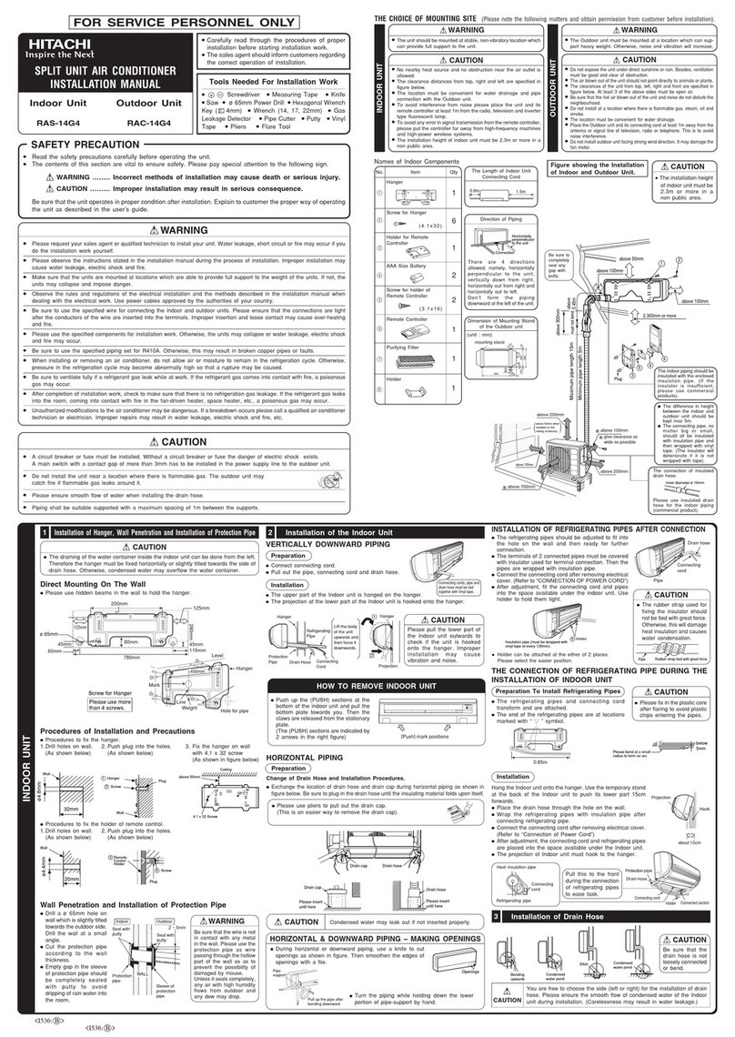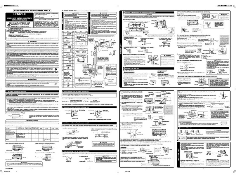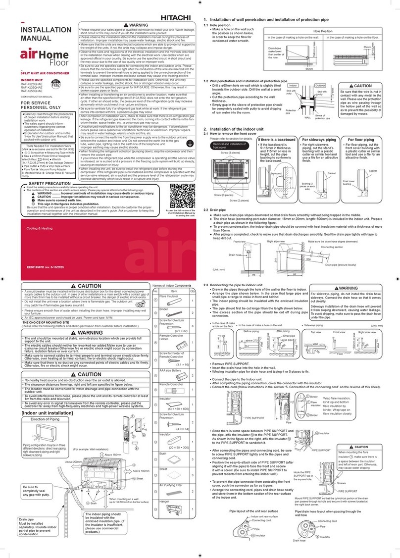
a Preparation of Pipe
•
Use
a pipe cutter to cut the copper pipe. B Pipe Connection
.1,CAUTI0N
In
case of removing flare nut of an Indoor unit, first remove a nut of small diameter side, or a seal cap
of big diameter side will fly out. Prevent water from entering into the piping when working.
~
~~--
Trimmingtool
Copper
pipe
'
~
Outer diameter Torque
N.m
of pipe (kgf.cm)
mm
(inch)
it.
CAUTION
~~t
Small dia. side 6.35 (1/4") 13.70 ~18.60 (140 ~190)
9.52 (3/8") 34.30 ~44.10 (350 ~450)
• Jagged edge will cause leakage. Large dia. side 12.7 (1/2") 44.10 ~53.90 (450 ~550)
• Point the side to be trimmed downwards during trimming
to
prevent copper chips from entering the pipe.
Wrench
~
/l4__
Torque
ff
)'~......_wrench 15.88 (5/8") 49.00 ~58.80 (500 ~600)
• Before flaring, please put
on
the flare nut. Small dia. side 6.35 (1/4") 19.60 ~24.50 (200 ~250)
Valve 9.52 (3/8") 19.60 ~24.50 (200 ~250)
head cap Large dia. side
D~
~A
Copper
pipe
• Recommend
to
use
R41
0A
flaring tool Valve core cap
12.7 (1/2") 29.40 ~34.30 (300 ~350)
15.88 (5/8") 29.00 ~31.00 (296 ~316)
12.30 ~15.70 (125 ~160)
Outer
Diameter
Thickness
Flare
tool
for
R41
0A
mm
(inch)
mm
Clutch
type
6.35 (1/4) 0.8 0.0 ~0.5
9.52 (3/8) 0.8 0.0 ~0.5
(
Lt
WARNING
I • THIS APPLIANCE MUST
BE
GROUNDED.
Procedures of Wiring
In
case that power
is
supplied
from
Indoor Unit
Indoor
Unit
Connecting
Cord
Detail of cutting the connecting cord
Indoor Unit
Green+
Yellow
(ground)
Control line
Lt WARNING
• The naked part
of
the wire core should be 10mm and fix
it
to
the terminal
tightly.
Then
try
to
pull
the
individual
wire
to
check
if
the
contact
is
tight.
Improper
insertion may
burn
the terminal.
• Be sure to use only power cables approved from the authorities
in
your
country.
If
the
supply
cord
is
damaged,
it
must
be
replaced
by
the
manufacturer,
its
seivice agent or similarly qualified person
in
order
to
to
avoid a hazard.
• Please refer
to
the following for wire connection
to
the terminals
of
the
units. The cabling must meet the standards
of
electrical installation.
• There
is
a
AC
voltage drop between the L and N terminals
if
the power
is
on.
Therefore,
before
servicing,
be
sure
to
remove
the
plug
from
the
AC outlet
or
switch
off
the main switch.
(~
________
G_a_s_L_ea_k_a_g_e_ln_s_p_e_c_t_io_n
________
)
L'.t,.WARNING
Amm
Please use gas leakage detector to check
if
leakage
Clutch
type
Wing
nut
type
occurs
at
the connection of Flare nut as
shown
on
the right. BURST HAZARD
Do
not
allow
air,
etc.
to
get
into
refrigerant
cycle
(piping)
1.0 ~
1.5
1.5 ~2.0
1.0 ~
1.5
1.5 ~2.0
If
gas leakage occurs, further tighten the connection
to
stop leakage. (Use the detector provided for
R410A)
RISK OF EXPLOSION
Compressor
must
be
stopped
before
removing
refrigerant
pipes.
All
service
valve
must
be
fully
closed
after
pumping
down
operation.
Wiring Of The Indoor Unit
• For wire connection of the indoor unit,
you
need
to
remove the front cover,
the low cover under the body of the unit and terminal cover.
• Remove the cover from the terminal base and screw the cable.
After remove the
screw and terminal
cover,
and
put
the
connecting cords and
fix the terminal cover
with
screw.
Method
to
remove
electrical
cover
• Remove
the
screw and electrical cover.
3
Cord
band
• Insert the connecting cord
(1,
2,
3)
from the back of unit.
• Fixed
the
wire to terminal wires firmly
as
shown
as
below.
Electrical
cover
Sere Connecting
cord
!l
D
.1, WARNING
• Leave some space
in
the connecting cord for
maintenance purpose and
be
sure
to
secure it
with the cord band.
• Secure the connecting cord along the coated part
of the wire using the cord band.
Do
not exert
pressure
on
the
wire
as
this may cause overheating
or
fire.
How
to
connect
the
optional
parts
(Dry
contact, H-Link/Wi
Fi
(optional},
Wired
remote, Run status)
• For cable connection
to
control
P.W.B.,
you
need
to
remove front cover and electrical box cover.
Each connecting location
is
as
below.
G)
Dry contact:
CN6
® H-LINK/Wi
Fi:
CN7
@ Wired Remote Controller: CN18
@)
Run
status:
CNS
• Please check and confirm manuals attached
to
each
optional parts for more connection details.
•
You
can refer
to
this installation manual how to
remove and re-attach the front cover.
• Please
be
careful not
to
damage lead wires by
edge of plate when connecting the optional parts.
CN7
a Insulation
And
Maintenance Of Pipe Connection B Installation Of Remote Controller ( How to remove the front cover ) ( How to attach the front cover )
• The connected terminals should
be
completed sealed with heat insulator
and then tied
up
with rubber strap.
• Please tie the pipe and power line together with vinyl tape
as
shown
in
the figure showing the installation of indoor and outdoor units. Then fix
their position with holders.
•
To
enhance the heat insulation and to prevent water condensation, please
cover the outdoor part of the drain hose and pipe with insulation pipe.
• Completely seal any gap with
putty.
Insulation
material
for
pipe
connection
~~
Sleeve
of
protection~ipe
/
'i
:·:
,:
Putty
:..
Putty
:i
::
El
Power Source And Operation Test
( Power Source )
.1, CAUTION
• Please use a new socket. Accident may occur due
to
the use of old
socket because of poor contact.
• Please plug
in
and then remove the plug for 2 - 3 times. This
is
to
ensure that the plug is completely plugged into the socket.
• Keep additional length for the power cord and
do
not render the plug
under external force as this may cause poor contact.
•
Do
not fix the power cord with U-shape nail.
( Operation Test )
• Please ensure that the air conditioner is
in
normal operating condition
during the operation test.
• Explain
to
your customer the proper operation procedures as described
in
the user's manual.
<IA2156:@>
• The remote controller can
be
placed
in
its holder which
is
fixed
on
wall or beam.
•
To
operate the remote controller
at
its holder, please ensure that
the
unit can
receive signal transmitted from the controller
at
the place where the holder
is
to
be
fixed. The unit will beep when signal
is
received from
the
remote controller.
The signal transmission
is
weaken by the florescent light. Therefore, during the
installation of the remote control holder, please switch
on
the light, even during
day time,
to
determine
the
mounting location of the holder.
The controller should
be
insert from top into bottom side of the holder
as shown
in
figure
below.
~
J
~
Romom
c,,.,m""
b-
Screw (2 pieces)
~
Holder for Remote Controller
• How to check pipe bending.
-Compare bended pipe with the picture below.
-
If
bended pipe
is
not good enough, cut bended area and bend
it
again.
all areas are smooth,
no
notching area
r==========~/··1
I '
s.
~============================================s=-~-~.,J
\_"'t
t
r"'
CD
CD
CD
CD
Remove the caps and unscrew at lower
portion of the front cover.
® ® ®
® Firmly press 4 hooks at top of front cover
by
tools until the hook release from slot
® Pull the front cover to front side.
®
@
©
no
scratch or mark inside
all have the same length
CD
®
@
there
are
scratches around bending area
crack
TI
I I
@ phase of bending
is
too long different length
® slanting
CD
sample of bending pipe cannot
be
used
CD CD
CD
CD
~
+ + + I
CD
To
assemble front cover back to the unit,
certainly hook at upper portion (4 places).
(Li
J
~f
t t
@ ® @ ® @
® Insert the bottom of front cover into the
slot at "PUSH" marking
and
ensure bottom
area
is
align from left to right.
® Tighten the screw and cover by caps
(3
places)
TI
i: l
Q
