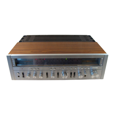
Hitachi SR-804 User manual

HITACHI
SERVICE
MANUAL
English
N
152
Deutsch
O.
Francais
ae
Europe,
U.K.,
Australia,
Asia
rang
&
Latin
American
countries
FEATURES
Audio
Section
1.
oonw
ooh
wh
Newly
Developed
High-Efficiency
High-Power
Audio
Amplifier
(Dynaharmony
Amplifier)
.
All-stage
Direct-connection
OCL
Amplifier
.
Electronic
Protection
Circuit
.
New
[Cs
in
the
Equalizer
and
Pre-amplifier
.
Separate
Type
Power
Meters
(L
and
R
Channels}
.
Tape
Dubbing
.
Two
Speaker
Systems
Connection
.
Coaxial
Type
VOLUME
and
BALANCE
Control
.
A
Low
Filter
and
a
High
Filter
MERKMALE
Audio-Abschnitt
1.
2.
3.
.
Neue
integrierte
Schaltung
im
Entzerrer
und
I
OD
.
Getrennte
Leistungspegel-Anzeigen
Neuentwickelter
Hochleistungs-
Audioverstarker
(Dynaharmony
Verstarker)
Vollstufiger,
direkt
gekoppelter
OCL-Verstarker
Elektronikschutzschaltung
Vorverstarker
(L
und
R
Kanal)
.
Bandaufnahme
vom
Original
.
Anschlu&
fiir
zwei
Boxenpaare
.
Koaxiale
Lautstarke-(VOLUME)
und
BALANCE-
Regler
.
Tiefen-und
Hohenfilter
Tuner
Section
1.
Dual
Gate
MOS
FET
for
High
Quality
FM
Tuner
2.
High
Selectivity
and
Low
Distortion
IF
Amplifier
Using
IC
and
3
Ceramic
Filters
3.
Quadrature
Detection
4,
Phase-Locked
Loop
for
FM/MPX
Circuit
5.
A
Ceramic
Filter,
IC
in
AM
Tuner
6.
Two
Large
Easy-to-read
Meters
and
a
Large-
sized
Fly-wheel
Tuning
Knob
Rundfunkempfangsteil
1.
Doppelsteuer-MOS-FET
fiir
den
hochwertigen
UKW-Tuner
2.
ZF-Verstarker
mit
groRer
Selektivitat
und
geringem
_
Klirrfaktor,
der
mit
ICs
und
3
Keramikfiltern
bestiickt
ist.
3.
Phasenschieberkreis
4.
Phasenstarre
Schleife
fiir
die
UKW/MPX-Schaltung
5.
Keramikfilter,
integrierte
Schaltung
im
Tuner
6.
Zwei
groBe,
gut
ablesbare
Me8instrumente
und
groRdimensionierter
Schwungrad-Abstimmknopf
STEREO
RECEIVER
September
)
978

ficateur
‘avhahaanoniaiiel
2.
Amplificateur
a
circuit
OCL
et
4
connexion
directe
pour
tous
fes
étages
3.
Circuit
électronique
de
protection
4.
De
nouveaux
circuits
intégrés
dans
I’égalisateur
et
dans
le
pré-amplificateur
5.
Indicateurs
de
puissance
séparés
(Canaux
gauche
(L)
et
droit
(R))
6.
Copiage
de
bande
7.
Connexion
de
deux
enceintes
8.
Commande
d’équilibrage
(BALANCE)
et
de
VOLUME
de
type
coaxial
9.
Filtre
des
aigués
et
filtre
des
graves
(1)
(2)
IMPORTANT
NOTICES
When
measuring
the
power
output
or
listening
to
program
source
with
the
4-OHMS
load
impedance,
do
not
drive
the
Model
SR-804
at
full
power
for
a
long
period
of
time.
When
using
the
mode!
with
a
continuous
output
of
over
100
watts,
the
protection
indicator
will
light
up
and
the
sound
will
sometimes
be
interrupted.
This
does
not
indicate
a
breakdown.
In
such
cases,
turn
off
the
power,
turn
down
the
volume
Seve!
and
then
wait
30
seconds
before
switching
the
power
back
on
again.
Note:
POWER
meter
indication
When
the
impedance
of
speakers
is
8
ohms,
the
scales
of
the
meters
express
the
power
output
in
Watts.
When
the
imped-
ance
of
the
speakers
is
only
4
ohms,
the
actual
output
is
double
the
value
indicated
on
the
meters.
For
example,
if
the
‘pointers
point
to
$0.W
on
the
scales,
then
the
actual
output
is
100
W,
WICHTIGE
HINWEISE
Wenn
Sie
die
Leistungsabgabe
messen
oder
der
Wiedergabe
von
einer
Programmquelle
mit
4
Ohm
Verbraucherimpedanz
zuhéren,
lassen
Sie
das
Modell
SR-804
nicht
mit
voller
Leistungsabgabe
iiber
einen
langeren
Zeitraum
hinweg
laufen.
Wenn
das
Modell
SR-804
mit
einer
kontinuierlichen
Leistung-
sabgabe
von
mehr
als
100
W
betrieben
wird,
leuchtet
die
Schutz
schaltungs-Leuchtanzeige
auf,
und
der
Ton
wird
manchmal
abgeschaltet.
Dies
ist
jedoch
kein
technisches
Versagen.
In
solchen
Fallen
die
Stromzufuhr
unterbrechen,
Lautstarkepegel
verringern
und
etwa
30Sekunden
warten,
bevor
die
Stromzufuhr
wieder
eingeschaltet
wird.
.
ZUR
BEACHTUNG:
Leistungspegel-Anzeige
(POWER)
Betragt
die
Lautsprecherimpedanz
8
Ohm,
zeigen
die
Skalen
den
Ausgangspegel
in
Betrigt
die
Lautsprecherimpedanz
nur
4
Ohn,
its
die
tatsichliche
Ausgangsabgabe
doppelt
so
hoch
wie
der
angezeigte
Wert.
Zeigt
der
Skalenzeiger
z.B.
50
W
an,
so
betragt
der
tatsichliche
Wert
100
W.
AVERTISSEMENTS
IMPORTANT
Quand
on
mesure
la
puissance
en
sortie.ou.que
l’on
écoute
des
sources
de’
programmes
avec
l’impédance
de
charge
de
4-OHMS,
ne
pas
faire
fonctionner
le
modéle
SR-804
a
pleine
puissance
pendant
une
longue
période
de
temps.
Quand
on
utilise
cet
appareil
avec
un
débit
continuel
de
puissance
dépassant
100
watts,
le
voyant
de
protection
peut
s’allumer
et
le
son
peut
quelquefois
s‘interrompre.
Ceci
ne
veut
pas
dire
qu’il
y
ait
une
panne,
Dans
de
tels
cas,
couper
l’alimentation,
baisser
le
niveau
du
son,
et
puis
attendre
environ
30
secondes
avant
de
réalimenter
l'appareil.
Remarque:
Indication
du
compteur
de
puissance
(POWER)
Quand
limpédance
dés
enceintes
-est
de
8
‘ohms,
“fes
échelles
des
indicateuys‘expriment
le*
débit
de
puissance
en.
Watts.
Quand
fimpédance:des
enceintes
n'est
que
de
4:
ohms,
le
débit
de
puissance
réel
est
le
double
de
la
valeur
affichée
sur
les
indicateurs.
Par
exemple,
si
les
curseurs
4.
5.
6.
(3)
(4)
Bho
ia
élevée
Amplificateur
Fl
4
faible
niveau
de
distorsion
et
a-haute
sélectivité
employant
des
circuits
inté-
grés
et
trois
filtres
céramiques
Détection
quadriphonique
Boucle
a
blocage
de
phase
pour
le
circuit
FM/MPX
Un
filtre
céramique,
circuit
intégré
dans
le
tuner
AM
Deux
indicateurs
4
lecture
facile
et
un
bouton
de
syntonisation
utilisant
un
volant
de
large
dimension
The
Model
SR-804
has
two
types
of
electronic
protection
circuits;
a
shut-down
circuit
and
current
limiter
circuit.
If
the
shut-down
circuit
is
actuated,
the
output
of
the
amplifier
is
cut
off.
When
only
the
current
limiter
circuit
is
actuated,
the
operation
of
the
power
amplifier
is
not
shut
down.
A
tape
deck
being
used
may
be
susceptible
to
induction
from
the
receiver,
although
this
depends
on
the
type
of
tape
deck,
and
there
may
be
a-hum
sound.
In
such
cases,
install
the
tape
deck
in
a
location
where
it
will
not
be
susceptible
to
the
induction.
(For
instance,
place
the
tape
deck
on
the
right
of
the
receiver
when
viwed
from
the
front).
Do
not
place
the
tape
deck
on
top
nor
on
the
left
of
the
receiver
since
this
will
impair
the
receiver's
performance.
Das
Modell
SR-804
ist
mit
zwei
Arten
von
elektronischen
Schutzschaltungen
ausgestattet,
einer
Abschaltvorrichtung
und
einer
Strombegrenzerschaltung.
Wird
die
Abschaltvorrichtung
aktiviert,
wird
die
Leistungsabgabe
des
Verstarkers
unterbrochen.
Wird
nur
die
Strombegrenzerschaltung
aktiviert,
wird
der
Betrieb
des
Leistungs-
verstarkers
nicht
unterbrochen.
Ein
in
Betrieb
befindliches
Tonbandgerdt
koénnte
unter
Umstaénden
empfindlich
auf
Induktion
vom
Empfanger
reagieren,
und
es
kénnte
induziertes
Brummen
auftreten.
In
solchem
Fall
das
Tonbandgerat
an
einem
Platz
aufstellen,
wo
es
von
Induktionen
nicht
erreicht
werden
kann.
(Sie
kénnen
das
Tonbandgerat
z.B.
an
der
rechten
Seite-
von
vom
gesehen
-
des
Empfangers
aufstellen.)
Das
Tonbandgerat
weder
auf,
noch
an
die
linke
Seite
des
Empfingers
stellen,
weil
dadurch
die
Leistung
des
Empfangers
beeintraichtigt
wird.
indiquent
le
point
50
watts
sur
les
échelles,
le
débit
réel
se
monte
a
100
watts.
Le
modéle
SR-804
est
équipé
de
deux
types
de
circuits
de
protection
électronique;
un
circuit d’arrét
total
et
un
circuit
de
limitation
de
courant.
Dand
le
cas
ob
le
circuit
de
coupure
totale
est
activé,
ta
sortie
de
Pamplificateur
continue
4
fonctionner.
Une
platine
de
magnétophone
en
fonctionnement
est
susceptible
d’étre
induite
par
le
récepteur,
bien
que
cela
dépende
du
type
de
platine
de
magnétophone
utilisé,
et,
de
ce
fait
un
certain
ronflement
peut
apparaitre.
Dans
de
tels
cas,
installer
la
platine
de
magnétophone
dans
un
endroit.
o4
elle.ne
sera
pas
susceptible
d’¢tre
induite,
(Par
exemple,
installer
la
Platine
a
droite
du
récepteur
quand
on
les
regarde
de
face.)
Ne
pas
placer.
la
platine
de
napaetophane
sur
ou
a
gauche
du
récep-
teur
car
cela
pourrait
affecter
les
performances
du
récepteur.
|
j
}
|
:

HITACHI
SR-804
DISASSEMBLY
AND
REPLACEMENT:-ZERLEGUNG
UND
AUSTAUSCH-
DEMONTAGE
ET
REMONTAGE
@
Removing
the
top
cover,
front
panel
&
bottom
plate
e@
Ausbau
der
oberen
Abdeckung,
der
Fronttafel
und
der
Bodenplatte
©
Déposer
ie
couvercle
supérieur,
le
panneau
frontal
et
la
plaque
inférieure
Top
cover
Oberen
Abdeckung
Couvercle
supérieur
LAMP
P.WB.
Lampe
P.
WB.
3$x
8DT(x
2)
Fig.
1
Hexagonal
wrench
;
Front
panel
Bottom
plate
Abb,
1
Sechskantschlissel
Fronttafel
Bodenplatte
Clé
a
téte
six
pans
Panneau
frontal
Plaque
inférieure
@
Removing
the
printed
wiring
boards
and
output
transistors
@
Ausbau
der
Leitter
platten
und
Leistungstransistoren
@
Déposer
der
plaquettes
4
circuit
imprime
et
transistors
de
sortie
Output
transistors(x4)
Leistungstransistor(x
4)
Transistors
de
sortie
(x4)
34(«8)
3x
lODT(
x
2)
3¢x6DT(x
2).
.
34x
6DT(
x
4)
»
3¢x
10(x8)
NY
Plaquette
de
circyits
Se)
s
J
EVA
pp
q
Si
J
3¢x
8DT(x
4)
SNe
eS,
7
PRO
PWerstarker
WB.
XS
MAIN
PW
B.
iemecenr
as
Dee
SEN
ERE)
aleve
WE
A
44
S
hy
44x
|2DT(x
4
fe
<3
SI
$
(x4)
ane
7
sh
3¢x6DT(x
4)
Fig.
2
>
Fig.
3
Abb.
2
Abb.
3
ane
ee

HITACHI
SR-804
DIAL
CORD
SETTING
-
SKALENSEILEINSTELLUNG
-
EQUIPEMENT
DE
CADRAN
Pulley
Riemenscheibe
End
Poulie
Ende
Fin
Shaft
Spring
pete,
Feder
0.5-1.5mm
Ressort
Start
ye
Set
to
between
@and
©
.
Anlassen
Zwischen
©
und
©
einstellen.
Mise
en
marche
eave
te:
ae
Axe
d’accord
3windungen
3tours
Fig.
4
GENERAL
ALIGNMENT
INSTRUCTION:
ALLGEMEINE
AUSRICHTANLEITUG
-
V.C.0
FREQUENCY
ADJ.
SEPARATION
ADJ.
TP.S
V.C.0
FREQUENCY
CHECK
|Frequenzeinstellung
des
spannungsgeregelten
Trennscharfen-Einstellung
Prufpunkt.
5
(Frequenzprifung
de:
Réglage
de
fréquence
d'oscillateur
_szillators}
:
Réglage
de
séparation
spannungsgeregelten
AM
ANT.
COIL
AM
TRACKING
ADJ
7P3
FM
DISCRI
OUT
FM
DISCRI.
ADA.
aie
‘
AM-Antennenspule
Prufpunkt
3
(UKW-Dekoder-Ausgang)|
7}
UKW-Dekoder-Einstellung
ontroie
ge
frequence
AM
Bereichseinstellung
Sortie
discri,
FM
TP.3
Réglage
de
discri.
FM
oscillateur
TP.5
Réglage
de
bobine
d'antenne
AM
FM
OSC.
CAP.
UKW-Oszillator-Kondensator|
Capuchon
osc.
FM
FM
OSC. COIL
UKW-Oszillatorspule
Bobine
osc.
FM
]
sj
__
ws)
c
a
TUNING
M.1(+)
2:
Abstimmung
M.1(+
#3
as
Accord
M.1(+)
<¢
&
FM
IF
ADJ.
TUNING
M2(—)
3s
3
UKW-ZF
Einstellung
Abstimmung
M.2(—}
8
Reglage(Fi
FM)
Accord
M.2(—)
5
TP.1
GENESCOPE
OUT
(0)
Priifpunkt
1
(Qszilloskop-Ausgang)
Sortie
générateur
de
signal
TP.1
:
FM
ANT.
COIL
FM
OUTPUT
LEVEL
ADJ.
KW-Antennenspule
\UKW
-Ausgangspegel-Einstellung
jae
Babine
d'antenne
FM
Régiage
de
niveau
de
sortie
FM
ine
FR
Eh
Bob
R
FM
TP.4
AM
OUT
GENESCOPE
IN
CTISI(ANT)
AM
TRACKIN
CTLOI(ANT.)
FM
TRACKING
Prifpunkt
4(AM-Ausgang
“Oszilloskop-Eingang)
AM
OSC.
COIL
CT151
(Antenne)
AM-Bereich
CT101
(Antenne)
UKW-Bereich
Sortie
AM
TP.4
entrée
générateur
de
signal
AMOszillatorspule
CT251(Ant)
Poursuite
AM
CT101(Ant.)
Poursuite
FM
TP.2
FM
METER
OUT
GENESCOPE
IN
Bobine
osc.
AM
eT
102(RF)
FM
TRACKING
Fig.
5
Priifpunkt
2
(UKW-Anzeige-Ausgang
‘Oszilloskopeingang)
T102(HF)
UKW-Bereich
Abb
5
Sortie
d'indicateur
FM
TP.2
entrée
genérateur
de
signal’
1102(FR)
Poursuite
FI

HITACHI
SR-804
FM
TUNER
ALIGNMENT
-
ABGLEICH
DES
UKW-TUNERS-
REGLAGE
DU
CIRCUIT
SON
Condition
Kondition
Conditions
Sweep
Generator
Wobbelgenerator
Générateur
de
balayage
VTVM
Voltmetre
electronique
Function
:
Volume:
Modulation:
Funktion:
Lautstarke:
Modulation:
Fonction
:
Volume
:
Modulation:
FM
Minimum
400Hz
100%
{unless
otherwise
notified)
UKW
Minimum
400Hz
.100%
(wenn
nicht
anderes
angegeben)
FM
Reglage
silencieux
FM
au
minimum
400Hz
100%(a
moins
qu’
il
en
soit
specifie
autrement),
FM
Muting
OFF
UKW-Stummabstimmung:
Aus
OFF
Signal
Generator
SignalVeneretor
©
Générateur
de
signaux
Frequency
Counter
Frequenzzahler
Frequencemetre
Connection
Anschliisse
Oscilloscope
Distortion
Meter
Klirrmesser
Distorsionmétre
Sequence
Folge
Ordre
Connexion
Input
Eingang
Entrée
®
©
Adjust
for
Einstellung
fir
Reglage
pour
Adjust
Einstellpunkt
Reglage
D
Indication
Indikation
Indication
Q
©
IF
Amp.
Z¥-Verst.
Amplificateur
de
fréquence
intérmediaire
"Ss"
curve
S-Kurve
Courbe
S
Covering
Abstimmung
Guipage
Tracking
Nachfiihrung
Alignement
Discri.
Diskriminator
Discriminateur
Distortion
Verzerrung
Distorsion
Output
Ausgang
Sortie
Separation
Séparation
out
Ausgang
TP.1
Sortie
om—(Z8)
1K
ANT,
Terminal
Antenne
Klemme
Borne
d'antenne
©-
'400Hz
30%
Mod.
Aussteuerung
Modulation
Non-modulated
Nicht
meduliert
Sans
modulation
Reh
400Hz
46%
Mod.
Rechter
Kanal,
400Hz,
46%
Modulation
Canal
droit
:
400Hz,
46%
de
modulation
Pilot
8%
Mod,
Pilotton,
8%
Modulation
Signal
pilote
8%
de
modulation
in
Eingang
TP.3
Entrée
ewni
100K
0.
lu
REC
out
or
SP
out
REC-oder
Lautsprecher
-Ausgang
Sortie
d'enregistrement
ou
sortie
haut-parleur
T202
lower
:
"S"
curve
upper
:
Straight
line
Unten
;:
S-Kurve
Oben
:
Gerade
linie
inferieure
:
courbe
ngit
superieure
:
ligne
droite
J
Ve
Straight
line
Gerad
linie
Ligne
droite
S\r
T101,
102
V
max.
CT101,
102
Repeat
4
Schritte
4
Repéter
4
REC
out
or
SP
out
REC-oder
Lautsprecher-
Ausgang
Sortie
d'enregistrement
-ou
sortie
haut-parleur
Dist.
S654
REC
out
REC-Ausgang
¢
y
Sortie
d'enregistrement
T202
(lower)
(Unten)
(inférieure)
Pointer
:
Aiguille
:
[oho
|
center
without
signal
Zeiger
:
Mittelstellung
che
ignal
au
centre
sans
signal
T202
(upper)
(ober)
(supérieure)
Distortion
min;
CAUTION
(1)
lVerzerrungen
minimal
Vorsicht
(1)
Distorsion
minimum
ATTENTION
(1)
150mV
*+1dB
©
@
TP.5
eS
|
76kHz
+100Hz
REC
out
or
SP
out
REC-oder
Lautsprecher-
Ausgang
Sortie
d'enregistrement
o
13.
SD
LP.
F.
Leh
out
MIN
CAUTION
(2)
Ausgang
des
linken
Kanals
:
Minimum
Vorsicht
(2)
Sortie
canal
gauche
Min.
Attention
(2)

HITACHI
SR-804
RR
CAUTION
1.
Asthe
result
of
the
adjustment
step
6,
the
best
point
of
adjustment
from
step
5
will
be
shifted
a
bit.
Repeat
the
adjust-
ment
of
step
5
and
6
until
the
deterioration
becomes
minimum
and
the
pointer
of
tuning
meter
is
in
its
center.
2.
Optimize
R238
so
that
the
leak
level
of
the
L
ch
signal
is
equal
to
that
of
the
R
ch
signal.
VORSICHT
1.
Aufgrund
der
in
Schritt
6
beschriebenen
Einstellung
kann
sich
der
in
Schritt
5
beschriebene,
optimale
Einstellpunkt
um
etwas
verschieben.
Die
Einstellungen
der
Schritte
5
und
6
daher
mehrmals
wiederholen,
bis
minimale
Abweichung
gewahrleistet
ist
und
die
Anzeigenadel
des
Abstimminstrumentes
in
Mittelposition
verweilt.
2.
R238
so
einjustieren,
da
der
Ubersprechpegel
des
linken
gleich
dem
des
rechten
Kanalsignales
ist.
ATTENTION
1.
A
la
suite
du
réglage
décrite
en
6,le
meilleur
réglage
décrit
en
5
sera
légérement
décalé.
Renouveler
les
réglages
5
et
6
jusqu’a
ce
que
les
détériorations
soient
minimum
et
que
l’aiguille
de
l’indicateur
d’accord
soit
en
position
centrale.
2.
Rendre
R238
optimum
pour
que
le
niveau
de
créte
du
signal
de
canal
gauche
(L)
soit
égal
4
celui
du
canal
droit
(R).
AM
TUNER
ALIGNMENT
-
ABGLEICH
DES
AM
TUNER:
REGLAGE
DU
TUNER
AM
Condition
Function
:
AM
Kondition
Funktion
:
AM
Conditions
Fonction
:
AM
Modulation:
400Hz
30%
Connection
Anschiiisse
Connexion
Adjust
for
Einstellung
fir
Reglage
pour
Sett:
Binstellung
Montage
Sequence
Folge
Ordre
Output
Ausgang
Sortie
©.
©
in
Eingang
entrée
Adjust
Einstelipunkt
Réglage
D
Indication
Indikation
Indication
ee
Te
CAUTION(1)
VORSICHT
(1)
ATTENTION(1)
Tuning
Abstimmanzeige|
signal
out
Ausgang
Sortie
IF
Amp.
ZF-Verst.
Amplificateur
de
fréquence
intérmediaire
TP.4
ow
“f
CT151
100K
0.
1n
Covering
Abstimmung
Ferrite
Antenna
Guipage
Ferritkernantenne
Antenne
en
ferrite
600kHz
L153
4
REC
out
or
SP
out
Sortie
d’enregistrement|
1
490KHz
lou
sortie
haut-parleur
1400kHz
CT152
L152
Tracking
Nach
fihrung
Alignement
CAUTION
oof
Ferrite
Antenna
Ferritkernantenne
Antenne
ferrite
1400kHz
1400kHz
1,
In
step
1,
set
the
capacitance
of
the
variable
capacitor
to
minimum
and
ad-
just
red
and
blue
cores
of
T151
so
that
the
wave
form
is
as
shown
in
Fig.
6.
As
T151
contains
a
455
kHz
ceramic
filter,
sometimes
the
center
of
the
marker
will
not
correspond
to
that
of
the
wave
form.
In
this
case,
neglect
the
marker.
After
adjusting
as
above,
increase
the
out-
put
level
of
the
sweep
generator
and
adjust
T151
again
so
that
the
top
of
the
wave
form
A
(indicated
in
Fig.
7)
will
be
flat
and
wide.
2.
In
carrying
out
adjustment
described
in
step
2
and
3,
repeat
the
adjust-
ment
so
that
the
output
at
600
kHz
and
1400
kHz
become
maximum.
VORSICHT
CT151
Fig.
6
Abb.
6
V
max.
CAUTION(2)
VORSICHT
(2)
ATTENTION
(2)
Fig.
7
Abb.
7
1.
In
Schritt
1
ist
die
Kapazitanz
des
Regelkondensators
auf
ein
Minimum
einzustellen;
die
roten
und
blauen
Kerne
von
TIS1
so
einjustieren,
daB
die
in
Abb.
6
gezeigte
Wellenform
erhalten
wird.
Da
T151
auch
ein
455-kHz-Keramikfilter
enthalt,
kann
es
vorkommen,
das
manhcmal
die
Mitte
der
Anzeige
nicht
mit
der
Wellenamplitude
iibereinstimmt.
In
6

HITACHI
SR-804
oe
ee
ee
.
diesem
Falle
ist
die
Anzeige
nicht
zu
beachten.
Nach
der
obigen
Einstellung
den
Ausgangspegel
des
Wobbelgenerators
erhéhen
und
T151
nochmals
einstellen,
so
daf§
der
Maximalwert
der
Welle
an
Punkt
A
(gezeigt
in
Abb.
7)
eine
Ab-
flachung
und
Verbreiterung
erfahrt.
2.
Die
in
den
Schritten
2
und
3
aufgefiihrten
Einstellungen
durchfihren
und
mehrmals
wiederholen,
bis
der
Ausgangs-
pegel
eines
600
kHz
bzw.
1.400
kHz
Signals
einen
Maximalwert
annimmt.
ATTENTION
1.
Dans
le
point
1,
régler
la
capacitance
du
condensateur
variable
sur
la
position
minimum
et
ajuster
les
noyaux
rouge
et
bleu
de
T151
pour
que
la
forme
d’onde
soit
identique
4
celle
indiquée
sur
l’illustration
(Fig.
6).
Etant
donné
que
T151
contient
un
filtre
céramique
de
455
kHz,
il
peut
arriver
que
le
centre
de
l’indicateur
ne
corresponde
pas
a
la
forme
d’onde.
ae
Si
le
cas
se
présente,
ne
pas
tenir
compte
de
la
position
de
l’indicateur.
Aprés
avoir
effectué
les
réglages
cidessus,
augmenter
le
niveau
de
sortie
4
Paide
d’un
générateur
de
balayage
et
ajuster
T151
une
nouvelle
fois
pour
que
le
haut
de
la
forme
d’onde
A
(illustrée
par
la
Fig,
7)
soit
plate
et
large.
2.
En
effectuant
le
réglage
décrit
en
2
et
3,
répéter
le
réglage
pour
que
la
sortie
4
600
kHz
et
1400
kHz
soit
maximale.
Genescope
Oszilloskop
?
.
.
Générateur
d'oscillation
Model
SR-804
Fig.
8
FM
IF
Discriminator
and
AM
IF
alignments
(FM:
Step.
1,
2;AM:Step.1)
Abb.8
UKW-ZF~Diskriminator
und
AM-ZF-Abgleich
(UWK:Schritte.1,2,AM:Schritt
1)
Fig.8
Réglages
de-discriminateur
FM
IF
et
AM
IF
(Operations
!,2
FM
et
:
AM)
AC
Voltmeter
AM
Signal
generator
Wechselspannungsmesser
AM
Signalgenerator
Voltmetre
a
courant
:
Générateur
de
signal
AM
Loop
antenna
alternatif
Oscilloscope
Rahmenantenne
Model
SR-804
Antenne
en
boucle
Fig.9
AM
frequency
covering
and
Abb.9
AM-Bereich-und-
Fig.9
Régiages
de
poursuite
et
tracking
alignments
Nachfiihrungsabgleich
détendue
de
fréquence
(Step.2and
3)
(Schritte
2und
3)
AM(Operations
2et
3)
AC
Voltmeter
FM
Signal
generator
Wechselspannungsmesser
UKW
Signalgenerator
:
Voltmetre
a
courant
°
Générateur
de
signal
FM
alternatit
Oscilloscope
Model
SR-804
ANT.DUMMY
Kunstantenne
ANT.
TERMINAL
“ati
Antennenanschiu8
Antenna
fictive
Borne
O
@antenne
4)
7
O
Fig.10
FM
frequency
covering
,tracking
and
other
alignments
(Step.
3to7)
Abb.
IO
UKW-Bereich~,-Nachfthrungs-und
andere
Abgleiche
(Schritte
3bis7)
Distortion
meter.
Fig.10
Réglages
de
poursuite,d’étendue
de
frequence
Klirrmesser
FM
et
autres
Distortiométre
(Operations
3
G7)

HITACHI
SR-804
Frequency
counter
Fig.1f
FM
MPX
76kHz
adjustment
Model
SR-804
Frequenzzahler
(Step.8)
Frequencemetre
Abb.
1!
UKW-Dekoder
76-kHz-Abgleich
(Schritt
8)
Fig.
[1
Réglage
de
76kHz
MPX
FM
Operation
8
FM
Strereo
Signal
FM
Signal
generator
pareratee
UKW
Signalgenerator
‘
AC
Voitmeter
alae
Générateur
de
signal
FM
Wachee
leponnungamiessar
eee
Voltmétre
@
courant
alternatif
Générateur
de
signal
stéréo
FM
Model
SR-804
ANT.DUMMY
Kunstantenne
pee
ANT.
TERMINAL
Antenne
fictive
Antennenanschius
©
Fig.
12
FMMPX
alignments(Step.9)}
Abb.
12
UKW-Dekoder—Abgleich(Schritt
9)
:
Fig.12
Réglage
de
MPX
FM(Operation
9)
Oscilloscope
AUDIO
CIRCUIT
ALIGNMENT
ABGLEICH
DES
AUDIO-SCHALTKREISES
REGLAGE
DU
CIRCUIT
SON
R751L
R751R
MAIN
P.W.B.
‘Hauptverstarker
P.W.B.
Aliméntation
P.W.B.
@@bL
CHANNEL
Oa@
©
R
CHANNEL@
@
\
Linker
kanal
a
Rechter
kanal
/
L
canal
R
canal
ADJUSTING
POINT
ADJUSTING
POINT
Me8punkt
Meg
punkt
Point
de
réglage
Point
be
réglage
Fig.
13
Abb.
13
Test
conditions
FUNCTION
......
Free
VOLUME........
Minimum
Item
Measuring
instrument
Idle
current
DC
voltmeter
Versuchsbedingung
FUNCTION
.....
Frey
VOLUME
........
Minimum
Benennung
Mef
instrument
Blindstrom
’
Gleichspannungsmesser
Conditions
pour
les
essais
FUNCTION
.....
Libre
VOLUME
Apparel
de
mesure
V
stre
ADC.
a
limV
+
4,4
mV

HITACHI
SR-804
eee
METER
ADJUSTMENT
-
ABGLEICH
DES
ANZEIGEINSTRUMENTES
:
REGLAGE
DE
COMPTEUR
Meter
sensitivity
adjustment
.
Set
the
volume
control
to
(ce)
position.
.
Set
the
power
switch
to
ON.
(FUNCTION
switch:
AUX)
.
Connect
the
OSC
output
to
the
AUX
input.
(Frequency:
1
kHz)
.
Connect
the
AC
voltmeter
to
the
speaker
terminals.
.
Adjust
the
OSC
output
level
and
volume
control
so
that
the
output
voltage
at
the
speaker
terminals
is
12.65V
rms
without
speaker
connections.
nA
pBWNF
@
Measuring
instrument
|
Adjust
Deviation
of
needle
:
Oscillator
Meter
adjustment
AC
volisnctar
R554L,R
20W
e
Einstellen
der
Anzeigeempfindlichkeit
1.
Den
Lautstarkeregler
auf
Position
(o-)
stellen.
2.
Den
Netzschalter
einschalten
(Funktionsschalter
auf
Position
(AUX).
3.
Den
Oszillatorausgang
an
den
AUX-Eingang
anschlieSen
(Frequenz
1
kHz).
4.
Ein
Wechselspannungs-Voltmeter
an
die
Lautsprecherklemmen
anschliefen.
5.
Den
Oszillator-Ausgangspegel
und
den
Lautstikeregler
so
einstellen,
da8
die
Ausgangsspannung
an
den
Lautsprecherklemmen
12,65
V
betrigt,
wenn
die
Lautsprecher
nicht
angeschlossen
sind.
Mefinstrument
Nadelausschlag
Abgleich
des
|
wechselspannungsmesser
R554
LR
20W
Blindstromes
@
Réglage
de
sensibilité
de
compteur
1,
Régler
la
commande
de
volume
sur
la
position
(cc).
2.
Régler
Pinterrupteur
général
sur
la
position
de
marche
“ON”
(le
sélecteur
de
fonction
sur
AUX).
3.
Raccorder
la
sortie
OSC
a
l’entrée
AUX
(fréquence:
1
kHz).
4.
Brancher
un
voltmétre
C.A.
aux
bornes
de
haut-parleurs.
5.
Ajuster
le
niveau
de
sortie
OSC
et
la
commande
de
volume
pour
que
la
tension
de
sortie
aux
bornes
de
haut-parleurs
soit
de
12,65V
efficaces
sans
que
les
haut-parleurs
ne
soient
branchés.
Désignation
Appareil
de
mesure
Réglage
Course
de
Pdiguille
Voltmétre
4
courant
alternatif
R554
L,R
20W
Courant
déwatté
AUDIO
P.W.B.
R554L
Verstarker
P.W.B.
Son
P.W.B.
ol
METER
SENSITIVITY
e]
ADJUSTMENT
VOLME
R554R
Abgleich
der
Empfindlichkeit
des
Anzeigeinstrumentes
Reglage
de
volume
et
;
sensibilité
b’indicateur
Fig.
15
Abb.
15

HITACHI
SR-804
DESCRIPTION
OF
THE
NEW
CIRCUIT
IC
PROTECTION
CIRCUIT
(1)
Muting
circuit
A
muting
circuit
is
used
to
eliminate
the
clicking
noise
which
occurs
at
the
start
of
circuit
operation.
This
is
done
by
holding
the
relay
OFF
for
3.5
secs
after
the
power
switch
is
turned
ON.
In
Fig.
16,
when
the
power
switch
is
ON,
C502
is
charged
via
R504.
As
a
result,
the
MUTING
CIRCUIT
in
IC501
operates
via
the
TIME
DELAY
CIRCUIT.
When
C502
completes
charging,
the
MUTING
turns
ON,
and
current
flows
to
the
relay
through
the
RELAY
DRIVE
CIRCUIT,
turning
the
speaker
circuit
ON
and
the
protection
indicator
OFF.
INNER
VIEW
(1C50})
INNENANSICHT
(IC
50!)
VUE
INTERNE
(IC5OI)
MUTING
(2)
Area
of
safety
operation
detection
Reglage
silencieux
RELAY
DRIVE
Relals
—Treiber
Commande
de
telais
DC
VOLTAGE
DETECTION
Gleichspannungs
-
Detektor
Détection
de
tanbion
C.C.
AS.O.
DETECTION
ASO
—Detektor
Detection
ASO.
TIME
DELAY
Zeitrelais
Action
différée
RSI3-R5i2
This
prevents
damage
to
output
transistors
Q711—
Q714.
Transistor
damage
may
occur
particulary
when
excess
collector
current
(Ic)
flows
while
the
C—E
voltage
(VcE)
of
the
output
transistors
is
large.
Hence,
the
protection
circuit
of
this
unit
is
designed
to
operate
when
the
total
voltage
(Ic
+
VcE)
exceeds
a
specified
value.
For
the
protection
of
Q711,
Q713,
Ic
is
detected
by
R725,
and
VcE
is
divided
by
R717,
R727
and
R719,
and
both
are
added
between
B
and
E
of
Q709.
When
this
voltage
exceeds
0.6V,
Q709
tums
ON
to
control
PROTECTION
IND.
Schutzschaltung-Anzelgeleuchte.
Temoin
de
protection
56K
5.6K
WN
Fig.
16
—10—
Abb,
16

HITACHI
SR-804
CRs
ee
ee
a
aa
RENSEIGNEMENTS
CONCERNANT
LE
NOUVEAU
CIRCUIT
the
current
flowing
to
Q711
and
Q713.
For
protection
of
Q712
and
Q714,
Ic
is
detected
by
(3)
DC
voltage
detection
circuit
(Protection
of
speaker)
CIRCUIT
DE
PROTECTION
Cl
ye
ee
ee
R726,
VcE
is
divided
by
R718,
R722
and
R720,
and
both
are
added
between
B
and
E
of
Q710.
When
this
voltage
exceeds
0.6V,
Q710
turns
ON
and
current
flows
to
SCR510.
As
a
result,
Q704
and.Q706
are
cut
off,
which
turns
off
the
entire
main
amplifier.
At
the
same
time
SCR510
tums
ON,
the
voltage
at
No.
4
pin
of
IC501
is
made
negative
through
D503.
Then
the
A.S.O.
DETECTION
CIRCUIT
operates
while
MUTING
CIRCUIT
tuming
ON
through
GATE
in
IC501
and
finally
the
relay
is
shut
off
and
the
pro-
tection
indicator
turns
ON
as
described
in
(1)
Muting
circuit
procedure.
When
any
trouble
occurs,
in
the
OCL
amplifier,
a
DC
voltage
appears
at
the
speaker
terminal
and
may
damage
the
speaker.
To
prevent
this,
any
DC
voltage
is
detected
by
the
filter
circuit
of
R501
and
C501.
When
the
DC
voltage
is
generated
at
the
speaker
ter-
minal,
DC
VOLTAGE
DETECTION
CIRCUIT
is
acti-
vated
by
DC
voltage
through
R501,
the
MUTING
CIRCUIT
tums
ON
and
the
relay
is
shut
off,
while
the
protection
indicator
tums
ON.
Eine
Muting-Schaltung
—_
wird
Schaltknackse
beim
Einschalten
des
Gerates
nicht
in
die
Lautsprecher
gelangen
zu
lassen.
Nach
dem
Ein-
schalten
des
Netzschalters
schaltet
das
Relais
mit
einer
Verzégerung
von
3,5
Sekunden
ein.
Falls
in
Abb.
16
der
Netzschalter
eingeschaltet
ist,
dann
wird
C502
tiber
R504
aufgeladen.
Der
Muting-
Schaltkreis
im
integrierten
Schaltkreis
ICSO1
arbeitet
daher
iiber
die
Zeitverzégerungsschaltung.
Sobald
C502
vollstindig
aufgeladen
ist,
wird
der
Muting-
Schaltkreis
eingeschaltet,
so
dafs
ein
Strom
tber
die
Relais-Antriebsschaltung
zum
Relais
flieSt.
Dadurch
erfolgt
das
Einschalten
der
Lautsprecher
und
das
Abschalten
der
Schutzschaltungs-Anzeigeleuchte.
verwendet,
um
(2)
Schutzschaltung
Diese
Schaltung
schiitzt
die
Ausgangstransistoren
Q711
bis
Q714
vor
méglichen
Beschaidigungen.
Diese
Transistoren
kénnten
beschidigt
werden,
wenn
ein
Kollektorstrom
(Ic)
bei
hoher
C/E-Spannung
(VCE)
in
den
Ausgangstransistoren
flieBt.
Die
Schuizschaltung
dieses
Gerites
ist
daher
so
ausgelegt,
dafi
sie
anspricht,
so.
bald
die
Gesamtspannung
(Ic
+
VCE)
einen
bestimmten
Wert
iiberschreitet.
BESCHREIBUNG
DES
NEUEN
SCHALTKREISES
1C-Schutzschaltung
(1)
Muting-Schaltkreis
(3)
wird,
Gleichzeitig
schaltet
SCR510
ein
und
die
Spannung
an
Stift
Nr.
4
des
integrierten
Schaltkreises
IC501
wird
durch
D503
negativ
gemacht.
Die
Schutz-
schaltung
arbeitet
nun
und
schaltet
auch
die
Muting-
Schaltung
iiber
das
in
IC501
befindliche
Gatter
ein.
SchlieRlich
wird
das
Relais
abgeschaltet
und
die
Schutzschaltungs-Anzeigeleuchte
leuchtet
auf,
wie
es
unter
(1)
Muting-Schaltkreis
beschrieben
wurde.
Gleichspannungs-Detektorschaltung
(Lautsprecher-
Schutzschaltung)
Bei
Stérungen
im
OCL-Verstarker
konnten
Gleich-
spannungen
an
den
Lautsprecherklemmen
auftreten,
die
zu
einer
Beschadigung
der
Lautsprecher
fuhren
koénnten,
Um
dies
zu
yermeiden
wird
jede
Gleich-
spannungspotential
durch
die
Filterschaltung
R501
und
C501
aufgespiihrt.
Wird
nun
eine
Gleichspannung
an
den
Lautsprecher-
klemmen
festgestellt,
dann
spricht
die
Gleich-
spannungs-Detektorschaltung
aufgrund
der
durch
R501
flieBenden
Gleichspannung
an,
so
dat
die
Muting-
Schaltung
ein-
und
das
Relais
abgeschaltet
werden,
wobei
die
Schutzschaltungs-Anzeigeleuchte
auf-
(1)
(2)
PRINTED
WIRING
BOARD:
PRINTPLATTEN
-
Circuit
de
réglage
silencieux
Un
circuit
de
réglage
silencieux
est
employé
pour
supprimer
les
déclics
de
commutation
qui
se
mani-
festent
A
la
mise
sous
tension
du
circuit.
Ceci
est
réalisé
en
maintenant
le
relais
au
repos
pendant
3,5
secondes
aprés
la
mise
en
marche
de
!’interrupteur
général.
Sur
la
Fig.
16,
quand
l’interrupteur
général
est
réglé
sur
“ON’’,
C502
est
chargé
par
l’intermédiaire
de
R504.
Par
voie
de
conséquence,
le
circuit
de
réglage
silencieux
de
IC501
fonctionne
par
l’intermédiaire
du
circuit
retardateur.
Quand
C502
termine
sa
charge,
le
réglage
silencieux
est
mis
en
fonction
et
le
courant
circule
dans
le
relais
par
'intermédiaire
du
circuit
de
commande
du
relais,
ce
qui
met
le
circuit
de
haut-parleur
en
fonction
et
éteint
le
voyant
de
contrdle
de
protection.
Zone
de
détection
de
fonctionnement
de
sécurité
Cette
conception
empéche
toute
détérioration
aux
transistors
de
sortie
Q711—
Q714.
L’endommagement
des
transistors
peut
se
produire,
notamment
quand
un
courant
collecteur
excessif
(Ic)
circule
tandis
que
la
tension
C-E
(VcE)
du
transistor
de
sortie
est
élevée.
Par
conséquent,
le
circuit
de
protection
de
cet
appareil
est
concu
pour
fonctionner
quand
la
tension
totale
(Ic
+
VckE)
dépasse
la
valeur
spécifiée.
Pour
assurer
la
protection
de
Q711,Q713,
Ic
est
détecté
par
R725
et
VcE
est
divisée
par
R717,
R727
et
R719
et
les
deux
sont
ajoutés
entre
B
et
E
de
Q709.
Quand
la
tension
est
supérieure
a
0,6V,Q709
est
mis
en
fonction
PLAN
DE
BASE
DIN
P.W.B.
(3)
pour
contréler
le
courant
circulant
dans
Q711
et
Q713.
Pour
assurer
la
protection
de
Q712
et
de
Q714,
Uc
est
détecté
par
R726,
Vcr
est
divisée
par
R718,
R722
et
R720
et
les
deux
sont
ajoutés
entre
B
et
E
de
Q710.
Quand
cette
tension
est
supérieure
4
0,6V,
Q710
est
mis
en
fonction
et
le
courant
circule
dans
SCR510.
Par
voie
de
conséquence,Q704
et
Q706
sont
mis
a
l’arrét
ce
qui
permet
d’arréter
complétement
lamplificateur
principal.
Dés
que
SCR510
est
mis
en
fonction,
la
tension
a
la
broche
N°4
de
IC501
est
rendue
négative
par
D503.
Le
circuit
de
détection
A.S.O.
se
met
en
fonction
tandis
que
le
circuit
de
réglage
silencieux
se
met
en
marche
par
la
porte
dans
IC501
et
finalement,
le
relais
est
mis
4
l’arrét
tandis
que
le
voyant
de
contrdle
de
protection
s’allume
comme
décrit
dans
le
para-
graphe
(1)
circuit
de
réglage
silencieux.
Circuit
de
détection
de
tension
C.C.
(protection
de
haut-parleur)
Quand
une
panne
se
produit
dans
’amplificateur
OCL,
une
tension
C.C.
apparait
aux
bornes
de
haut-parleur
et
risque
de
provoquer
des
dégats.
Pour
éviter
que
cela
se
produise,
toute
tension
C.C.
est
détectée
par
le
circuit
de
filtrage
de
R501
et
C501.
Quand
la
tension
C.C.
est
produite
par
la
borne
de
haut-parleur,
le
circuit
de
détection
de
tension
C.C.
est
commandé
par
tension
C.C.
par
lintermédiaire
de
R501,
le
circuit
de
réglage
silencieux
est
mis
en
marche
et
le
relais
est
mis
a
l’arrét
tandis
que
le
voyant
de
controle
de
protection
s’allume.
CAUTION
(For
Asia
&
Latin
American
countries
only)
The
power
supply
voltage
of
this
set
can
be
changed
by
the
VOLTAGE
SELECTER.
If
you
want
to
change-over
the
set
voltage
from
220V
or
240V
to
120V,
the
primary
fuse
must
also
be
changed.
See
table
of
following
figure.
Positon
of
Connection
of
ee
leuchtet.
i
=
|
Voltage
selector
Primary
circuit
Zum
Schutzt
von
Q711
und
Q713
wird
Ic
durch
i
acizov
|
TAA
aera
|
Tithe
R725
festgestellt;
VCE
wird
durch
R717,
R727
und
2209
aA
|
Pov
Eaeay
|
-
-|
R719
geteilt.
Diese
beiden
Spannungen
werden
~
nv20V
|
a
|
saa
|
oe
Zwischen
B
und
E
von
Q709
addiert.
Falls
diese
Spannung
0,6
V_
iibersteigt,
wird
Q709
leitend
und
steuert
die
an
Q711
und
Q713
angelegte
Stromstarke.
Zum
Schutze
von
Q712
und
Q714
wird
Ic
durch
R726
festgestellt;
VCE
wird
durch
R718,
R722
und
R720
geteilt.
Diese
beiden
Spannungen
werden
zwischen
B
und
E
von
Q710
addiert.
Wenn
diese
Spannung
0,6
V
iibersteigt,
wird
Q710
leitend
und
ein
Strom
flieft
zu
SCR510,
Dadurch
werden
Q704
und
Q706
gedffnet,
wodurch
der
gesamte
Verstarker
abgeschaltet
4)
ao
i220V
label
REAR
PANEL

CIRCUIT
DIAGRAM:
SCHALTPLAN
:
PLAN
DE
CIRCUIT
CAUTION:
Fuse
resistors
are
used
to
improve
safety
(to
protect
the
circuit).
When
replacing
them
with
new
ones,
be
sure
to
use
the
designated
type.
Always
use
the
designated
fuse
without
fail.
a
ee
ES
NT
OT
QI0l
3SK45@
8K
ener
}
ool
1s2076
‘
e
TUNER
TERMINALS
1
co
2p
(Su)
2.610)
FC.
11,010)
=
H
Yellow
[7
on
A
B
“Ses
85
Ue
Efe
BE
oo
SPEEE
ere
P.W.B
oath
«|
aS?
ale
#3
:.
oF
py.
Sle
iii
Le
x
oe
LBL
|
H
AM
ond
a
et
23
z
Ss
+
al
$a
Bs
s
7
i
S|
3B
3}
|gtoa
5
oe
So
ae
oa5
Xo
Green!
GND
x!
|
ei
=
oes
;
a
Lgl
AB
:
T
—
‘
i!
ee
|)
|
iegef
ee
Te
le
|
al
coy
t
a
1
Bh
«3
FUNCTION
E
sto
|
Of]
AM
w
FM
z
o-
||
PHONO
&
AUX
D201,301-303
1$2076
20261
Hz
7
a202
25C1
Q203,204,301,302
_
28C458
[oe]
ren
OS
ES
ST
-
-
-
-
>
IC40ILR
IC40IL
HAI457
-0.08
23.0
-24.2
1
|
H
:
oe
SA02a-d
$403a.b
TAPE
COPY
SW.
$60!a.b
TAPE
MONITOR
SW.
S602a.b
MODE
SW.
LOUDNESS
SW.
s$ool
POWER
SW.
S$40la-d
FUNCTION
SW.
PRODUCT
SAFETY
NOTE:
Components
marked
with
a
4
have
special
characteristics
important
SICHERHEITSHINWEIS:
Die
mit
4
gekennzeichneten
Komponeneten
haben
wichtige
Sicherheits:
NOTICE
DE
SECURITE
DE
FABRICATION:
Les
composants
qui
sont
accompagnés
du
symbole
R
ch.
(same
as
L
ch.)
——_—$————
$603
FM
MUTE
Sw.
$605a.b
HIGH
FILTER
SW.
S604a.b
LOW
FILTER
Sw.
S$70la.b
SPEAKER
A
SW.
to
safety.
aufgaben.
4
possédent
des
caractéristiques
spéciales.
ZUR
BEACHTUNG:
Schm
Bei
Austausch
bitte
nur
die
elzwiderstande
sind
zur
Erhdhung
der
Sicherheit
vor
gesehen
(zum
Schutz
der
Schaltung).
vorgeschriebene
Type
benutzen.
Vergewissern
Sie
sich,
da
die
richtige
Type
gewahlt
ist.
ATTENTION:
Les
résistance
a
fusible
sont
faites
pour
améliorer
la
sécurité
de
l’appareil
(protection
de
circuit).
Pour
les
remplacer,
utiliser
le
méme
type.
Utiliser
toujours
le
modéle
de
fusible
spécifié
pour
effectuer
le
remplacement.
i
i
7
a
?
3
a
a
ATS
ge
4
ul
1
2
=
:
Con
3!
ret
D7
8
RY2O
15K
F702.
ae
For
U.K.
&
Australia
For
Asia
&
Latin
Americon
les
Z\soo
220
6
Moo
oe
9
aa
=
r
0
_
LN
xT
CA
470Qu
35V
or
>
5
iP
ig”
=
Q)
zi
heeoe
)
2
A®
ro
esa
|
o
ae
se
1c501
501
004
0.34
-3.3
65
0.04
Writ
Pa
mG.
1+
R508
270
BE
wen
3
an
cass
3
2
DSSIL.R
552,553...
THSSILR
VAT7OIL.R
MV-SW
Lee
a
ee
ZD50!
HZ-16-1
D7OIL.R
1S2076
D7I5,7I6L.R
1SS62
z0502.-HZ~-3A
O703L.R
1S2076
D7I7,718LR
—1S2076
VA702L.R
MV-1Y
SCRSOi
CWOIB
O704L.R
Iss62
D719,720L.R
—
UO6C
D705-709L.R
1S2076
o72IL.R
1$2076
D7I0-714L.R__1S2076
IC6OIL-R
HAI457
Ic6olL
008
-237
GOO
SHV
(a
(L)
POWER
METER
(
panel
rarer
SP
TERMINAL
mt
a
Greceen
JPA
ape
RAY,
'
ior
:
r]
5
FHA
HF
iSOviMS)
|
=
{-]
(-}-48
foes
’
ee
RESIL.R
VOLUME
CONTROL
R6S3L.R
R652
BALANCE
CONTROL
R6S4L.R
A4s=
TREBLE
CONTROL
BASS
CONTROL
The
circuit
diagram
is
subject
to
change
for
improvement
without
notice.

|
3SK45
[
280586
258616
|
i
os
i
y
|
|
aE
rot
|
i
a~
i
Ut,
Be
a
|
A
Ik
wot.
25C535
2SC46!
25C454|
|s2076
|IN3B4A
1SS62
|
28C460
2801344
:
HZ-16-|
HZ-3
HZ-24-2
|
=
HZ-12
H2Z-7
|
=k
i
L
=
Geseaennnan
|
|
|
'e
|
(oe
|
se
|
G
i
a
ae
/
3
i
'
i
€
Hl
i
|
MV-5W
|
LE
25C458
2SC1775_
|
ea]
i
2
25
fid
j
==>
i
|
28A872
2S8646A
|
KA
i
|
2SD666A
|
KK
|
a
K
A
i
ig
|
eee
/
a
a
Co
MMAY
4
—
OA
~es
Les
a
|
|
eca
-
|
at
|
=
|
2580673
2SB653
Ae
i
:
i
ERB!
1-0}
i
ff
)
|
i
|
é
Sy)
Se
|
oral
Wile
|
we
.
i
28
)
|
K A
i
:
|
The
terminal
No.
shows
the
stamp
on
the
printed
wiring
board.
This
number
matches
the
number
in
the
circuit
diagram.
tuse
resistor.
When
i
tur
Schmelzwiderstand,
Belm
Austausch
bi
Le
symbole
de
circuit
(-SB-)
signifie
qu’ll
s’agit
d’une
résistance
4
fusible.
Cor
page
13
pour
effectuer
son
remolacement.
AUDIO
PW.
(1)
WP
ee
eee
)
¢
Die
Anschlusskiemmen
sind
auf
der
den
Nummern
im
Schaltplan
Gberein.
geGruckten
Schaltung
numeriert.
Die
Nummern
stimmen
mit
6P
CONNECTOR
AUDIO
AUDIO
PW.B{4)
PW.
(3)
Le
N°
de
borne
correspond
4
Vindication
de
la
nlaquette
a
circuit
imprimé.
Ce
numero
correspond
au
numéro
du
schima
cde
montage.

The
circuit
symbo!
|
—3s-
veans
a
fuse
resistor.
When
replacing
it
w
new
one,
refer
to
Das
Schaltsymbol
(
-ga-
)
steht
fiir
Schmelzwiderstand.
Beim
Austausch
bitte
Seite
13
ZUR
BEACH
Le
symbole
de
circuit
(-@28-)
signifie
qu’il
s’agit
d’une
résistance
4
fusible.
Consulter
les
instruc
TUNER
P.W.2.
page
13
pour
effectuer
son
remplacement.
tions
‘
OD
mel
2
oy
=
fe
CTO6R
eb
a
N
gt
:
aes
ceo)
=
wa
a
<
x
R7UR
|
3
ee
:
VATOIR
|
Le
FUNCTION
Ey
Aigo
othe
é
5
{Fe
ublZo
HOLOSNNOD
9
|
Rye
o,SCR0!
rd
i]
Amplificateur
AMF
|
Amplificateur
FM
JF
ae
ime
fréquence
(S8KHz)
fraguence
(1
9KHz)
|
7
Se
|
Stereo
Detect,
i
Lo
AC
Amp.
Audio
Am
DC
Am
ee
eee
lee
j
Amplificateur
CA
b>
Détection
stéréo
{
j
|
|
Amplificateur
audio
|
p
Recetas
caer
|
\
Diviser
de
H
LOUNDNESS
a
LOUNDNESS
o718L.
R7BOL
fon)
a
:
vu
wa
Rt2se
i
“2
3
.
cas
2
FM
MUTE
a
9
joe
Se)
:
a
3%,
!
A
MALIOH]
HASSE
Pe
:
HALI2ZI1
HAIZ002
5
14
ois
12
Ut
faut
ns
nls
nl
4
ni
i
°
OH
AGU
ee
Lo
a)
ee
i
@
t
i
~
|
[Maung
|
Quadrature
Muting
signal
detector
|
|
l
He
'
rential
Amp.
|
A
Class
Amp.
|
|
[sae
1
i
[7h
Réglage
|
|Détecteur
ha
IDétecteur
de
signal
de
|
i
i
a
VCO
|
Phase
Comparison
|
Comparison
|
i
corer
el
Lancs
A
i]
|
ae
mo
g
[tsoten
|
quadrature
réglage
silencieux
|
i
i
|
vc
|
|
Comparaison
t t
Comparaisco|
Lampe
differential
|
1
|
mplificateur
|
|
a
©
i
H
||
de
phase
|
|
de
phase
|
|
x
——
|
1]
ae
Amp.
Center
voltage]
Meter
detector
i
|
Trot
i
|
4
;
a
a
|
Relay
Ce
ve
DC
voltage
Be
|
|
Amplificateur
audio
detection
d
|
IDétecteur
de
|}
|
|
\
{
po
7
i
+
Detection
i
fencing
contre
[leompteur
|
i
4
|
m3
Ua
Us
Ug
ay
=
Commande
de
Détection
de
tol
i
Hi
(19kHz)
a
tension
C.C,
i
|
LAMAF
Amp.
FM-IF
Amp,
=)
|
|
Amplificateur
cc
i
Devider
iz)
Si
i
|
|
8
a
|
Frequency
|
i
|
i
if
|
Diviser
de
\|
|
|
DC
Amp.
|
Frequency
|
Di
a-a|
|
Devider
(Q@8kHz)
|
i
{
i
i
|
1
}
j
|
|
Amplificateur
CC
|
|
\
The
terminal
No.
shows
the
stamp
on
the
printe
Die
Anschiussklemmen
sind
auf
der
gedruckter
wiring
board.
This
number
matches
the
number
in
Schaitung
numeriert.
Die
Nummern
stimmen
mi:
the
circuit
diagram.
den
Nummern
im
Schaltplan
Uberein.
z
é
:
relais
oo
Le
N°
de
borne
correspond
8
lindication
de
la
plaquette
a
circuit
imprimé.
Ce
numéro
correspond
au
numéro
du
schéma
de
montag®-
|
i
i
Leal

HITACHI
SR-804
REPLACEMENT
PARTS
LIST-ERSATZTEILLISTE:
TABLEAU
DES
PIECE
SYMBOL
|
STOCK
SYMBOL
|
STOCK
DESCRIPTION
CAPACITORS
C308
0252813
Electrolytic
3.3uF
C309
0244175
Ceramic,
discal
|
0.047¢F
*50%
25V
for
TUNER
PRINTED
WIRING
BOARD
C310
|
0221523
|
Styrol
360pF
45%
|
SOV
C311
0252811
Electrolytic
1yuF
50V
C101
|
0248008
|
Ceramic,
discal
|
8pF
+0.25pF|
SOV
C312
|
0252812
|
Electrolytic
=
2.2uF
50V
C102
0248362
Ceramic,
discal|
220pF
+45%
C313
0252873
Electrolytic
0.22uF
50V
C103.
|
0248684
|
Ceramic,
discal]
100pF
+5%
C314
|
1274216
|
Mylar,
film
6,800pF
+5%
50V
H240106
|
Ceramic,
discal
|
0.01uF
+30%
C315
|
1274216
|
Mylar,
film
—
|
6,800PF
+5%
|
50V
C316
1274231
Mylar,
film
1,200pF
+5%
50V
C106
|
0248632
|
Ceramic,
discal
|
2pF
+£0.25pF
C317
|
1274231
|
Mylar,
film
1,200pF
+5%
50V
C107
|
0248335
|
Ceramic,
discal|
16pF
+5%
C318
|
0252811
|
Electrolytic
1uF
50V
C108
|
0248362
|
Ceramic,
discal|
220pF
+5%
C319
|
0252811
|
Electrolytic
1uF
50V
C109
H240106
Ceramic,
discal
|
0.01uF
+30%
C110
H240106
Ceramic,
discal
|
0.01uF
+30%
C401(L,R)
|
0252815
Electrolytic
4.7uF
50V
C111
H240106
Ceramic,
discal
|
0.01uF
+30%
C402(L,R)
|
H230036
Ceramic,
discal
|
100pF
+5%
50V
C112
0246411
Ceramic,
discal
|
1pF
+0.25pF
C403(L,R)
|
0252225
Electrolytic
47pF
6.3V
C113
0246707
Ceramic,
discal
|
20pF
+5%
C404(L,R)
|
1274231
Mylar,
film
1,200pF
+5%
50V
c1i4
0246448
Ceramic,
discal
|
22pF
45%
C405(L,R)
|
1248690
Mylar,
film
180pF
+5%
S50V
C115
0248310
Ceramic,
discal
|
10pF
45%
C406(L,R)
|
1274215
Mylar,
film
4,700pF
+5%
50V
C116
0248044
Ceramic,
discal
|
39pF
£5%
C407(L,R)
|
0257182
*|
Electrolytic
2.2uF
50V
C117
0245017
Ceramic,
discal
|
0.01uF
+%3%
C118
0252522
Electrolytic
22uF
C119
0246446
Ceramic,
discal
|
18pF
+5%
C120
0245017
Ceramic,
discal
|
0.01uF
*88%
C121
0245017
Ceramic,
discal
|
0.01pF
*+80%
C408(L,R)
|
H230020
Ceramic,
discal
|
22pF
+5%
50V
C409(L,R)
|
H230028
Ceramic,
discal
|
47pF
+5%
50V
C410
0252631
Electrolytic
100uF
25V
C411
0252631
Electrolytic
100uF
25V
C151
H240106
Ceramic,
discal
|
0.01uF
+30%
C152
0228323
Styrol
330pF
+5%
C153
H240106
Ceramic,
discal
|
0.01uF
+30%
C154
H230167
Ceramic,
discal
|
16pF
+5%.
C155
0252811
Electrolytic
1uF
C601(L,R)
|
0248688
Ceramic,
discal
|
150pF
+5%
50V
C602(L,R)
|
1275214
Mylar,
film
0.033nF
+5%
50V
for
AUDIO
PRINTED
WIRING
BOARD
C156
0245017
Ceramic,
discal
|
0.01uF
*8$%
c501
0252232
Electrolytic
220uF
6.3V
C157
H240106
Ceramic,
discal
|
0.01uF
+30%
Cs02
0252331
Electrolytic
100uF
10V
Cis8
H230111
Ceramic,
discal
|
8.2pF
+10%
C503
0252521
Electrolytic
10uF
16V
C504
0252521
Electrolytic
10uF
16V
C201
|H240106
|
Ceramic,
discal
|
0.01uF
+30%
£08
0257148
|
Electrolytic
§
|
10uF
ih
C202
0252812
Electrolytic
2.2uF
C203
0252813
Electrolytic
3.3uF
C204
0252812
Electrolytic
2.2uF
C205
H240106
Ceramic,
discal
|0.01uF
+30%
C206
0275015
Mylar,
film
0.047uF
+10%
C207
0244175
Ceramic,
discal
|
0.047uF
139%
CS551(L,R)
|
0252525
Electrolytic
47uF
16V
C603(L,R)
|
0252877
Electrolytic
iuF
50V
C605(L,R)
|
0252877
Electrolytic
uF
50V
C208
0252811
Electrolytic
1uF
C606(L,R)
|
0248650
Ceramic,
discal
10pF
45%
50V
C209
H240106
Ceramic,
discal
|0.01uF
+430%
C607(L,R)
|
0257182
Electrolytic
2.2uF
50V
C210
0252811
Electrolytic
1uF
C608(L,R)
|
0252225
Electrolytic
47uF
6.3V
C211
|-0275015
Mylar,
film
0.047pF
+10%
C609(L,R)
|
1274215
Mylar,
film
4,700pF
+5%
50V
C212
0275015
Mylar,
film
0.047uF
+10%
C610(L,R)
|
1275234
Mylar,
film
0.039KF
+5%
50V
C213
H240106
|
Ceramic,
discal
|0.01nF
+430%
C611(L,R)
|
1275234
Mylar,
film
0.039uF
+5%
50V
C214
=|
H240106
|
Ceramic,
discal
|
0.01uF
+30%
C612(L,R)
|
1276213
|
Mylar,
film
0.22uF
+5%
50V
C215
|
#240106
|
Ceramic,
discal
|0.01uF
+30%
C613(L,R)
|.1275233_
|
Mylar,
film
0.027UF
+5%
50V
C216
|
H240106
|
Ceramic,
discal
|}0.0iuF
+30%
C614(L,R)
|
1276211
|
Mylar,
film
O.1uF
+5%
50V
C217
=|
0252812
|
Electrolytic
2.2uF
C615(L,R)
|
1275213
|
Mylar,
film
0.022uF
+5%
50V
C218
0244175
Ceramic,
discal
|
0.047¢F
+39%
C616(L,R)
|
0248676
Ceramic,
discal
|
47pF
+5%
50V
C219
0244175
Ceramic,
discal
|0.047uF
+82
C220
H240106
Ceramic,
discal
|0.01uF
+430%
C221
H240106
Ceramic,
discal
|0.01nF
+430%
C617(L,R)
|
0248736
Ceramic,
discal
|
330pF
+10%
50V
Boe
C711(L,R)
|
0275515
|
Mylar,
film
0.047uF
+10%
|
100V
C222
H240106
Ceramic,
discal
|}0.01uF
+30
2
OFTHE
A
.
ve
C712(L,R)
|
0276531
Mylar,
film
0.12uF
+410%
100V
C223
0252231
Electrolytic
100uF
€715(L.R)
aiaeal
Fe
610%
C224
|
0275013
|
Mylar,
film
0.022uF
+10%
ee
Mics
oe
Pee
220pF
410%
|
=
50V
C225
|
0252811
|
Electrolytic
|
14F
eramic,
discal
|
0.01uF
20%
|
SOOV
C802
0245408
Ceramic,
discal
|
0.01uF
+420%
500V
C227
0252811
Electrolytic
1yF
C803
0245408
Ceramic,
discal
|
0.01uF
+20%
500V
C228
0252522
Electrolytic
22uF
C804
0245408
Ceramic,
discal
|
0.01uF
+20%
500V
C229
0252811
Electrolytic
1yuF
C805
0245408
Ceramic,
discal
|
0.01uF
+20%
500V
C806
0245408
Ceramic,
discal
|
0.01pF
+20%
500V
C807
0245408
Ceramic,
discal
|
0.0iuF
+20%
500V
C808
|
0245408
Ceramic,
discal
|
0.0iuF
+20%
500V
C301
0252535
Electrolytic
470uF
0252521
Electrolytic
10uF
0252521
Electrolytic
10uF
:
C809
0250338
Electrolytic
4,700uF
63V
0252521
|
Electrolytic
10uF
€810
|
0250338
|
Electrolytic
4,700uF
63V
1274221
Mylar,
film
1,100pF
+5%
C811
0250318
|
Electrolytic
4,700uF
1274221
0252813
1,100pF
45%
3.3uF
Mylar,
film
Electrolytic
C812
0250318
Electrolytic
4,700uUF
_~16—

HITACHI
SR-804
PRODUCT
SAFETY
NOTE:
Components
marked
with
a
4
have
special
characteristics
important
to
safety.
SICHERHEITSHINWEIS:
Die
mit
4
gekennzeichneten
Komponenten
haben
wichtige
Sicherheitsaufgaben.
NOTICE
DE
SECURITE
DE
FABRICATION:
Les
composants
qui
sont
accompagnés
du
symbole
A
possédent
des
caractéristiques
spéciales.
SYMBOL
SYMBOL
NO.
:
DESCRIPTION
NO.
0275011
Mylar,
film
0.014uF
R205
0129607
Carbon
film
1.8k2
+5%
0275011
Mylar,
film
0.01uF
R206
0129575
Carbon
film
3902
+5%
R207
0129575
Carbon
film
3902
£5%
0252732
Electrolytic
220uF
R208
0129561
Carbon
film
1002
45%
0252732
Electrolytic
220uF
R209
0129623
Carbon
film
8.2kQ2
+5%
0252732
Electrolytic
220uF
R210
0129635
Carbon
film
15k2
45%
0276511
Mylar,
film
0.1uF
+10%
R2i1
0129665
Carbon
film
150kQ2
45%
R212
0129561
Carbon
film
1002
§=45%
0276513
Mylar,
film
0.22uF
+10%
R213
0129621
Carbon
film
6.8k2
45%
0276513
Mylar,
film
0.22uF
+10%
R214
0129569
Carbon
film
2202
+5%
R215
0129647
Carbon
film
47kQ
+5%
for
MAIN
PRINTED
WIRING
BOARD
R216
|
0129609
|
Carbon
film
2.2kQ2
45%
C506
0252813
|
Electrolytic
|
3.3uF
R217
|
0129635
|
Carbon
film
|
15kQ2
+5%
R218
0129575
Carbon
film
3902
45%
C701(L,R)|
0252877
Electrolytic
1yuF
R219
0129643
Carbon
film
33k
45%
C702(L,R)|
0248694
Ceramic,
discal]
270pF
+5%
-
R220
0129549
Carbon
film
562
45%
C703(L,R)|
0252225
Electrolytic
47uF
3
R221
0129609
Carbon
film
2.2kQ
+5%
C704(L,R)|
0247804
Ceramic,
discal]
4pF
+0.25pF
R222
0129619
Carbon
film
5.6kQ2
+5%
C705(L,R)|
0248736
Ceramic,
discal}
330pF
+10%
R223
0129669
Carbon
film
220k2
+5%
C706(L,R)|
0275711
Mylar,
film
0.01pF
+10%
R224
0129609
Carbon
film
2.2k2
+5%
C707(L,R)}
0247834
Ceramic,
discal}
15pF
+5%
R225
0129619
Carbon
film
§.6k2Q
+5%
C708(L,R)|
0247834
Ceramic,
discal]
15pF
+5%
R226
0129615
Carbon
film
3.9kQ
45%
C709(L,R)|
0275713
|
Mylar,
film
0.022uF
£10%
R227.
|
0129601
Carbon
film
1kQ
£5%
C710(L,R)|
0275713
Mylar,
film
0.022uF
+10%
R228
0129671
Carbon
film
270k2
+5%
F
;
R229
0129651
Carbon
film
68k
+5%
C713(L,R)|
0247862
Ceramic,
discal]
220pF
+5%
R230
0129661
Carbon
film
100k2
+45%
C714(L,R)|
0247862
Ceramic,
discal}
220pF
+5%
R231
0129617
Carbon
film
4.7kQ
+5%
R232
0129561
Carbon
film
1002
45%
for
REAR
PLATE
ASSEMBLY
R233.
|
0129619.
|
Carbonfilm
|
5.6kQ
+5%
0214482
|
Ceramic,
discall
4,700pF
+20%
|
450V
R234
|
0129617
|
Carbon
film
|
4.7kQ2
+5%
R235
0129643
Carbon
film
33k2
+5%
for
CHASSIS
ASSEMBLY
0214481
Ceramic,
discal]
0.01uF
+20%
450V
0214481
Ceramic,
discal]
0.01uF
+20%
450V
DESCRIPTION
R239
0129561
Carbon
film
1002
£5%
SRD%P
R240
0129605
Carbon
film
1.5kQ2
45%
SRD%P
1
(for
U.K.
&
Australia)
R241
0129611
Carbon
film
2.7KQ
45%
SRD%P
1
0274011
Mylar,
film
1,000pF
+10%
50V
R242
0129619
Carbon
film
5.6k2
+5%
SRD‘%P
0274011
|
Mylar,
film
1,000pF
+10%
|
50V
R243
|
0114164
|
Carbon
film
|
1kQ
£5%
SRD%P
0274011|
Mylar,
film
1,000pF
+10%
|
Sov
RESISTORS
R301
|
0129645
|
Carbon
film
|
39kQ
+5%
|
SRD%P
R302
0129553
Carbon
film
£5%
SRD/%P
for
TUNER
PRINTED
WIRING
BOARD
R303
0129643
Carbon
film
33kQ
+5%
SRD%P
R304
0129643
Carbon
film
33kQ
45%
SRD
%P
0219661
Carbon
film
100kQ
+5%
SRDP
R305
0129631
Carbon
film
10kQ
45%
SRD'%P
0129607
Carbon
film
1.8kQ
+5%
SRD
KP
R306
0129631
Carbon
film
10kQ
+5%
SRDM%P
0129547
Carbon
film
472
£5%
SRDKP
R307
0129647
Carbon
film
47kQ
45%
SRD/4P
0129553
Carbon
film
822
+5%
SRD&P
R308
0129647
Carbon
film
47kQ
+5%
SRD&P
0129635
Carbon
film
15kQ
+5%
SRD%P
R309
0129605
Carbon
film
1.5k2
+5%
SRD4P
0129617
Carbon
film
4.7kQ
+5%
SRD%P
R310
0129605
Carbon
film
1.5kQ
45%
SRD%P
0129601
|
Carbon
film
[1kQ
45%
|SRD%P||
R311
|
0110820
|
Metal
24k
=
1%
=|
RN”B
0129561
Carbon
film
1002
+5%
SRDKP
R312
|
0129601
Carbon
film
1kQ
+5%
SRDP
0129601
Carbon
film
1k9
+5%
SRD%P
R313
0129665
Carbon
film
150kQ
45%
SRD%P
0129619
Carbon
film
5.6k2
45%
SRD%P
R314
0129665
Carbon
film
150kQ
45%
SRDKP
0129639
Carbon
film
22kQ
+5%
SRD
KP
R315
0129631
Carbon
film
10kQ
+5%
SRD%P
0129623
Carbon
film
8.2kQ
+5%
SRD%P
R316
0129609
Carbon
film
2.2k2
+5%
SRD%P
0129601
|
Carbon
film
|
1kQ
+5%
SRD4P
R317
|
0134373
|
Composition
|
1k
+10%
|
RC*GE
0129561
|
Carbon
film
1002
=
45%
SRDYP||
R318
|
0129613
|
Carbon
film
3.3kQ
45%
SRD4P
0129563
Carbon
film
120Q
+5%
SRDKP
R319
0129613
Carbon
film
3.3k2
+5%
SRD4P
R320
0129631
Carbon
film
10k
+5%
SRDP
0129561
Carbon
film
1002
=
5%
SRD
%P
R321
|
0129615
Carbon
film
3.9kQ
+5%
SRD%P
0129621
Carbon
film
6.8k2
+5%
SRD%P
R322
0129615
Carbon
film
3.9kQ
+5%
SRD“*P
0129605
|
Carbon
film
1.5kQ
+5%
SRDKP
R323
|
0129661
|
Carbon
film
100k2
45%
SRD%P
0129673
|
Carbon
film
330k2
45%
SRD&P
R324
|
0129661
|
Carbon
film
100kK2
45%
SRD%P
0129609
Carbon
film
2.2kQ
45%
SRDP
0129651
Carbon
film
68k
+5%
SRDP
0129549
Carbon
film
§62
45%
SRD
P
||
R401(L,R)
|
0129661
Carbon
film
SRDY%P
R402(L,R)
|
0129601
Carbon
film
SRD%P
0129601
Carbon
film
1kQ
+5%
SRD
XP
jj
R403(L,R)
|
0129661
Carbon
film
SRD%P
0129551
|
Carbon
film
682
45%
SRDP
||
R404(L,R)
|
0129603
|
Carbon
film
SRD
%P
0129547
Carbon
film
472
45%
SRD%P
||
R405(L,R)
|
0129649
Carbon
film
SRD%P
0129609
Carbon
film
2.2k2
45%
SRD‘
P
||
R406(L.R)
|
0129681
Carbon
film
SRD%P
wf

4
Fuse
resistors
in
this
list
are
maked
«+.
Les
résistances
de
fusibles
de
la
liste
sont
fabriquées
+
.
SYMBOL
|
STOCK
SYMBOL
|
STOCK
R407(L,R)
R408(L,R)
R409(L,R)
R410
R411
R601(L,R)
R602(L,R)
R501
R502
R503
R504
R505
4R506
4SR507
R508
RS09
R510
R511
R512
R513
R514
ARS15
RS19
R520
RS551(L,R)
R552(L,R)
R603(L,R)
R604(L,R)
R605(L,R)
R606(L,R)
R607(L,R)
R608(L,R)
R609(L,R)
R610(L,R)
R611(L,R)
R612(L,R)
R613(L,R)
R614(L,R)
4R731(L,R)
4R732(L,R)
4R733(L,R)
4R734(L,R)
R801
R802
R803
AR804
R805
R806
4R807
R808
R516
R517
R518
0129579
0129661
0129601
0129561
0129561
0129663
0129633
for
AUDIO
0114223
0114223
0114281
0114281
0114281
0119442
0119525
0114141
0114211
0114173
6114139
0114179
0114219
0114219
0119450
0114209
0114211
0114169
0114135
0114161
0114281
0114281
0114281
0114173
0114147
0114201
0114165
0114153
0138143
0114207
0114167
0119155
0119139
0119041
0119526
0134379
0134379
0134373
0134373
0134373
0134373
0119421
0119421
Carbon
film
5602
+5%
Carbon
film
100k2
45%
Carbon
film
1k2
45%
Carbon
film
1002
45%
Carbon
film
1002
45%
Carbon
film
120kQ2
+5%
Carbon
film
12k
45%
PRINTED
WIRING
BOARD
Carbon
film
82k2
+5%
Carbon
film
82k2
45%
Carbon
film
|
100kQ
+5%
Carbon
film
100k2
+5%
Carbon
film
100k2
+45%
Metal
oxide
1.2kQ
+410%
Metal
oxide
2202
+10%
Carbon
film
2702
5%
Carbon
iflm
27kQ
45%
Carbon
film
3.3k2
+5%
Carbon
film
2202
45%
Carbon
film
§.6k2
+5%
Carbon
film
$6kQ
45%
Carbon
film
56kQ
45%
Metal
oxide
5.6kQ2
+10%
Carbon
film
22k2
45%
Carbon
film
27kQ
+5%
Carbon
film
2.2k2
+5%
Carbon
film
1502
+5%
Carbon
film
1kQ
45%
Carbon
film
100k2Q
+5%
Carbon
film
100k2
+45%
Carbon
film
100k2
+45%
Carbon
film
3.3kQ2
+5%
Carbon
film
4702
45%
Carbon
film
10k2
45%
Carbon
film
1.5kQ
+45%
Carbon
film
8202
45%
Carbon
film
8.2k2
+45%
Carbon
film
18k2
+5%
Carbon
film
1.8k2
+5%
Metal
222
£10%
Metal
4.72.
410%
Metal
102
+10%
Metal
oxide
2702
+10%
Composition
3.3k2
+410%
Composition
3.3k2
+10%
Composition
1k2
+10%
Composition
1kQ
£10%
Composition
1kQ
+10%
Composition
1kQ
410%
Metal
oxide
1002
+10%
Metal
oxide
1002
+10%
for
MAIN
PRINTED
WIRING
BOARD
0114161
0114205
0114205
R701(L,R)|
0114161
R702(L,R)|
0114281
R703(L,R)|
0114177
Carbon
film
1kQ
£5%
Carbon
film
15k2
45%
Carbon
film
15kQ
45%
Carbon
film
1k2
+5%
Carbon
film
100kQ2
45%
Carbon
film
4.7k2
45%
SRDP
R704(L,R)
|
0114281
SRD
%P
R705(L,R)
|
0114139
.SRDX%P
R706(L,R)
|
0114139
SRD4P||
4
*#R707(L,R)
|
0110629
SRD%P
R708(L,R)
|
0114151
R709(L,R)
|
0114143
R710(L,R)
|
0114201
SRD%P
R711(L,R)
|
0114139
SRD%P
R712(L,R)
|
0114161
A
#R713(L,R)
|
0110609
R714(L,R)
|
0114141
A
*R715(L,R)
|
0117395
dacedens
Ren
0114295
sepee
R717(L,R)
|
0114281
SRDY%P
R718(L,R)
|
0114281
SRD%P
R719(L,R)'|
0114205
Carbon
film
Carbon
film
Carbon
film
Metal
Carbon
film
Carbon
film
Carbon
film
Carbon
film
Carbon
film
Metal
Carbon
film
Metal
Carbon
film
Carbon
film
Carbon
film
Carbon
film
HITACHI
SR-804
DESCRIPTION
100k2
45%
2202
+5%
2202
45%
4702
+5%
6802
+5%
3302
45%
10kQ
45%
2202
+5%
1kQ
+5%
472
+5%
2702
845%
2.2kQ
+5%
390k2
+5%
100k2
+5%
100k2
45%
15k2
+5%
RDIPA
R720(L,R)
|
0114205
|
Carbon
film
15kQ
+5%
RD2PA
R721(L,R)
|
0114145
Carbon
film
3902
+5%
SRD%P
R722(L,R)
|
0114145
|
Carbon
film
3902.
+5%
SRD%P
R723(L,R)
|
0114131
|
Carbon
film
1002
+5%
SRD%P
R724(L,R)
|
0114131
|
Carbon
film
1002
+5%
SRD%P
||
4
R725(L,R)
|
0119123
|
Metal
0.222
+10%
SRD%P
||
&
R726(L,R)
|
0119123
Metal
0.222
£10%
SRDUP
||
4
R727(L,R)
|
0119429
|
Metal
oxide
4702
410%
SRD%P
R728(L,R)
|
0119429
|
Metal
oxide
4702
+10%
RDIPA
R729(L,R)
|
0114175
|
Carbon
film
|
3.9k2
+5%
R730(L,R)|
0114175
|
Carbon
film
3.9kQ
+5%
SRD%P
SRD%P
for
DIN
PRINTED
WIRING
BOARD
SRDY%P
R452(L,R)
|
0114297
|
Carbon
film
|
470kQ
+5%
SRDYP
R453(L,R)
|
0114291
|
Carbon
film
|
270k2
+5%
R454(L,R)
|
0114281
|
Carbonfilm
|
100k2
+5%
er
ICs,
FETS
&
TRANSISTORS
SRD4Y%P
SRD%P
SRD%P
SRD%P
SRD%4P
SRD%P
SRD%P
SRD%P
SRD%SD
1C201
2367281
C301
2367271
1C401(L,R)
|
2367341
SRD4%P|)
Qioi
2327433
SRD%P||
Qi02
0573510
Q103
0573507
RN2B
.
RN2B
Q151
0573491
RNIB
RD2PA||
Q201
0573486
Q202
2327443
RCZGF||
Q203
2328282
RCAGF||
Q204
2328282
RC’%GF
RCAGF||
Q301
2328282
RCAGF!)
Q302
2328282
RC%GF
RDIPA
RDIPA
ICSO1
2367371
1C601(L,R)
Q501
Q711
(L,R)
2367341
2328282
2328291
2328292
2328311
2328312
Q713(L,R)
12328112
Q714(L,R)
|2328102
SRD%P
SRD%P
SRD%P
SRDUP
Q712(L,R)
SRDY%P
SRD%P
—18—
HA11211
HA1196
HA1457
3SK45
®)
BK
28C535
®
28C461
28C454
®)
2SC460
®)
28C1344
©
28c458
©
28C458
©
28C458
28C458
HA12002
HA1457
28c458
©
28D673
®
/2SD673
§
2SB653
/28B653
©
28D586
®)
®
2SB616
or
or
for
TUNER
PRINTED
WIRING
BOARD
for
AUDIO
PRINTED
WIRING
BOARD
SRD%P
SRD%P
SRD%P
RN%B
SRD%P
SRD4%P
SRD%P
SRD%P
SRD%P
RN%B
SRD%P
RN%B
SRD4%P
SRD%P
SRD%P
SRD%P
SRD%P
SRD%P
SRDY%P
SRD%P
SRD%P
RN2B
RN2B
RD1PA
RD1PA
SRD%P
SRDY%P
SRDYP
SRD%P
SRDYP

HITACHI
SR-804
SYMBOL
|
STOCK
SYMBOL
|
STOCK
D708(L,R)
|
2337011
182076
ee
pana
&
D709(L,R)
|
2337011
|
182076
;
D710(L,R)
|
2337011
|
182076
2328422
2S8D478
©
D711(L,R)
|
2337011
182076
D712(L,R)
|
2337011
182076
for
MAIN
PRINTED
WIRING
BOARD
D713(L,.R)
|
2337011
iss076
D714
Q701(L,R)
|
2327913
|
28C1775
©
TAAGSR)
S970)
eS2078
D715(L,R)
|
2328041
1SS62
|
Q702(L,R)
|
2327913
28C1775
©
D716(L,R)
|
2328041
18862
Q703(L,R)
|
2327893
|
2SA872
©
D717(L,R)
|
2337011
|
182076
Q704(L,R)
|
2327913
28C1775
©
D718(L,R)|
2337011
isa076
Q705(L,R)
|
2328458
|
2SB646A
©01
:
Q706(L,R)
|
2328448
|
2SD666A
©
01
Q707(L,R)
|
2328465
|
2SD669A
D721(L,R)
|
2337011
|
182076
Q708(L,R)
|
2328475
|
2SB649A
20501
nysaiae
Wee
Q709(L,R)
|
2327913
|
28C1775
®
2Ds02
2337431
|
HZ-3®
Q710(L,R)
|
2327907
|
2SA872B
®
oe
SCRS501
2337091
CW-01B
DIODES
&
THYRISTOR
for
TUNER
PRINTED
WIRING
BOARD
2347042
MV-5W
2347144
MV-1Y
for
MECHANICAL
PLATE
ASSEMBLY
D002
2337411
|
LED
(Red)
VARIABLE
RESISTORS
for
TUNER
PRINTED
WIRING
BOARD
VA701(L,R)
VA702(L,R)
2337011
182076
2337011
182076
D203
0575002
1N34A
D204
0575002
1N34A
D205
2337011
182076
2337011
182076
R236
0151225
50kQ
-
(B)
R237
0151261
10kQ
-
(B)
R238
0151284
300k
-
(B)
for
AUDIO
PRINTED
WIRING
BOARD
R554(L,R)
|
0151255
|
3kQ-
(B)
D301
2337011
182076
D302
2337011
182076
2337011
182076
ZD201
2327732
|
HZ-7®
for
AUDIO
PRINTED
WIRING
BOARD
R651(L,R)
|
0158058
200kQ
-
(B)
(41-contact
detent
volume)
R652
0158058
200k2.
-
(W)
(BALANCE)
R653(L,R)
|
0151681
|
50k
-(C)
(TREBLE)
R654(L,R)
|
0151681
|
S0kQ
-
(C)
(BASS)
for
MAIN
PRINTED
WIRING
BOARD
pool
2337411
LED
(Red)
Ds01
2337011
182076
Ds02
2337331
|
ERB11-01
R751(L,R)
|
0151305
|
5008
-
(B)
D503
2337011
|
182076
D504
2337331
|
ERB11-01
COILS
&
TRANSFORMERS
DS05
2337011
182076
for
TUNER
PRINTED
WIRING
BOARD
L101
2134471
|
FM
OSC
coil
L102
2227081
|
Choke
coil
(14H)
D551(L,R)
|
0575002
|
1N34A
D552(L,R)
|
2337011
12076
D553(L,R)
|
2337011
182076
L151
2227082
|
Choke
coil
(100uH)
L152
2757313
AM
ferrite
antenna
L153
2134431
AM
OSC
coil
D719(L,R)
|
2328031
|
Uo6C
D720(L,R)
|
2328031
|
U06C
L202
2227271
|
Choke
coil
(184H)
L203
2227081
|
Choke
coil
(1#H)
D801
2337341
SSVB20
D802
2337461
S4VB20
ZD801
2337188
HZ-24-2
Ti0o1
2134741
FM
antenna
transformer
ZD802
2337188
HZ-24-2
T102
2134743
FM
RF
transformer
ZD803
2337103
|
HZ-12
©
2154341
-
AM
IF
transformer
THS5S51(L,R)|
0576041
23D25
for
MAIN
PRINTED
WIRING
BOARD
2154291
FM
IF
transformer
T202
2154271
FM
discriminating
transformer
D701(L,R)
|
2337011
182076
2154122
AM
IF
transformer
D703(L,R)
|
2337011
|
182076
D
S62
Broce
ostoLk
|
de07e
for
AUDIO
PRINTED
WIRING
BOARD
D706(L,R)
|
2337011
|
182076
D707(L,R)
|
2337011
182076
L701(L,R)
|
2227311
Audio
trap
coil
(2.5uH)
—19—

SYMBOL
|
STOCK
MISCELLANEOUS
CV101-103
CV151,152
CT103
MF201
MF202
MF203
CP301
S401
(a-d)
8402
(a-d)
$403(a,b)
8601
(a,b)
$602(a,b)
S603
8604
(a,b)
$605(a,b)
$701
(a,b)
$702
(a,b)
}
4
F701(L,R)
4F702(L,R)
4
F001
4
F002
Joo1
RL501
48001
ACPOO1
2506862
2506872
2506882
2506891
2506981
0281169
0283122
2134547
2134547
2134547
2134771
2617601
2627281
2627271
2638004
2637993
2638063
2727336
2727336
2727199
2727194
2777011
2738801
2748791
2687932
2667321
2667251
2667283
|
2667284
2677441
2677233
2647581
2677421
2647091
2727431
2667262
2667261
4567411
4567412
4567414
4397021
3920371
2748371
2727181
Tuner
printed
wiring
board
assembly
Audio
printed
wiring
board
assembly
Main
printed
wiring
board
assembly
Lamp
printed
wiring
board
assembly
DIN
printed
wiring
board
assembly
Variable
capacitor
Trimmer
capacitor
Ceramic
filter
Ceramic
filter
Ceramic
filter
Leak
filter
Switch-rotary
switch
(FUNCTION)
Switch-lever
switch
(TAPE
COPY)
Switch-lewer
switch
(TAPE
MONITOR)
Switch-push
switch
(MODE,
Others)
Switch-push
switch
(LOW
FILTER,
HIGH
FILTER)
Switch-push
switch
(SPEAKER-A,B)
.
Fuse-fuse
(F3.15A,
250V)
Fuse-fuse
(F3.15A,
250V)
Fuse-fuse
(T2A,
250V)
Fuse-fuse
(T1.6A,
250V)
Ferrite
core
Le,
Cord
with
5P
connector
Cord
with
4P
connector
Terminal-speaker
‘terminal
Connector-6P
connector
Connector-4P
connector
Connector-4P
minuature
connector
Connector-5P
minuature
connector
Jack-4P
US
pin
jack
with
DIN
socket
Jack-hedphone
jack
Holder-LED
holder
Jack-4P
US
pin
jack
Power
relay
Fuse
clip
Connector-6P
connector
Connector-4P
connector
3
@
x
6CT
bind
screw
3
@x
8CT
bind
screw
3
@x
12CT
bind
screw
Washer
Bushing
FM
antenna
Fuse
holder
for
DIAL
MECHANISM
ASSEMBLY
3387281
Dial
pointer
assembly
0666704
Wire
clip
3337201
Spring
4567432
3
@x
8CT
bind
screw
for
CHASSIS
ASSEMBLY
3922541
Pulley
2637864
Power
switch
0269019
Spark
killer
4567411
3
@x
6DT
bind
screw
4567413
3x
10DT
bind
screw
4784106
3
¢x
10
bind
tapping
screw
3917802
Washer
4567452
3
@x
8DT
bind
screw
8781440
3
@x
10
bind
tapping
screw
HITACHI
SR-804
SYMBOL}
STOCK
ies
for
MECHANICAL
PLATE
ASSEMBLY
4403446
3183081
4571933
2647587
2577381
2577382
2577383
2577384
4567413
Dial
scale
(for
FM)
Dial
scale
(for
AM)
Flywheel
assembly
Holder-LED
holder
Metal-center
meter.
Meter-signal
meter
Meter-watt
meter.
(R)-
Meter-watt
meter
(L)~-
3
@x
10CT
bind
screw
for
REAR
PLATE
ASSEMBLY
ToO1
2218622
Power
transformer
4090092
Ground
screw
3
|
2748751
AC
power
cord
(for
Europe,
Asia
&
Latin
American
countries)
&|
2748741
AC
power
cord
(for
U.K.)
4
|
2747302
AC
power
cord
(for
Australia)
3913001
Bushing
(for
Europe,-Asia
&
Latin
American
countries)
3715183
Bushing
(for
U.K.)
3715184
Bushing
(for
Australia)
2687831
Terminal-5P
terminal
board
4&|
2657281
AC
outlet
(for
Asia
&
Latin
American
countries)
;
4567412
3
x
8DT
bind
screw
4567432
3
@
x
8DT
bind
screw
4784106
3x
10
bind
tapping
screw
4567443
4x
10CT
bind
screw
4770255
4
¢
flanged
nut
e,
2687653
Terminal-3P
antenna
terminal
&|
2627221
Slide
switch
(for
Asia
&
Latin
American
countries)
2677461
|
.-
75
ohms
antenna
socket
for
FINAL
ASSEMBLY
-
3245196
Escutcheon
assembly
3285473
Knob-push
knob
(SPEAKER,
Others)
3285471
Knob-push
knob
(POWER)
3284974
Knob-push
knob
(MODE,
Others)
3284975
Knob-push
knob
(LOW,
HIGH
FILTER)
3284831
Knob
(BALANCE)
3284871
Knob
(TUNING)
3284891
Knob
(VOLUME)
3284851
Knob
(BASS,
Others)
3284992
Knob-lever
knob
..
3916411
Leg
4743852
Ring
4743992
Ring
(L)
=
4567412
3
x
8DT
bind
screw
©
4567413
3
@x
10CT
bind
screw
4567446
4
$x
16CT
bind
screw
2667481
Short
pin
plug
for
CABINET
ASSEMBLY
9403072
9403071
Cabinet
assembly
(for
Europe
&
Australia)
Cabinet
assembly
(for
Asia
&
Latin
America
countries)
—20-

HITACHI
SR-804
SPECIFICATIONS
@
FM
SECTION
Frequency
range
Usable
sensitivity
50
dB
Quieting
sensitivity
Signal-to-noise
ratio
(at
65
dBf)
Hamonic
distortion
(at
65
dBf)
100
Hz
|
1
kHz
6
kHz
Frequency
response
Image
response
ratio
Spurious
response
ratio
IF
response
ratio
Alternate
channel
selectivity
Capture
ratio
AM
suppression
Stereo
separation
Sub
carrier
suppression
SCA
rejection
Muting
threshold
Antenna
input
@
AM
SECTION
Frequency
range
Sensitivity
Image
rejection
IF
rejection
Selectivity
(IHF)
Signal-to-noise
ratio
Antenna
e
AUDIO
SECTION
Output
RMS
power
(Both
channel
driven)
Non-clipped
transient
power
Power
bandwidth
Frequency
characteristics
Harmonic
distortion
(at
rated
output)
(at
1/2
rated
output)
Intermodulation
distortion
(at
rated
output)
(at
1/2
rated
output)
Input
sensitivity
,
(at
50
W
output,
1
kHz)
PHONO
AUX
’
TAPE-1,
DIN
TAPE-2
Max.
input
level
(PHONO)
Output
level
TAPE
OUT
(DIN)
Signal-to-noise
ratio
{IHF,
A
network,
rated
power)
PHONO
AUX
TAPE
Damping
factor
Equalizer
Bass
control
Treble
control
Loudness
control
Semi-conductor
Low
filter
High
filter
Mode
FM
Muting
Tape
monitor
Power
meter
Tuning
meter
Speaker
switch
Speaker
terminal
AC
outlet
1
(200W
unswitched)
(for
Asia
&
Latin
American
countries)
Power
requirement
Power
consumption
Dimensions
Weight
88
—
108
MHz
Mono:
9.5
dBf
(1.64
nV)
Stereo:
20
dBf
(5.5
nV)
Mono:
17
dBf
(3.9
nV)
Stereo:
37
dBf
(39
nV)
{
_) is
indicated
IHF
‘58.
Mono:
74
dB
Stereo:
68
dB
Mono:
0.2%
Stereo:
0.3%
Mono:
0.15%
Stereo:
0.25%
Mono:
0.25%
Stereo:
0.3%
30
Hz
—
12
kHz
(+0.5
dB)
90
MHz:
56
dB,
98
MHz:
50
dB,
106
MHz:
45
dB
80
dB
90
dB
75
dB
1dB
55
dB
45
dB
(1
kHz)
50
dB
65
dB
20
dBf
(5.5
pV)
300
ohms
balanced
and
75
ohms
unbalanced
530
—
1,605
kHz
370
uwV/m
(S/N
20
dB),
20
nV
(IHF,
ext.
Antenna)
50
dB
42
dB
36
dB
50
dB
Ferrite
antenna
and
Separate
terminal
50
W
+
50
W
(8
ohms,
20 Hz
—
20
kHz,
T.H.D.
0.09%)
60
W
+
60
W
(8
ohms,
1
kHz,
T.H.D.
0.09%)
65
W
+
65
W
(4
ohms,
1
kHz,
T.H.D.
0.09%)
100
W
+
100
W
(8
ohms,
1
kHz,
T.H.D.
0.09%)
10
Hz
—
40
kHz
(1/2
RMS
power,
T.H.D.
0.1%)
10
Hz
—
30
kHz
(+0,
-1
dB),
10
Hz
—
40
kHz
(+0,
-2
dB)
Less
than
0.09%
Less
than
0.05%
Less
than
0.1%
Less
than
0.05%
2.5
mV
(47
k
ohms)
150
mV
(33
k
ohms)
150
mV
(38
k
ohms)
150
mV
(38
k
ohms)
250
mV
(T.H.D.
0.1%
at
1
kHz)
150
mV
(DIN
40
mV)
(PHONO,
AUX
at
rated
input)
150
mV
(DIN
40
mV)
(FM
400
Hz,
30%
dev.
input:
1
mV)
150
mV
(DIN
40
mV)
(AM
400
Hz,
30%
mod.
input:
5
mV/m)
75
dB
90
dB
90
dB
40
(1
kHz,
8
ohms)
RIAA
+
1dB
+10
dB
(100
Hz)
+10
dB
(10
kHz)
+9
dB
(100
Hz),
+4
dB
(10
kHz)
1
FET,
7
ICs,
41
Transistors,
79
Diodes
and
1
Thyristor
50
Hz
-8
dB
(6
dB/oct)
10
kHz
-8dB
(6
dB/oct)
Mono,
Stereo
Provided
2
2
2
(Signal,
Tuning)
A,
B,
AtB
One
touch
terminal
~
120/220/240
Vv
50/60
Hz
495
W
~
460
(W)
x
145
(H)
x
360
(D)
mm
18-1/8
(W)
x
5-3/4
(H)
x
14-3/16
(D)
in.
10.6
kg
(23.4
Ibs.)
Specifications
and
designs
may
be
changed
without
notice
for
improvement.
ne
Ye
Table of contents
Other Hitachi Stereo Receiver manuals