manuals.online logo
Brands
  1. Home
  2. •
  3. Brands
  4. •
  5. Panasonic
  6. •
  7. Stereo Receiver
  8. •
  9. Panasonic SA-XR15E User manual

Panasonic SA-XR15E User manual

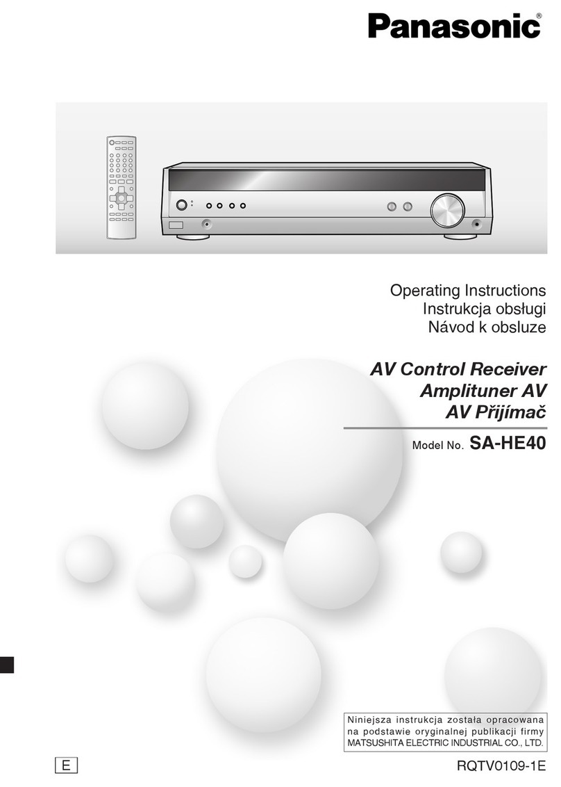
ORDERNO. MD0305192C2
AVControl Receiver
SA-XR15E / SA-XR15EB / SA-XR15EG
Colour
(S).......................Silver Type
(K).......................Black Type
SPECIFICATIONS
Specification
AMPLIFIER SECTION
Power output (at AC 230-240V)
DIN 1kHz (T.H.D. 1%) 2x40 W(6)
20 Hz-20 kHz continuouspower
output bothchannelsdriven 2x35 W(6)
Total harmonicdistortion
ratedpower at 20 Hz-20 kHz 0.9%(6)
Power output eachchannel driven
DIN 1kHz (T.H.D. 1%)
Front (L/R) 40 W(6)
Center 40 W(6)
Surround (L/R) 40 W(6)
10 %total harmonicdistortion at 1
kHz
Front (L/R) 50 W(6)
Center 50 W(6)
Surround (L/R) 50 W(6)
Loadimpedance
Front (L/R) 6-16
Center 6-16
Surround (L/R) 6-16
Frequencyresponse
DVD, TV, VCR, AUX 10 Hz-44 kHz, ±3 dB
Input sensitivityand impedance
1
DVD, TV, VCR, AUX 200 mV / 22 k
S/N at ratedpower (6 )
DVD, TV (Digital Input) 90 dB (IHF, A:96 dB)
Tonecontrols
BASS 50 Hz, +10 to-10 dB
TREBLE 20 kHz, +10 to-10 dB
Output voltage
VCR 200 mV
Channel balance (250 Hz-6.3kHz) ±1 dB
Channel separation 55 dB
Subwoofer frequencyresponse (-6dB) 7-200 Hz
Digital input
Optical 2
Coaxial 1
FM TUNER SECTION
Frequencyrange 87.50-108.00 MHz
Sensitivity
S/N 30 dB 1.5V / 75
S/N 26 dB 1.3V / 75
S/N 20 dB 1.2V / 75
IHFusablesensitivity(IHF’58) 1.5V / 75
IHF46 dB stereoquieting sensitivity 22 V / 75
Total harmonicdistortion
MONO 0.2%
STEREO 0.3%
S/N
MONO 60 dB
STEREO 58 dB
Frequencyresponse
20 Hz-15kHz +1dB, -2dB
Alternatechannel selectivity
±400 kHz 65 dB
Capture ratio 1.5dB
Imagerejection at 98 MHz 40 dB
IFrejection at 98 MHz 70 dB
Spuriousresponse rejection at 98 MHz 70 dB
AM suppression 50 dB
Stereoseparation
1kHz 40 dB
Carrier leak
19 kHz -30 dB
38 kHz -50 dB
Channel balance (250 Hz-6.3kHz) ±1.5dB
Limiting point 1.2V
Bandwidth
IFamplifier 180 kHz
FM demodulator 1000 kHz
Antennaterminal 75 (unbalanced)
2
AM TUNER SECTION
Frequencyrange 522-1611 kHz / (9kHz
steps)
530-1620 kHz / (10
kHz steps)
Sensitivity 20 V, 330 V/m
Selectivity(at 999 kHz) 55 dB
IFrejection (at 999 kHz) 50 dB
VIDEO SECTION
Output voltageat 1V input (unbalanced) 1±0.1Vp-p
Maximuminput voltage 1.5Vp-p
Input/output impedance 75
GENERAL
Power supply
ForE, EG AC 230 V, 50 Hz
ForEB AC 230-240 V, 50 Hz
Power consumption 65 W
Dimensions(W× H × D) 430 × 52 × 375 mm
Mass 3.5kg
Power consumption instandbymode: 2 W
Notes:
1.Specificationsare subject tochangewithout notice.
Mass and dimensionsare approximate.
2.Total harmonicdistortion ismeasuredbythedigital
spectrum/ analyzer.
2003 PANASONICAVCNetworks Singapore Pte. Ltd. All rights
reserved. Unauthorized copying and distribution isaviolation of
law.
1. SAFETY PRECAUTIONS
1.1. GENERALGUIDELINES
1. When servicing. observe the original lead dress. Ifashort circuit
isfound, replace all parts which have been overheated or
damaged bythe short circuit.
3
2. After servicing, see to itthat all the protective devices such as
insulation barriers, insulation papers shields are properly
installed.
3. After servicing, make the following leakage current checks to
prevent the customer from being exposed to shock hazards.
1.1.1. LEAKAGE CURRENTCOLD CHECK
1. Unplug the AC cord and connect ajumper between the two
prongs on the plug.
2. Measure the resistance value, with an ohmmeter, between the
jumpered AC plug and each exposed metalliccabinet part on the
equipment such as screwheads, connectors, control shafts, etc.
When the exposed metallicpart has areturn path to the chassis,
the reading shouldbe between 1M and 5.2 . / When the
exposed metal does not have areturn path to the chassis, the
reading must be . Fig. 1
1.1.2. LEAKAGE CURRENTHOTCHECK (See Figure1.)
1. Plug the AC cord directlyinto the AC outlet. Donot use an
isolation transformer for thischeck.
2. Connect a1.5k , 10 watts resistor, inparallel with a0.15 F
capacitors, between each exposed metallicpart on the set and a
good earth ground such as awater pipe, as showninFigure 1.
3. Use an AC voltmeter, with 1000 ohms/voltor more sensitivity, to
measure the potential across the resistor.
4. Check each exposed metallicpart, and measure the voltage at
each point.
5. Reverse the AC plug inthe AC outlet and repeat each of the above
measurements.
4
6. The potential at anypoint shouldnot exceed 0.75 volts RMS. A
leakage current tester (Simpson Model 229 or equivalent) maybe
used to make the hot checks, leakage current must not exceed 1/2
milliamp. Incase ameasurement isoutside of the limits specified,
there isapossibilityof ashock hazard, and the equipment should
be repaired and rechecked before itisreturned to the customer.
2. Handling the Lead Solder
2.1. About lead free solder (PbF)
Distinction of PbF P.C.B. :
P.C.B.s (manufactured) using leadfree solderwill have a PbF stampon the P.C.B.
Caution:
-Pb free solder has ahigher melting point that standard solder;
Typicallythe melting point is50 -70°F (30 -40°C)higher. / Please
use ahigh temperature soldering iron. Incase of the soldering
iron with temperature control, please set itto 700 ± 20°F (370 ±
10°C).
-Pb free solder will tend to splash when heated too high (about
1100°F/600°C).
-When soldering or unsoldering, please completelyremove all of
the solder on the pins or solder area, and be sure to heat the
soldering points with the Pb free solder until itmelts enough.
3. Before Repair and Adjustment
Disconnect AC power, discharge PowerSupplyCapacitors (C523, C524, C707, C717, C718)
through a 10 , 10 W resistortoground.
DO NOTSHORT-CIRCUITDIRECTLY (witha screwdriverblade, forinstance), as this may
destroysolidstate devices.
Afterrepairs are completed, restore powergraduallyusing a variac, toavoidovercurrent.
ForEB Current consumption at AC 230V-240V, 50Hz inNO SIGNALmode shouldbe 250~600
mA .
ForE, EG Current consumption at AC 230V, 50Hz inNO SIGNALmode shouldbe 250~600 mA .
4. About the Protection Circuitry
The protection circuitrymayhave operatedif eitherof the following conditions is noticed:
*Nosound is heardwhenthe poweris supplied.
*Sound stops during a performance.
The functions of this circuitryis toprevent circuitrydamage, forexample, the positive and
negative speakerconnection wires are “shorted”, orif speakersystems withanimpedance less
thanthe indicatedratedimpedance of this unit are used.
If this occurs, followthe procedure outlinedbelow:
1. Press the STANDBY /ONbutton, switch to STANDBYmode.
5
2. Determine the cause of the problem and correct it.
3. Press the STANDBY /ONbutton once again, supplythe power.
Note:
Whenthe protection circuitryfunctions, the unit will not operate unless the STANDBY /ON
button is first switchedSTANDBY and thenON again.
5. Accessories AC powersupplycord/ .....1 pc (EB)
AC powersupplycord/ .....1 pc (E, EG)
FM indoorantenna / .....1 pc
AM loop antenna / .....1 pc
6
Antenna plug adapter / .....1 pcs (EG)
Remote control / .....1 pc
6. Caution for AC Mains Lead
7
7. Operation Procedures
8. Disassembly and Main Component Replacement
Procedures and Operational Check
“ATTENTION SERVICER”
Some chassis components mayhave sharpedges.
Be careful whendisassembling and servicing.
8
-Thissection describes procedures for checking the operation of
the major printed circuitboards and replacing the main
components.
-For reassemblyafter operation checks or replacement, reverse the
respective procedures. Special reassemblyprocedures are
described onlywhen required.
Contents
-Checking for the MainPCB and DSP PCB
-Checking for the Input output PCB
-Checking for the Power SupplyPCB
8.1. Checking for the MainP.C.B. and DSP P.C.B.
Steps 1 and 2 : Remove all the screws.
Step3 : Remove the top cover.
Step4 : Remove the LeadCramper.
9
Step5 : Remove the screws.
Step6 : Release the claws of P.C.B. support and remove the DSP P.C.B.
-Check the DSP P.C.B. (Side B)as shownbelow.
Step7 : Remove the screwand DecorderAngle forchecking Digital AMP P.C.B.
8.2. Checking for the Input P.C.B
*Repeat step1 tostep4 for8.1.
10
Step1 : Remove the connector(CP500).
Step2 : Remove all the screws.
Step3 : Remove the rearpanel.
Step4 : Remove all the screws.
Step5 : Turnup the Input P.C.B.
-Check the Input P.C.B. as shownbelow.
8.3. Checking for the Power SupplyP.C.B.
11
*Repeat step1 tostep7 for8.1.
*Repeat step1 tostep3 for8.2.
Step1 : Remove the screwand Heat Barrier.
Step2 - 4 : Remove all the screws.
Step5 : Remove the flat-cable fromthe connector(CN951B).
12
Step6 : Remove all the screws.
Step7 : Remove all the connectors (CN951B, CN901 and CN902).
Step8 : Release the 2 claws and remove the front panel ass’y.
Step9 : Remove the volume knob.
Step10 : Remove the nut.
Step11 : Remove all the screws.
Step12 : Remove the front frame as arrowshownabove.
13
Step13 : Release the claws of the P.C.B. support.
Step14 : Release the connector(CN952) and remove the FL P.C.B.
Step15 : Remove all the screws and Light Guide Unit.
Step16 : Remove all the screws.
Step17 : Remove the Volume P.C.B. and LED P.C.B.
14
Step18 : Turnthe PowerSupplyP.C.B. as arrowshownabove.
-Check the Power SupplyP.C.B. as shownbelow.
Step19 : Connect back the connectors (CN952, CN902, CN901 and CN951B).
9. Self Diagnosis Display Function
This unit is equippedwiththe self diagnosis displayfunction, whichalarms faultyoperation
witherrorcode. Use this function during servicing.
9.1. AutomaticallyDisplayed Error Codes
Anerrorcode automaticallyappears on the display(LCD) whenfaultyoperation is detected.
RefertoFig. 9.1.
<Fig. 9.1>
15
9.2. DisplayDetails
Refertothe following table.
LCD display Symptom Cause and Remedy
OVERLOAD Speakershort, amplifierfailure Speakershort and failure in
poweramplifier, pre-amplifier
circuits. Check forfaulty
parts
and replace withnewparts if
necessary.
Humidityprotection activated
FANLOCK The fanstops suddenly. Failure infanorfancontrol
circuits. Check forfaulty
parts
and replace withnewparts if
necessary.
F70 Communication errorbetween
sub microprocessorand its
peripheral LSI
Failure sub-microprocessor
and its peripherals LSI.
Check
forfaultyparts and replace
with
newparts if necessary.
F76 Whenthe poweris turnedon,
the unit powerautomatically
turns off; the powercannot be
turnedon.
Failure inthe powercircuit
systemof the unit. This may
happenwhenthe direct
current
electricityis suppliedto
speaker
terminals. Check forthe
above
and replace withnewparts if
necessary.
9.3. Activating SelfDiagnosisFunction (Servicing Mode)
This mode canbe usedduring servicing.
1. Plug the AC adapter to the power source. Press and holddown
the INPUTSELECTORbutton and the PRESET button, and then
press the POWERbutton.
2. The message, DISPLAYappears on the displayfor three seconds,
and then disappears.
3. When the TUNING DOWNbutton ispressed, the current program
filing number (ex. "M45_***" for MA123_45) appears. The *** digit
16
indicates the ROMchecksum used for ROMcollection, and ifthe
unitisnot loaded with ROM, "NO"appears.
When the TUNING UPbutton ispressed, the sub micro computer
program filing number (ex. S90_***" for MA678_90) appears. The **
*digitindicates the ROMchecksum used for ROMcollection, and
ifthe unitisnot loaded with ROM, "NO"appears.
4. When the MEMORYbutton on the remote controller, the function
isswitched to "Input Inspection Mode", which output analog input
signalsat Lchannel of VCR analog input to all channels.
9.4. Returning to Normal Display
Press the POWER button on the unit toexit the function. The poweris turnedoff.
10. Type Illustration of IC's, Transistors and Diodes
11. Schematic Diagram
(All schematic diagrams maybe modifiedat anytime withthe development of the new
technology)
Note:
S941
:POWERswitch
S961
:FM MODEswitch
S962
:MEMORYswitch
S963
:PRESET switch
S964
:TUNEDOWNswitch
S965
:TUNEUPswitch
S966
:SELECTORswitch
S969
:RDS/BAND switch
-The voltage value and waveforms are the reference voltage of this
17
unitmeasured byDC electronicvoltmeter (high impedance) and
oscilloscope on the basisof chassis. Accordingly, there mayarise
some error involtage values and waveforms depending upon the
internal impedance of the tester or the measuring unit.
-Importance safetynotice :
Components identified bymark have special characteristics
important for safety. Furthermore, special parts which have
purposes of fire-retardant (resistors), high-qualitysound
(capacitors), low-noise (resistors), etc. are used. When replacing
anyof components, be sure to use onlymanufacturer's specified
parts showninthe parts list.
Caution !
IC, LSI and VLSI are sensitive tostatic electricity.
Secondarytrouble canbe preventedbytaking care during repair.
-Cover the parts boxes made of plastics with aluminium foil.
-Put aconductive mat on the work table.
-Ground the soldering iron.
-Donot touch the pins of IC, LSI or VLSI with fingers directly.
12. Printed Circuit Board Diagram
13. Block Diagram
14. Wiring Connection Diagram
15. Terminal Function of ICs
15.1. IC801 (C2BBGF000440): System Control (Micro P)
18
Pin
NO. Terminal
Name I/O Function
1 LED_CK O LED DriverControl : Clock
2LED_DT I LED DriverControl : Data
3LED_ST I/O LED DriverControl : Strobe
4E_DT O EEPROM Control : Data
5 E_CK O EEPROM Control : Clock
6 E_CS O EEPROM Control : Chip
Select
7 REQS I/O Communication toSub up :
Request fromSub up
8REQM I/O Communication toSub up :
Request fromMainup
9M_CK O Communication toMainup :
Clock
10 M2S_DT O Communication toMainup :
Serial Output
11 S2M_DT I Communication toMainup :
Serial Input
12 F_BUSY I/O To rewrite up ROM : BUSY
13 F_CK O To rewrite up ROM : CLOCK
14 V_A I/O VideoSelectorControl : A
15 F_DA I/O To rewrite uP ROM : DATA
16 V_B I/O VideoSelectorControl : B
17 REMOTE I Remote Control Signal Input
18 CNVSS /
(VPP) - 12V supplytorewrite Flash
ROM
19 RESET - Reset Input
20 AC__SYNC - PowerFaillure Detection
21 FAN_LOCK - FAN LOCK Detection
22 XIN - 10MHz Connect toOscillator
23 XOUT - 10MHz Connect toOscillator
24 VSS - Connect toGND
25 MT_ALL O MUTE forall channel
26 MT_C/SR O MUTE forC/SURR
27 MT_SUB O MUTE forSUBWFR
28 MT_HP O MUTE forHeadphones
29 OSD_CK O OSD Control : Clock
30 OSD_DT I OSD Control : Data
31 OSD_ST I/O OSD Control : Strobe
32 DC_DET I DC Short Detection
33 INI_OUT O Output forInitialize Setting
34 POWER_RLY -PowerRelayControl (H ;
ON)
19
ON)
Pin
NO. Terminal
Name I/O Function
35 M_RESET O RESETsignal forsub up
36 FAN_CTRL O Cooling FanControl Output
37 HP_SW I Headphone Detection
38 MT_2ND O MUTE for2nd Audio
39 RDS_CK O RDS IC Control : Clock
40 RDS_DI I RDS IC Control : Data
41 INIT_IN1 I Initialize Setting Input 1
42 INIT_IN2 I Initialize Setting Input 2
43 TUN_SD I SD Input forTuner
44 TUN_DI/ST I IFdata/Sterodetect input
fortuner
45 TUN_CE O CE Output fortuner
46 SEL/TN/ /
DA_CK O Input Selector, Tunerand D/
A Control : Clock
47 SEL/TN/ /
DA_DT O Input Selector, Tunerand D/
A Control : Data
48 SEL_ST O Input SelectorControl :
Strobe
49 F_OE O To rewrite up ROM :
ENABLE
50 FL_CK O FL DriverControl : Clock
51 FL_DT I FL DriverControl : Data
52 FL_ST I/O FL DriverControl : Strobe
53 AMP_RESET OTAS5036 Hardware Reset
54 DBL_SPD I/O Sample Rate Double Speed
Control tothe modulatorIC
55 A/D_ATT I/O A/D attenuatorControl
56 D/A_ST I/O D/A Control : Strobe
57 VCC - +5V powersupply
58 VREF - VCC Connected
59 AVSS - GND Connected
60 THRM_DET I Thermal Warning Detection
61 SHORT_DET I Output Short Detection
62 SPKR_IN O SpeakerOutput Voltage
Input forFAN Control
63 KEY2 I Keyinput 2
64 KEY1 I Keyinput 1
16. Parts Location and Replacement Parts List
Notes:
-Important safetynotice:
20

This manual suits for next models

2

Other Panasonic Stereo Receiver manuals
Panasonic SA-XR55E User manual

Panasonic

Panasonic SA-XR55E User manual
Panasonic SA-DX940 User manual

Panasonic

Panasonic SA-DX940 User manual

Panasonic SADA15 - RECEIVER User manual

Panasonic

Panasonic SADA15 - RECEIVER User manual

Panasonic SAEX320 - RECEIVER User manual

Panasonic

Panasonic SAEX320 - RECEIVER User manual

Panasonic SAHE200 - RECEIVER User manual

Panasonic

Panasonic SAHE200 - RECEIVER User manual

Panasonic SAHT210 - RECEIVER User manual

Panasonic

Panasonic SAHT210 - RECEIVER User manual

Panasonic RF-SW150 User manual

Panasonic

Panasonic RF-SW150 User manual

Panasonic SA-XR30 User manual

Panasonic

Panasonic SA-XR30 User manual

Panasonic SA-XR10E User manual

Panasonic

Panasonic SA-XR10E User manual

Panasonic RF-TJ10 User manual

Panasonic

Panasonic RF-TJ10 User manual

Panasonic RF-U700 User manual

Panasonic

Panasonic RF-U700 User manual

Panasonic RF-SW150 User manual

Panasonic

Panasonic RF-SW150 User manual

Panasonic SAHT210 - RECEIVER User manual

Panasonic

Panasonic SAHT210 - RECEIVER User manual

Panasonic SA-HE40 User manual

Panasonic

Panasonic SA-HE40 User manual

Panasonic SAHE100 - RECEIVER User manual

Panasonic

Panasonic SAHE100 - RECEIVER User manual

Panasonic SAHE100 - RECEIVER User manual

Panasonic

Panasonic SAHE100 - RECEIVER User manual

Panasonic SC-HT260 Operating User manual

Panasonic

Panasonic SC-HT260 Operating User manual

Panasonic VIERA SA-BX500EB User manual

Panasonic

Panasonic VIERA SA-BX500EB User manual

Panasonic SAAX730 - RECEIVER User manual

Panasonic

Panasonic SAAX730 - RECEIVER User manual

Panasonic SA-XR10E User manual

Panasonic

Panasonic SA-XR10E User manual

Panasonic HDMI SA-XR70E User manual

Panasonic

Panasonic HDMI SA-XR70E User manual

Panasonic SG-250R/25Q User manual

Panasonic

Panasonic SG-250R/25Q User manual

Panasonic SAHE200 - RECEIVER User manual

Panasonic

Panasonic SAHE200 - RECEIVER User manual

Panasonic SAHT220 - RECEIVER User manual
Panasonic

Panasonic SAHT220 - RECEIVER User manual

Popular Stereo Receiver manuals by other brands

Sony STR-DE575 - Fm Stereo/fm-am Receiver Service manual

Sony

Sony STR-DE575 - Fm Stereo/fm-am Receiver Service manual

Denon AVR-E200 owner's manual

Denon

Denon AVR-E200 owner's manual

Denon AVR-3808CI Addendum sheet

Denon

Denon AVR-3808CI Addendum sheet

Pioneer AVH-W4500NEX Operation manual

Pioneer

Pioneer AVH-W4500NEX Operation manual

Sony STR-DE597P Service manual

Sony

Sony STR-DE597P Service manual

Denon AVR-S750H owner's manual

Denon

Denon AVR-S750H owner's manual

Sony STR-DA1000ES Easy setup guide

Sony

Sony STR-DA1000ES Easy setup guide

Aiwa NSX-S222 Service manual

Aiwa

Aiwa NSX-S222 Service manual

Technics SA-GX350 Service manual

Technics

Technics SA-GX350 Service manual

Denon AVR-1708 Dimensions

Denon

Denon AVR-1708 Dimensions

Alpine iLX-207 owner's manual

Alpine

Alpine iLX-207 owner's manual

Denon AVR-4308CI Specification sheet

Denon

Denon AVR-4308CI Specification sheet

Pioneer SX-626 KCW Wiring diagram

Pioneer

Pioneer SX-626 KCW Wiring diagram

Kenwood KRF-X9992D Connection and setup guide

Kenwood

Kenwood KRF-X9992D Connection and setup guide

Sony STR-SL7 - Fm Stereo/fm-am Receiver operating instructions

Sony

Sony STR-SL7 - Fm Stereo/fm-am Receiver operating instructions

Sony STR-K870P Service manual

Sony

Sony STR-K870P Service manual

Pyle PLCD43BTM user guide

Pyle

Pyle PLCD43BTM user guide

Emerson NR40 owner's manual

Emerson

Emerson NR40 owner's manual

manuals.online logo
manuals.online logoBrands
  • About & Mission
  • Contact us
  • Privacy Policy
  • Terms and Conditions

Copyright 2025 Manuals.Online. All Rights Reserved.