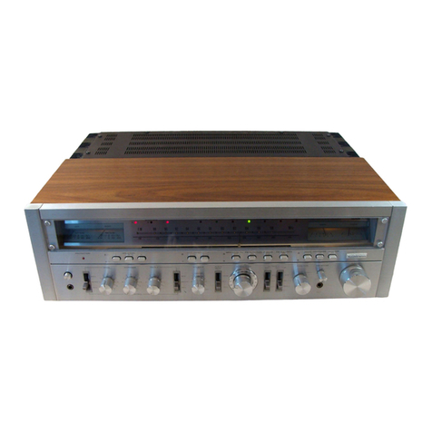
Hitachi SR-904 User manual

pr
z
:
:
i
d
.
a
t
:
Boot
:
:
;
e
:
i
]
eee
;
i
Congratulations!
STEREO
RECEIVER
INSTRUCTION
MANUAL
HITACH!
Hi-Fi
products
are
the
proud
result
of
HITACHI
engineering
research
and
development
and
over
50
years
of
experience
in
electronics.
Laboratories
and
major
testing
facilities
are
maintained
in
Tokyoand
Toyokawa,
Japan.
In
choosing
this
fine
HITACHI
Hi-Fi
product
you
have
demonstrated
an
acute
awareness
of
“getting
the
most
for
your
money’,
With
HITACHI
products
this
is
not
an
idle
boast.
KEY
TO
ILLUSTRATIONS
POWER
switch
PHONES
jack
PROTECTION
indicator
SPEAKERS
switches
(A,B)
BASS
control
MIDRANGE
control
TREBLE
control
LOW
FILTER
switch
HIGH
FILTER
switch
VOLUME
contro!
BALANCE
contro}
TAPE
COPY
switch
TAPE
MONITOR
switch
FUNCTION
switch
MODE
switch
LOUDNESS
switch
ADAPTOR
switch
Tuning
knob
TUNING
meter
SIGNAL
meter
Dial
pointer
®
@
@
4)
©
©)
@
g
a)
(2)
13)
(5)
@
20)
Qt)
SAFEGUARD
Electrical
energy
can
perform
many
useful
functions.
This
unit
has
been
engineered
and
manufactured
to
Program
source
indicators
FM
AUTO
LOCK
indicator
FM
STEREO
indicator
Q5)
Power
meters
PHONO
input
terminals
Q7)
AUX
input
terminals
TAPE-1
PLAY
terminals
Q3)
TAPE-1
REC
OUT
terminals
TAPE-1
DIN
REC/PLAY
socket
6)
TAPE-2
PLAY
terminals
62)
TAPE-2
REC
OUT
terminals
83)
ADAPTOR
IN
terminals
ADAPTOR
OUT
terminals
65)
SPEAKERS
terminals
AC
line
cord
67)
FUSE
AM
bar
antenna
6)
AM
ANTENNA
terminal
FM
ANTENNA
terminals
FM
ANTENNA
socket
(75
ohms)
42
Ground
terminal
(GND)
22)
23)
24)
assure
your
personal
safety.
Improper
use
can
result
in
potential
electrical
shock
or
fire
hazards,
In
order
not
to
defeat
the
safeguards,
observe
the
following
instructions
for
its
installation,
use
and
servicing.
WARNING:
TO
PREVENT
FIRE
OR
SHOCK
HAZARD,
DO
NOT
EXPOSE
THIS
APPLIANCE
TO
RAIN
OR
MOISTURE.

INSTALL
ATION
Please
choose
a
place
that
satisfies
the
following
conditions
when
stalin
the
SR-904.
1.
A
place
free
from
direct
sunlight
and
heat
from
a
stove,
etc.
2.
Since
the
SR-904
incorporates
a
large
power
Output
amplifier,
choose
a
well-
ventilated:
moisture-free
place.
3.
Install
on
a
stable
and
vibration-free
surface.
IMPORTANT
FOR
U.K::
WARNING:
This
apparatus
must
be
earthed.
The
wires
in
this
mains
lead
are
coloured
In
accordance
with
the
following
code:
Green
and
Yellow
>
EARTH
Blue
>
NEUTRAL
Brown
>
LIVE
As
the
colours
of
the
wires
in
the
mains
lead
of
this
apparatus
may
not
correspond
with
the
coloured
markings
identifying
the
terminals
in
your
plug
proceed
as
follows.
The
wire
which
is
coloured
GREEN
and
YELLOW
must
be
connected
to
the
terminal
in
the
plug
which
is
marked
by
the
letter
E
or
by
the
safety
earth
symbol
sor
coloured
GREEN
or
GREEN
and
YELLOW.
The
wire
which
is
coloured
BLUE
must
be
connected
to
the
terminal
which
is
marked
with
the
letter
N
or
coloured
BLACK.
The
wire
which
is
coloured
BROWN
must
be
connected
to
the
terminal
which
is
marked
with
the
letter
L
or
coloured
RED.
IMPORTANT
NOTICES
(1)
When
measuring
the
power
output
or
listening
to
program
sources
with
a
4
ohms
load
impedance,
do
not
drive
the
Model
SR-904
at
full
power
for
a
long
period
of
time.
(2)
When
using
the
model!
with
a
continuous
output
of
over
150
watts,
the
protection
indicator
will
tight
up
and
the
sound
will
sometimes
be
interrupted.
This
does
not
indicate
a
breakdown,
In
such
cases,
turn
off
the
power,
turn
down
the
volume
level
and
then
wait
about
30
seconds
before
switching
the
power
back
on
again.
NOTE:
Power
meter
25
indication
When
the
impedance
of
speakers
is
8
ohms,
the
scales
of
the
meters
express
the
power
output
in
Watts.
When
the
impedance
of
the
speakers
is
only
4
ohms,
the
actual
output
is
double
the
value
indicated
on
the
meters.
For
example,
if
the
pointers
point
to
50
watts
on
the
scales,
then
the
actual
output
is
100
watts.
(3)
The
Model
SR-904
has
two
types
of
electronic
protection
circuits;
a
shut-down
circuit
and
current
limiter
circuit.
lf
the
shut-down
circuit
is
actuated,
the
output
of
the
amplifier
is
cut
off.
When
only
the
current
limiter
circuit
is
actuated,
the
operation
of
the
power
amplifier
is
not
shut
down,
(4)
A
tape
deck
being
used
may
be
susceptible
to
induction
from
the
receiver,
although
this
depends
on
the
type
of
tape
deck,
and
there
may
be
a
hum
sound.
In
such
cases,
install
the
tape
deck
in
a
location
where
it
will
not
be
susceptible
to
the
induction.
(For
instance,
plete
the
tape-deck
on
the
right
of
the
receiver
when
viewed
from
the
front).
Do
not
place
the
tape
deck
on
top
nor
on
the
left
of
the
receiver
since
this
will
impair
the
receiver's
perfor-
mance,
FEATURES
Tuner
Section
1.
Dual
Gate
MOS
FET
for
High
Quality
FM
Tuner
The
dual
gate
MOS
FET
in
the
front-end
and
the
4-gang
variable
capacitor
offer
excellent
FM
sensitivity
(1.6
uV),
intermodulation
characteristics,
a
high
S/N
ratio
and
spurious
rejection.
2.
Auto-Lock
Circuit
To
stabilize
tuning,
an
Auto-Lock
circuit
is
provided.
This
circuit
engages
immediately
when
you
release
the
tuning
knob
after
precise
tuning.
Just
by
touching
the
tuning
knob,
you
can
disengage
the
Auto-Lock
circuit
(the
Auto-Lock
indicator
goes
off}
for
fine
tuning.
Releasing
the
tuning
knob
re-engages
the
Auto
Lock
circuit
which
automatically
stabilizes
the
tuning
Circuit
and
locks
onto
the
station
selected
for
a
high
S/N
ratio
and
low
distortion.
E~2

.
High-Selectivity
and
Low-Distortion
1F
Amplifier
Using
ICs,
and
3
Ceramic
Filters
A
4-stage
differential
amplifier
is
employed.
The
extensive
use
of
|Cs,
together
with
3
cermic
filter
elements
having
good
phase
characteristics
in
the
FM-IF
amplitier
greatly
improves
the
limiter
and
selectivity
character-
istics.
.
Quadrature
Detection
Quadrature
detection
with
the
extensive
use
of
ICs
yields
a
wide
band
coverage
and
low
distortion.
.
Phase-Locked
Loop
IC
for
FM/MPX
Circuit
A
PLL-IC,
which
was
developed
by
HITACHI,
is
used
for
the
FM/MPX
circuit to
produce
a
high
separation
and
low
distortion,
Also,
high
reliability
is
achieved
with
respect
to
temperature
and
aging.
.
Ceramic
Filter,
iCs
tn
AM
Tuner
A
ceramic
filter
is
employed
in
the
AM
tuner
to
obtain
high
selectivity
and
AGC
characteristics.
The
extensive
_use
of
ICs
enables
stable
reception
to
be
achieved.
.
Two
Large
Easy-to-read
meters
and
a
Large-sized
Fiy-wheel
Tuning
Knob
Two
easy-to-read
meters
are
used
for
signal
tuning.
The
dial
mechanism
employs
a
large-sized
flywheel
with
a
high
moment
of
inertia
for
easy
operation.
Audio
Section
1.
Newly
Developed
High-Efficiency
High
Power
Audio
Amplifier
(Dynaharmony
Amplifier)
This
amplifier
delivers
a
higher
dynamic
power
output
(150
watts
per
channel,
8
ohms)
without
distortion
than
conventional
Class
B
amplifiers.
|
The
relative
low
power
consumption
of
Dynaharmony
operation
minimizes
the
heat
sink
of
power
transistors,
and
slims
down
the
weight
and
size
of
the
whole
amplifier.
This
amplifier
has
2
pairs
of
DC
power
supplies.
Under
this
method,
Dynaharmony
operation
can
deliver
dynamic
power
which
is
more
than
twice
the
value
of
the
maximum
rated
power
output
or
more.
.
Electronic
Protection
Circuits
HITACHI’s
original,
highly
reliable
electronic
protection
circuits
protect
the
speakers
and
power
transistors.
When
a
fault
occurs,
the
circuit
is
switched
off
and
this
is
then
displayed
on
the
front
panel
by
the
light-
emitting
diode.
.
Separate
Power
Meters
(L
and
R
channels)
To
see
the
actual
power
output
while
you
are
listening,
two
new
attractive
power
meters
are
provided.
.
Tape
Dubbing
Tape
dubbing
can
be
done
either
from
TAPE-1
to
TAPE-2
or
vice
versa.
|n
addition,
a
source
monitor
circuit,
with
which
tape
dubbing
is
possible
while
listening
to
an
FM
broadcast
or
a
record,
is
provided.
.
Midrange
Tone
Control
This
amplifier
has
not
only
BASS
and
TREBLE
tone
controls
but
also
a
MIDRANGE
tone
control.
By
setting
these
three
controls,
you
can
choose
the
preferred
frequency
characteristics
of
the
amplifier.
The
controls
all
have
11
click
stops.
This
feature
offers
good
feel
which
makes
for
easier
setting
and
resetting.
.
Low
Filter
and
High
Filter
The
{ow
filter
cuts
out
the
low
frequency
noise
such
as
the
turntable
rumble
and
the
high
filter
cuts
out
high
frequency
noise
such
as
the
scratch
noise
of
records
while
listening
to
FM
broadcasts.
.
Two
Speaker
Systems
Two
different
types
of
speaker
systems
can
be
connected
to
the
unit
and
they
can
be
selected
simply
by
flipping
a
switch.
CONNECTING
1.
It
CONNECTION
OF
SPEAKERS
is
possible
to
connect
two
pairs
of
speaker
systems
to
the
SR-904,
You
can
use
the
two
pairs
of
speakers
simul-
taneously
and
enjoy
music
in
different
rooms
using
the
SPEAKERS
switches
@.
NOTES:
pedance
of
the
speakers
is
only
2
ohms
and
so
(1)
As
illustrated
in
the
figure,
on
the
cover
page,
the
PROTECTION
indicator
@
will
come
on.
the
right
side
terminals
are
for
the
left
chan-
Avoid
using
this
arrangement.
Be
sure
to
nel,
and
left
side
channel
are
for
right
channel.
connect
speakers
of
more
than
8
ohms
when
The
red
terminals.
are
positive
(+),
and
the
two
sets
of
speakers
are
to
be
operated
black
terminals
are
negative
(-).
Make
sure
simultaneously.
the
polarities
of
the
terminals
in
this
receiver
(3)
Turn
the
SPEAKERS
switches
@)
off
when
correspond
to
those
of
the
speakers
terminals
only
headphones
are
being
used.
85).
(2)
When
4-ohm
speakers
are
connected
to
both
A
and
B,
and
the
SPEAKERS
switches
A
and
B
@
are
both
depressed,
the
combined
im-
of
the
speakers
Is
only
2
ohms
and
so
the

2.
CONNECTION
OF
TURNTABLE
Connect
the
turntable
as
shown
in
the
figure
on
the
cover
page.
It
is
different
depending
on
the
kind
of
cartridge
used.
(1)
Moving
Magnet
Cartridges
Connect
the
output
leads
of
the
turntable
to
the
PHONO
input
terminals
@6
.
(2)
Moving
Coil
Cartridges
Connect
to
the
PHONO
input
terminals
@6)
via
a
matching
transformer
or
pre-ampli-
fier.
3.
CONNECTION
OF
TAPE
DECKS
(3)
Ceramic
or
Crystal
Cartridges
Connect
to
the
AUX
input
terminals
@
.
NOTE:
Be
sure
to
connect
a
grounding
wire
from
the
turn-
table
to
the
ground
terminal
42
of
the
SR-904.
Both
pin-jack
connections
and
DIN
record/playback
single
cord
connection
(TAPE-1)
are
available,
Further,
-
since
two
sets
of
record
and
playback
terminalis
are
provided,
two
tape
deck
connections
are
available
at
the
same
time,
and
dubbing
or
duplicate
recordings
from
one
tape
deck
to
the
other
can
be
done,
(1)
Connection
with
DIN
record/playback
connector
(TAPE-1
only)
Insert
a
DIN
record/playback
connector
into
the
TPAE-1
DIN
REC/PLAY
socket
60.
See
the
figure
on
the
cover
page.
(2)
Connections
with
pin-plugs
(TAPE-1,
2)
Connect
the
record
terminals
(LINE
IN)
of
the
tape
deck
to
the
TAPE-1
REC
OUT
terminals
@9
and
the
output
terminals
(LINE
4.
USE
OF
THE
AUX
INPUT
TERMINALS
@
OUT)
of
the
tape
deck
to
the
TAPE-1
PLAY
terminals
@8
of
the
SR-904.
You
can
con-
nect
another
tape
deck
in
the
same
way
men-
tioned
above.
See
the
figure
on
the
cover
page.
NOTE:
If
the
TAPE-1
DIN
REC/PLAY
socket
80
is
used
for
recording
and
playing
back,
it
is
not
necessary
to
use
pin-jacks,
and
vice
versa.
These
terminals
are
a
set
of
spare
input
jacks.
They
can
be
connected
to
cartridge
tape
players,
television
sound
multiplex
tuners,
or
other
forms
of
signal
output.
The
upper
of
the
two
terminals
is
the
L
(left)
channel,
and
the
lower
is
the
R
(right)
channel.
5.
USE
OF
THE
ADAPTOR
TERMINALS
These
terminals
63,
64
are
a
set
of
adaptor
input-output
jacks.
They
can
be
connected
to
a
tape
deck
and
Dolby
adaptor.
Connect
the
input
terminals
(LINE
IN)
of
the
adaptor
to
the
ADAPTOR
OUT
terminals
64
and
the
output
terminals
(LINE
OUT)
of
the
adaptor
to
the
ADAPTOR
IN
terminals
63
of
the
SR-904.
RECEIVING
BROADCASTS
1.
RECEIVING
FM
BROADCASTS
(1)
Set
the
FUNCTION
switch
@4
to
FM.
When
receiving
FM
_
broadcasts,
unpleasant
inter-
station
noise
may
be
heard
when
tuning;
this
may
damage
the
speakers.
This
inter-station
noise
can
be
cut
by
the
following
procedure:
FUNCTION
switch
set
to
FM
MUTE/
AUTO
LOCK.
(2)
When
on
station
by
turning
the
Tuning
knob
(®,
the
SIGNAL
meter
@0
should
make
its
biggest
deviation
to
the
right
and
the
TUNING
meter
pointer
should
be
central
for
precise
tuning.
See
Fig.
1.
0
1
2
8
43S
ee
Cn
ay
ae
SIGNAL
METER
TUNING
METER
(for
FM
reception
only)
Fig:
1
(3)
Set
the
MODE
switch
@
to
STEREO
(2).
When
you
are
receiving
a
stereo
broadcast,
the
FM
STEREO
indicator
@4
will
illumi-
nate.
(4)
Adjust
the
balance
of
left/right
sound
with
the
BALANCE
control
@.
CAUTION:
If
the
input
signal
from
the
antenna
is
weak
(as
In
an
area
where
the
signal
strength
is
low),
and
if
the
FUNCTION
switch
is
set
at
FM
MUTE/
AUTO
LOCK,
the
broadcast
may
not
be
picked
up.
In
this
case,
set
the
FUNCTION
switch
to
FM.
*
FM
ANTENNA
CONNECTION
Accessory
T-type
FM
Antenna
lf
the
broadcasting
station
is
near
or
the
radio
field
strength
is
high,
this
antenna
is
sufficient.
Connect
the
lead
of
the
antenna
to
the
antenna
terminal
on
the
rear
of
the
receiver,
expand
the
antenna
into
a
“T’’-shape,
find
the
point
of
highest
sensitivity
and
fix
the
antenna
there.
Outdoor
FM
Antenna
When
using
this
tuner
far
from
the
broadcasting

station
or
behind
a
ferroconcrete
building
where
the
radio
field
strength
is
low,
install
an
outdoors
FM
antenna.
The
height
and
direction
of
the
out-
door
antenna
should
be
adjusted
for
optimum
reception.
When
the
distance
between
the
antenna
and
this
tuner
is
over
30
meters
(around
100
feet),
or
in
areas
subject
to
heavy
traffic
or
close
to
a
high-
tension
power
line,
noise
may
disturb
listening
even
when
the
FM
exclusive
antenna
is
sued.
However,
since
the
coaxial
cabJe
is
a
75
ohm
unbalanced”’
type,
install
a
matching
transformer
between
the
antenna
and
the
coaxial
cable
to
prevent
wave
loss.
When
this
conversion
trans-
former
is
incorporated
tn
the
antenna,
a
normal
75
ohm
coaxial
cable
can
be
used,
2.
RECEIVING
AM
BROADCASTS
(1)
Set
the
FUNCTION
switch
to
AM,
(2)
The
MODE
switch
(5
may
be
either
in
the
MONO
or
STEREO
position.
|
(3)
Find
the
desired
station
with
the
Tuning
knob
(48.
In
this
case,
the
point
where
the
pointer
of
the
SIGNAL
meter
@
shows
maximum
deviation
is
the
correct
tuning
point.
Outdoor
AM
Antenna
When
using
this
set
far
from
the
broadcasting
sta-
tion
or
at
a
place
where
the
radio
reception
is
adversely
affected
by
ferroconcrete
buildings
or
some
other
structure,
instal]
an
outdoor
antenna.
Connect
viny!
wire
to
the
AM
ANTENNA
ter-
minal
89
on
the
rear
of
this
set,
and
install
the
antenna
a
short
distance
from
the
building.
Fix
the
antenna
where
the
best
radio
reception
can
be
obtained.
!t
Is
desirable
for
safety’s
sake
to
equip
the
outdoor
antenna
with
an
arrester
switch.
3.
USING
THE
ADAPTOR
TERMINALS
Dolby
Recording
(1)
As
shown
in
Fig.
2
connect
the
ADAPTOR
OUT
terminals
@4
to
the
tape
deck
recording
input
terminals
(LINE
INPUT),
(2)
Select
the
program
source
of
your
choice
with
the
FUNCTION
switch
@.
NOTE:
If
you
wish
to
monitor
the
sound
being
recorded
with
the
Dolby
NR
adaptor,
turn
the
ADAPTOR
switch
()
ON.
Dolby
Playback
(1)
Connect
the
tape
deck
playback
output
termi-
nals
(LINE
OUTPUT)
to
the
ADAPTOR
IN
terminals
63).
(2)
Turn
the
ADAPTOR
switch
(7?
ON,
and
play-
back
your
Dolby
system
recordings.
NOTE:
For
detailed
instructions
on
connections
etc.,
please
see
the
instruction
manual
provided
with
your
as
Anica
te
NR
adaptor.
ADAPTOR
:
*
SIGNAL
SIGNAL
4
OFF
:
|
ADAPTOR
SWITCH
Fig.
3,
|
Fig.
2]
E—5
4.
OTHER
ADAPTORS
CURRENTLY
AVAILABLE
The
provision
of
these
additional
and
convenient
|
adaptor
terminals
to
the
normal
tape
REC
OUT/
PLAY
terminals,
enables
other
sophisticated
adap-
tor
units
(e.g.
a
graphic
equalizer,
dynamic
proces-
sor)
to
be
connected
without
impairing
the
full
tape
monitoring
and
duplicating
facility.
When
using
an
adaptor,
the
program
source
can
be
taken
from
the
FUNCTION
switch
(4
or
the
tape
deck
Output
terminals.
Fig.
3
illustrates
an
Adaptor
connected
to
the
ADAPTOR
terminals.
5.
USING
TAPE
DECKS
Playback
(1)
According
to
the
TAPE
PLAY
(1,
2)
@,
@1
or
ADAPTOR
IN
terminals
63
to
which
the
tape
deck
Is
connected,
the
TAPE
MONI-
TOR
switch
43
should
be
set
to
TAPE-1
or
TAPE-2,
or
the
ADAPTOR
switch
47
should
be
set
to
ON
(2)
(see
Fig.
4).
(2)
Operate
the
tape
deck
controls
for
playback.
(3)
Adjust
the
VOLUME
40,
BASS
©,
MID-
RANGE
©
and
TREBLE
@
controls
for
the
listening
level
and
tone
quality
of
vou
pre-
ference.
NOTE:
Setting
the
TAPE
MONITOR
switch
(3 to
TAPE-1
or
TAPE-2
enables
tape
playback
whatever
the
setting
of
the
FUNCTION
switch
@,
pais
ae
DECK
1
ta
won:
i
:
TAPE
DECK
2
TAPE
DECK
3
SONA
on
d
SIGNAL
;
e
@
OFF
H
4
souRcE™
~
ADAPTOR
SWITCH
|
1p2¥
t
TAPE
COPY
SWITCH
TAPE
MONITOR
SWITCH
|
Fig.
4
Recording
As
shown
in
Fig.
5,
the
receiver's
TAPE
REC
OUT
(1,
2)
@,
62
and
ADAPTOR
OUT
terminals
64
carry
a
certain
fixed
level
output
from
the
source
selected
by
the
FUNCTION
switch
44,
which
once
the
tape
deck
is
connected
to
the
ap-
propriate
jacks,
enables
the
selected
source
to
be
recorded.
The
operation
is
as
follows:
1.
Set
the
FUNCTION
switch
@
for
the
source
to
be
recorded.
2.
Play
the
selected
program
source.
3.
Adjust
the
recording
level
by
means
of
the
controls
on
the
tape
ciel
and
commence
recording.
NOTE:
The
receiver’s
VOLUME
4),
BASS
®,
MIDRANGE
®
and
TREBLE
@
controls
have
no
effect
on
the
recorded
sound
during
recording.
in
wa
a
Al

TAPE
DECK
1
TAPE
DECK
2
TAPE
DECK
3
i)
=
=,
as
leven
IBIS
i
aererry)
Pires
te:
LOPE
HITIOO
+
SIGNAL
U
'
SOURCE™
‘
|
127
.
‘
TAPE
COPY
SWITCH
TAPE
MONITOR
SWITCH
|
Tape
Monitor
|
While
a
recording
is
being
made
on
a
three-head
deck,
the
recorded
sound
can
be
monitored
through
the
speaker
systems
if
the
TAPE
MONI-
TOR
switch
43
is
turned
to
TAPE-1
or
TAPE-2,
In
this
case
both
recording
and
playback
connec-
tions
must
be
made.
DUBBING
(TAPE
COPY)
By
using
two
tape
decks,
a
recording
of,
say,
a
complete
FM
broadcast
can
be
made,
and
then
those
items
which
you
want
for
your
permanent
“tape
library’’
can
be
selected
and
re-recorded
onto
another
tape.
(1)
Connect
the
two
tape
decks
as
shown
in
Fig.
6.
(2)
Set
the
TAPE
COPY
switch
@2
to
1
>
2
or
2>
1
position.
CAUTIONS
Ad
4
Lar.
a
+O:
ap
SIGNAL
(3)
Select
one
of
the
tape
decks
(7
or
2)
to
play-
back
the
pre-recorded
tape,
and
use
the
other
tape
deck
to
make
the
copy
recording.
When
recording
with
tape
deck
1,
the
TAPE
MONITOR
switch
43
should
be
set
to
TAPE-1
to
monitor
the
sound
being
recorded.
And
when
recording
with
deck
2,
the
TAPE
MONITOR
switch
@
should
be
set
to
TAPE-2
for
monitoring
(refer
again
to
Fig.
6).
Set
the
TAPE
MONITOR
switch
43
to
SOURCE.
Tape
dubbing
is
possible
while
listening
to
the
source
sound
of
your
pre-
(4)
ference.
TAPE
DECK
1
TAPE
DECK
2
TAPE
DECK
3
———
Use
ato
G
all
SIGNAL
ON
(
*
es
-
'
SIGNAL
OFF
ADAPTOR
SWITCH
1p2¥
>
I
’
TAPE
COPY
SWITCH
TAPE
MONITOR
SWITCH
|
Fig.
6
1.
ON
THE
CONNECTION
OF
TURNTABLE
AND
TAPE
DECK
Be
sure-to
use
a
thick,
shielded
cable
with
a
low
stray
capacitance
for
this
connection.
If
a
parallel
vinyl
cord
or
a
thin
shielded
cable
is
used,
inductive
hum
may
be
produced
and
the
high
frequency
characteristics
will
deterio-
rate
considerably.
Therefore,
it is
recommended
that
you
use
as
thick
and
short
a
cable
as
possible.
2.
PROTECTION
CIRCUIT
Set
the
POWER
switch
to
ON,
the
sound
is
heard
within
3—6
sec.,
and
the
protection
indicator
lamp
goes
off.
If
the
sound
is
not
heard
after
3—6
sec.
or
the
protection
circuit
is
actuated
immediately,
turn
the
POWER
switch
to
OFF,
and
check
whether
the
speakers
are
properly
connected
and
whether
the
speaker
terminal
or
speaker
leads
are
short-circuited.
Then
eliminate
the
cause
of
trouble,
set
the
POWER
switch
to
ON
again
after
waiting
for
30
sec.
with
the
POWER
switch
at
OFF.
If
the
set
still
does
not
work,
contact
the
dealer
from
whom
you
purchased
this
unit
or
your
nearest
service
station.
3.
PROTECTIVE
FUSE
If
the
protective
fuse
blows
during
the
operation
of
this
unit,
unplug
the
power
cord
and
replace
the
fuse
(T3.15
A/
250
V).
In
this
case,
however,
the
new
fuse
is
not
a
fast-blowing
fuse.
Pay
attention
to
this
point.
Don't
use
thin
wires
temporarily.
If
the
replaced
fuse
blows
again,
something
may
be
wrong
with
the
power
supply
circuitry.
In
this
case
contact
the
dealer
from
whom
you
purchased
this
unit
or
your
nearest
service
station.
4.
CAPACITY
OF
SPEAKER
AND
IMPEDANCE
The
max.
input
capacity
is
indicated
on
the
speaker
systems:
use
suitable
speaker
systems.
Although
the
speaker
impedance
suitable
for
the
SR-904
is
4—16
ohms,
pay
attention
to
the
following.
(1)
Do
not
connect
several!
speakers
in
parallel
to
any
single
channel.
(2)
Do
not
use
two
or
more
speaker
systems
with
an
impedance
of
less
than
8
ohms
connected
in
parallel
to
the
R
or
L
channels.
(3)
Avoid
using
speakers
of
less
than
4
ohms.
5.
AMPLIFIER
HEAT
LOSS
Since
a
large
Output
power
amplifier
is
used,
the
amplifier
radiates
heat.
Although
ventilation
holes
are
provided
in
the
upper
part
of
the
case
and
in
the
bottom
plate
to
improve
heat
transmission,
when
it
is
placed
in
direct
sunlight
or
when
anything
is
placed
directly
on
the
amplifier,
the
ventilation
may
be
deteriorated
and
faults
may
E—6

occur.
If
the
internal
temperature
rises,
the
transistors
may
be
damaged.
Take
care
not
to
block
the
ventilation
holes.
6.
USE
OF
CHEMICAL
CLEANING
CLOTH
|
When
cleaning
the
cabinet,
avoid
using
a
chemical
cleaning
cloth
as
it
may
discolor
the
cabinet
surface
or
peel
off
the
coating.
Operation
Precautions
for
the
Dynaharmony
Amplifier
This
model
incorporates
a
Dynaharmony
ampli-
fier
which
means
that
peak
power
outputs
more
than
twice
as
high
as
the
rated
power
output
are
reproduced
without
distortion.
As
a
result,
the
sound
is
clear
even
under
high-power
output
con-
ditions
and
so,
compared
with
normal
amplifiers,
the
power
level
can
be
increased
when
listening.
However,
when
the
amplifier
operates
continuous-
ly
for
a
prolonged
period
of
time
at
a
power
out-
put
which
is
higher
than
the
rating
(75
watts),
it
functions
in
the
same
way
as
a
Class
B
amplifier,
and
the
protection
circuit
Is
sometimes
actuated
due
to
overdrive.
A
good
idea
is
to
use
the
ampli-
fier
with
the
peak
indications
of
the
meters
at
a
level
lower
than
the
peak
value
at
which
the
ampli-
fier
is
capable
of
sound
reproduction
(150
watts
with
the
SR-904).
The
superiority
and
the
principle
of
operation
of
the
Dynaharmony
amplifier
are
now
outlined.
(1)
Until
the
debut
of
the
Dynaharmony
amplifier
The
level
of
a
music
source
Is
constantly
undergoing
variations.
The
number
of
varia-
tions,
however,
is
greatly
reduced
with
a
high-
level
signal
input
(for
instance,
less
than
-6
dB
of
the
peak
value),
and
they
are
less
than
2%
of
the
total
time.
Nevertheless,
in
order
to
reproduce
high-level
signals
without
distor-
tion,
the
conventional
method
was
to
drive
the
transistors
with
a
high
voltage.
This
increased
the
size
of
the
power
transformer
and
heat
sinks,
raised
the
power
consumption
and
downgraded
the
efficiency.
With
a
view
to
improving
these
points,
Hi
TACHI
developed
the
Dynaharmony
amplifier
which
is
really
a
combination
of
a
high-power
output
and
a
low-power
output
amplifier.
The
amplifier
is
selected
in
accordance
with
the
input
signal
level.
This
model
also
contains
a
Dynaharmony
amplifier,
and
this
provides
for
improved
efficiency
and
also
for
a
peak
power
output
oer
channel
of
150
watts.
(2)
Principle
of
operation
As
illustrated
in
the
above
figure,
the
power
supply
is
divided
into
a
high-voltage
power
High
power
amplifier
High
voltage
power
supply
Low
voltage
LOAD
Low
power
amplifier
supply
(+B2}
and
a
low-voltage
power
supply
(+B1).
The
power
transistors
are
also
divided
into
two
sets:
one
for
high-power
output
and
the
other
for
low-power
output
applications.
(With
the
conventional
Class
B
amplifier,
there
was
only
one
set
of
transistors
serving
for
both
high
and
low-power
outputs.)
When
the
input
level
of
the
signals
is
low,
only
the
low-power
Output
amplifier
operates
with
the
low-power
Output
transistors
and
the
low-
voltage
power
supply
(+B1)
supplies
the
current.
When,
however,
the
input
level
of
the
signals
reaches
a
certain
value,
both
sets
of
transistors
are
actuated,
This
acts
as
the
high-power
out-
put
amplifier,
and
the
current
is
supplied
from
the
high-voltage
power
supply
(+B2).
In
other
words,
under
normal
input
conditions,
the
low-power
output
amplifier
alone
operates,
and
the
power
consumption
is
kept
down
to
a
low
level
(since
current
flows
from
the
low-
voltage
power
supply
only).
All
this
means
is
that
the
power
supply
for
the
high-power
output
amplifier
is
increased
more
than
that
of
conventional
amplifiers
with
a
low
power
consumption,
and
that
high
peak
power
Outputs
are
reproduced
without
distortion.
power
supply
—

SPECIFICATIONS
FM
SECTION
Frequency
range
Usable
sensitivity
Signal-to-noise
ratio
Harmonic
distortion
100
Hz
1
kHz
6
kHz
Frequency
response
Image
response
ratio
Spurious
response
ratio
IF
response
ratio
88—108
MHz
1.2
uV
(DIN),
1.6
uV
(IHF)
Mono:
74
dB
Stereo:
68
dB
Mono:
0.2%
Stereo:
0.3%
Mono:
0.15%Stereo:
0.25%
Mono:
0.25%Stereo:
0.3%
30
Hz—15
kHz
(+
1
dB)
85
dB
100
dB
100
dB
Alternate
channel
selectivity
80
dB
Capture
ratio
AM
suppression
Stereo
separation
Sub-carrier
suppression
SCA
rejection
Muting
threshold
Antenna
input
AM
SECTION
Frequency
range
Sensitivity
Image
rejection
IF
rejection
Selectivity
(IHF)
Signal-to-noise
ratio
Antenna
AUDIO
SECTION
Output
RMS
power
(Both
channels
driven)
Music
power
IHF)
Power
bandwidth
Frequency
characteristics
Harmonic
distortion
(at
rated
output)
{at
1/2
rated
output)
Intermodulation
distortion
(at
rated
output)
(at
1/2
rated
ouput)
Input
sensitivity
(at
80
W
output,
1
kHz)
PHONO
AUX
TAPE-1
TAPE-2
ADAPTOR
DIN
1dB
55
dB
45
dB
(1
kHz)
65
dB
65
dB
14
wV
300
ohms
balanced,
75
ohms
unbalanced
530—1,605
kHz
300
nV/m
(S/N
20
dB),
20
nV
(IHF,
ext.
antenna)
70
dB
|
90
dB
40
dB
50
dB
Ferrite
and
separate
terminal
75
W/ch
+
75
W/ch
(8
ohms,
20
Hz—20
kHz,
T.H.D.
0.09%)
95
W/ch
+
95
W/ch
(8
ohms,
1
kHz,
T.H.D.
0.1%)
100
W/ch
+
100
W/ch
(4
ohms,
1
kHz,
T.H.D.
0.1%)
150
W/ch
+
150
W/ch
(8
ohms)
10
Hz—40
kHz
8
Hz—40
kHz
(7°
dB)
0.1%
0.03%
0.1%
0.03%
2.5
mV
(47
k-ohms)
200
mV
(50
k-ohms)
200
mV
(50
k-ohms)
200
mV
(50
k-ohms)
200
mV
(50
k-ohms)
500
mV
(80
k-ohms)
Max.
Input
fevel
PHONO
Output
level
TAPE
OUT
DIN
OUT
Signal-to-noise
ratio
(IHF,
input
shorted,
A-network,
rated
power)
PHONO
AUX
TAPE
Damping
factor
Equalizer
Bass
control
Midrange
control
Treble
control
(Volume
control
set
at
-30
dB
position)
Loudness
control
High
filter
Low
filter
Semi-conductors
Tape
monitor
Speaker
switch
Power
meters
Tuning
meters
Speaker
terminal
FM
MUTING/AUTO
LOCK
Power
supply
Power
consumption
Dimensions
Weight
220
mV
(T.H.D.
0.1%
at
1
kHz)
200
mV
(PHONO,
AUX
at
rated
input)
200
mV
(FM
400
Hz,
30%
dev.
input:
1
mV)
150
mV
(AM
400
Hz,
30%
mod.
input:
5
mV/m)
50
mV
(PHONO
at
rated
input)
75dB
87
dB
87
dB
45
(1
kHz,
8
ohms)
RIAA
+0.5
dB
£10
dB
(100
Hz)
+10
dB
(10
kHz)
+9
dB
(100
Hz),
+4
dB
(10
kHz)
-8
dB
at
10
kHz
-8
dB
at
50
Hz
4
ICs,
1
FET,
69
transistors,
95
diodes
and
1
thyristor
1,2
A,
B,
A+B
2
2
(Signal,
Tuning)
One-touch
terminal
Provided
~220/240
V
50/60
Hz
615
W
(4
ohms),
430
W
(8
ohms)
490
(W)
x
144
(H)
x
400
(D}
mm
13.5
kg
(29.8
Ibs.)
Specifications
and
designs
may
be
changed
without
notice
for
improvement.

EARTH
WIRE
ERDUNG
ag
FIL
DE
PRISE
DE
TERRE
JORDKABEL
FM
OUTDOOR
ANTENNA
UKW-AUSSEN
ANTENNE
ANTENNE
FM
EXTERIEURE
UTOMHUS
FM-ANTENN
Co
75
ohms
300
ohms
TURNTABLE
PLATTENSPIELER
TOURNE-
DI
SQUE
SKIVSPELARE
AM
ANTENNA
MW-ANTENNE
ANTENNE
AM
AM-ANTENN
1
SPEAKER
SYSTEM
PAGTSPREG
HEA
GaUrEE
ENGEINTES
HOGTALARE
*
DOLBY
NR
ADAPTOR.
The
word
“Dolby”
is
a
trademark
of
Dolby
Laboratories
Inc.
TAPE
DECK
TONBANDGERAT
MAGNETOPHONE
BANDSPELARE

RR
RRR
scm
ENED
RH
LU
oN
CT
OR
ED
PUNE
ER
4764701
t<
—
“Oo
meter
Audio
amplifier
4
poles
Quadrature
Lch
output
Balun
MOS
FET
Ceramic
detector
A
pa
=
iret
Here
oF
|G
3000hms
a
=
cocoa
Reh
output
a
Ged
(ei
he
ohms
AFC
amplifier
Stereo
/
Audio
(a)
>"
AM
amplifier
indicator
(ay
+B
*
pF,
Ferrite
antenna
ae
/
7
Sensor
Reed
Schmitt
amplifier
Schmitt
relay
O
Y)
Relay
A
A,
Reed
relay
tl
fs)
Signal
meter
eeiger
|
0
:
iy
Auto-lock
+B
indicator
‘Tuning
knob
f
,
,
Tone
control
;
.
ra
-
.-
.
ed
amplifier
AF
(@)
©)
is
2
Drive
Driver
BO
Power
Meter
(2)
SP
OUT
(L)
ae
Th
PHONO
L
©
ee
AF
-B
©
/,
a
ac
amplifier
amplifier
-B
)
7
rFurFeE
(¥
=
cc
Z
c
OEcee
Protection
S996
ae
indicator
oe
at
AUXLO
qaaqa
Tone
control
0000
62)
SP
OUT
(R)
AUX
RO
amplifier
=
TAPE
1RECL
©
TAPE
1
PLAYLO
TAPE
2RECL
O
TAPE
2PLAY
LO
We-
TAPE
2
PLAY
RO
TAPE
2RECR
O
TAPE
1
PLAYL
YO
TAPE
1RECL
OU
+B
©
Meter
ae
+B
@
Driver
Power
Meter
AF
AF
amplifier
amplifier
+B
Se
~220
V
or
240
V
50/60
Hz
Printed
in
Japan
(S)
Table of contents
Other Hitachi Stereo Receiver manuals