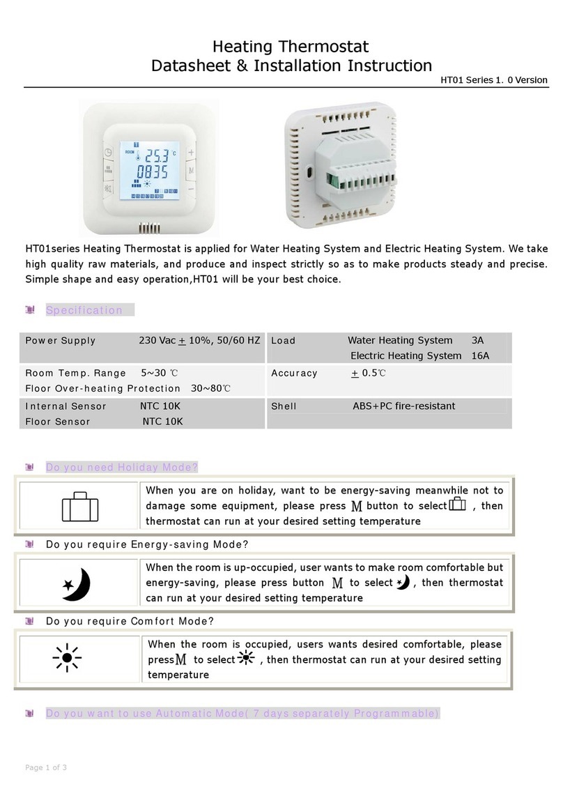
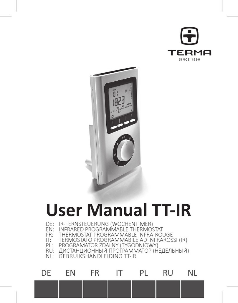
Hiwell HT01-16RF Manual

HIWELL HT01-16RF-V2/110203-4
HT01-16RF Electronic Heating Thermostat Installation & Operating Instructions
The controller is designed in accordance with current product standard EN 60730-2-9, and hereby fufills the requirements to both LVD and
EMC directives.
The controller must not be put into operation until it has been ascertained that the entire installation complies with current legislation applying to
electrical installations.
The warranty is only valid if the controller has been put into operation in accordance with the operating and installation instructions supplied with this
controller.
The HT01-16RF is an electronic on/off thermostat for control of temperature by means of an NTC sensor either placed externally or internally in the
thermostat.
Mounting of the floor sensor
Controller Installation
IMPORTAT: ALWAYS DISCONNECT THE MAINS SUPPLY VIA THE SWITCH IN THE MAIN FUSE BOARD, CONSUMER UNIT BEFORE COMMENCING ANY
ELECTRICAL WORK. WHEN CONNECTING CABLES TO THE THERMOSTAT, ENSURE THAT ALL TERMINAL SCREWS ARE FULLY TIGHTENED AND THAT EARTH
WIRES ARE SLEEVED AND THAT NO BARE WIRES ARE SHOWING.
The floor sensor should be installed within an approved non conductive
installation pipe in accordance with EN 61386-1, which is embedded in the
floor. The pipe (flexible conduit) should be placed as high as possible in the
subfloor. The floor sensor should be located equidistant between two runs of
the heating element with the tip at least 300mm away from the outside edge
of the heater.
The enclosed 3 meter sensor cable can be extended up to 50m by means of a
separate cable. If the extension cable is lighter than H05VV-F, it shall equally
be installed in an unbroken installation pipe. The installation pipe must not
contain any other cables, such as the supplies to the heating wire. The
switching peaks of such current supply lines may create interfering signals
that prevent optimum thermostat function. The heating supply cable should
be placed in a separate pipe.
In the event of sensor failure, replacement of the sensor can be carried out
with ease providing the sensor is installed within flexible conduit.
The floor sensor should never cross the heating element.
Placement of Thermostat
The thermostat is to be mounted on the wall with free air
circulation around it. Furthermore it has to be placed where it is
not influenced by any other heating sources (e.g. the sun), draft
from doors or windows, or by the temperature of an exterior wall.
The thermostat must be installed outside of rooms containing a
bath or shower. (Protective housing –IP20)
Electrical Connection
Electrical connections are to be made as detailed on
diagram.
The circuit supplying this controller must be protected by a
30mA RCD.
All electrical connections must be performed by a fully
qualified and part P certified electrician.
Any doubts surrounding the installation of this controller
should be passed to the distributer prior to installation.
Testing of all under-floor heating systems should take place
prior to floor coverings being installed.
1 Live from mains
2 Neutral from mains
3 Neutral to heaters
4 Live to heaters
5 Earth from heaters & mains
6 White wire from sensor
7 Black wire from sensor
Remove this sensor from
circuit before performing any
high voltage insulation tests.
Max Load
3600W / 16A
230V AC

HIWELL HT01-16RF-V2/110203-4
Sensor Resistance Values
Temperature℃
Resistance
Ohms
Temperature℃
Resistance
Ohms
5
22070.600
25
10000.000
10
17960.000
30
8312.400
15
14696.200
35
6943.400
20
12091.100
40
5827.250
Mounting & Installation
1. Release the front of the thermostat by
inserting a small flat screwdriver into
the 2 slots on the base.
2. Make electrical connections as
detailed in previous section.
3. Mount base part of thermostat onto
either a BS recessed or surface
mounted box.
Operating Instructions
Sensor Selection
The HT01-16RF is factory preset to use the room and floor temperature sensors. The following options are available. To change, press Mfor 3 seconds
then Monce more. Option can then be selected by the +/ - buttons.
rS
Room sensor ONLY
Heating will be switched on by the thermostat when the room temperature falls below the programmed
temperature. There is NO LIMIT on the temperature the floor can reach.
FS
Floor sensor
Heating will be switched on by the thermostat when the floor temperature falls below the programmed
temperature.*
rFS
Room and floor sensor
Heating will be switched on by the thermostat when the room temperature falls below the programmed
temperature. The thermostat will cut power to the heating if the floor reaches a temperature higher than the
programmed level. This is factory set at 65˚C This can re-programmed by the user at a level between 30˚C & 80˚C.
RECOMMENDED MAX: 40˚C
*If this thermostat is to be used with any under floor heating system designed for floor coverings other than ceramic, porcelain or stone floor tiles, the
‘floor sensor only’ option should be selected.
The (Comfort) (Energy save) and (Holiday) modes all need to be checked to ensure that the operating temperatures do not exceed the values
given by your heating / floor covering supplier. These temperature levels can be amended by holding for 3 seconds. The first value that can be
changed is the holiday mode. Press once more (quickly) to amend the energy save value, and once more for the comfort value.
Sensor failure
In the event of a possible sensor failure, the sensor can be checked according
to the table of resistance values below.
Technical Data
Voltage: AC230V ± 10% 50/60HZ
Power Consumption: 5W
Setting Range: 5 ~ 30ºC
Floor overheating 30 ~ 80˚C (factory set @ 65˚C)
Protection:
Protective housing: IP20
Housing Material: ABS + PC fire-resistant
Certification: CE
Floor Sensor: Rubber-Thermoplastic NTC 10K Sensor
Internal Sensor: NTC 10K

HIWELL HT01-16RF-V2/110203-4
Thermostat Programming
Your new thermostat has the following 3 modes. To manually select a specific mode press M.
Comfort mode
Select this mode to turn the under floor heating on. The heating will operate at the preset temperature. To alter the
preset temperature hold for 3 seconds then press again twice. Factory preset temperature : 25˚C
Energy-saving
Mode
Select this mode to turn the under floor heating down to a lower preset temperature. This temperature can be set
low enough to mean the heating is effectively turned off. To alter the preset temperature hold for 3 seconds
then press once again. Factory preset temperature : 15˚C
Holiday Mode
Select this mode to set the heating to a very low level whilst the room in unoccupied for a long period of time. This
mode should be selected to avoid frost damage whilst on holiday. To alter the preset temperature hold for 3
seconds. Factory preset temperature : 5˚C
Whilst the thermostat is operating in any of the modes above, the temperature can be manually altered by pressing the + or –buttons. The set
temperature will then revert back to the pre-set level at the next change of mode.
Date & Time Settings
To set the correct date & time press and hold for 3 seconds. Minutes will flash, press + / –to alter. Press once again to alter hours (24 hour clock).
Press once again to change week day. The numbers from 1 to 7 at the top of the screen represent Monday to Sunday.
7 Day Automatic mode
To select the 7 day timer mode press M until is displayed on the LCD screen. The thermostat will then switch between comfort & energy saving
mode (On/Off) automatically according to the day & time settings. Each day of the week can be programmed with individual settings.
To set up the automatic mode, press & hold for 3 seconds. To select the day of the week to be programmed press .
The bottom of the screen will show the following pattern of 24 numbered squares. Each square represents a 1 hour period of a 24 hour cycle. Each of
these 1 hour periods can be programmed to comfort or energy-save (On/Off) mode.
To make changes to the timed program, press + / –to select the 60 minute period. Then press to select the mode.
Pressing + or –will copy the selected mode from the previous 60 minute period.
Whilst programming, inactivity of 5 seconds will save the settings entered & the thermostat will return to normal operational mode.
Advanced Settings
To enter advanced settings press and hold Mfor 3 seconds. Press Monce again for each numbered function.
1. Temperature Calibration. If an accurate temperature read out from the room or floor differs from the read out on the thermostat, providing the
sensor has been checked against the stated resistance values, the thermostat can be calibrated using this function. The range is -8˚C ~ +8˚C
2. Sensor Selection. See beginning of the Operating Instructions section for details.
3. When operating the thermostat with the rFS sensor selection, the room temperature will display on the thermostat. This function allows the
user to see the current floor temperature.
4. When operating the thermostat with the rFS sensor selection, this function allows the user to amend the maximum temperature the floor can
reach. If the floor temperature exceeds this over-heating protection set-point, ALARM will flash on the screen and the heating output will cut
out.
Safety Information
WARNING: RISK OF ELECTRIC SHOCK. Disconnect power supply before making electrical connections. Contact with components carrying hazardous
voltage can cause electrical shock and may result in severe personal injury or death.
This thermostat is not a safety device and should only be used with safety certificated floor heating systems suitable for their specific purpose. In order to
avoid damaging your flooring, ensure the correct sensor selection & operating temperatures are selected during the programming process.
Thermostat Load and Contact Life:
We strongly recommend that you do not load the thermostat to the full extent of its 16A relay contact rating. It is good practice to restrict the load to
2kW~2.4kW (10A~12A). The relay is rated according to the requirements of EN 61810-1:2004 and EN60730-1 which are not representative of 'real life'
applications but an arbitrary test method. Critically, relay contact life is affected by loading. At 10A~12A the contact life is more than double its life at 16A.
In addition, measurement accuracy and control of room temperature is optimal at loads below 2kW~2.4kW. The relay contacts have resistance
proportional to current passed and greater currents cause greater losses across the relay contacts. These losses can increase the internal temperature of
the thermostat and affect the internal sensor used for air temperature control.

HIWELL HT01-16RF-V2/110203-4
Warranty
Hiwell warrants this product, to be free from defects in the workmanship or materials, under normal use and service, for a period
of one (1) year from the date of purchase by the consumer. If at any time during the warranty period the product is determined to be
defective, Hiwell shall repair or replace it, at Hiwell’s option.
If the product is defective, please return it, with a bill of sale or other dated proof of purchase, to the place from which you purchased it. Hiwell
will determine whether the product should be returned, or replaced.
This warranty does not cover removal or reinstallation costs, and shall not apply if it is shown by Hiwell that the defect or malfunction
was caused by damage which occurred while the product was in the possession of a consumer.
Hiwell’s sole responsibility shall be to repair or replace the product within the terms stated above.
HIWELL SHALL NOT BE LIABLE FOR ANY LOSS OR DAMAGE OF ANY KIND, INCLUDING ANY INCIDENTAL OR CONSEQUENTIAL
DAMAGES RESULTING, DIRECTLY OR INDIRECTLY, FROM ANY BREACH OF ANY WARRANTY, EXPRESS OR IMPLIED, OR
ANY OTHER FAILURE OF THIS PRODUCT. THIS WARRANTY IS THE ONLY EXPRESS WARRANTY HIWELL MAKES ON THIS
PRODUCT. THE DURATION OF ANY IMPLIED WARRANTIES, INCLUDING THE WARRANTIES OF MERCHANTABILITY AND FITNESS
FOR A PARTICULAR PURPOSE, IS HEREBY LIMITED TO THE ONE-YEAR DURATION OF THIS WARRANTY.
This Warranty does not affect your statutory rights.
CUSTOMER CARE
For any questions regarding product installation or operation, please contact the retailer you purchased this product from.
Recycling of obsolete appliances
Appliances with this label must not be disposed of with general waste. They must be collected separately and disposed of according to local
regulations.
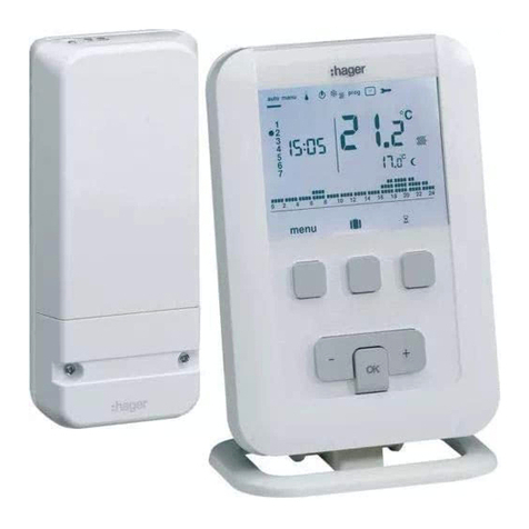
Other Hiwell Thermostat manuals
